Note: Descriptions are shown in the official language in which they were submitted.
~- W O 93/08892 2 12 ~ 3 3 ~ PCT/GB92/02035
~::
' .
~,-
:~ -
,: ~
MPROVEMENrS IN OR RELATING TO SEPAR~I0RS"
Thi~ ~nventiDn relates to separators and, more
.~ particularly, to separators for separating particulate solids
and semQ-solids contaminates from a ba~e liquid.
¶tor~ for separating particulate solids and
semi-sol~ contaeinates from a ba~e liquid are well known ~n
. ~ the art and in one form comprises a generally cyliNdrical
` vëssel, arr~dged with its axis substantially vertical,i a
conical hottom closing the lower region of the vessel and a
top or roof clos mg the upper region~ of the veqsel. The
vessel includes an outlet for "heavy" G~nsamin~te~, that i5 to
ay contaminates hav~ng a specific gravity greater than the
: specific yLavity of the base liquid, in the lower regions of
slid bottom and from which the heavy conta~inate~ are
'X ~ '~ 1 3 ~
W O 93/08892 PCT/G~92/02035
- 2 -
continuously extracted, an outlet for "light" contaminates,
that is to say contaminates having a specific gravity less thar,
the specific gravity of the base liquid, in the upper regions
of the ve~sel ar.,d from which light contaminates are
continuously extracted and an outlet for de-contam,inated liquid
in the upper regions of the vessel from which de-contaminated
liquid is continuolsly extracted.
The contaminated liquid is supplied into the vessel
tangentially through a side opening and the tangential entry of
~he contaminated base liquid generates circulatir,g flows withir,
the vessel, which induce laminar flows to assist in the
vertical displacement of the contaminates within the vessel.
This form of sepa,rator, hereinafter referrec', to as a
separator of the type defined" is well known in the art and
the construction and method of operation are kncwn in such
detail, as for e ~ le from British Patent Publication
No.2205512 and British Patent Publication No. 2158741, that no
further description of the separator, or its mode of operation,
is required herein.
Separators of the type defined work efficiently only
within relatively close l;~'ts, wherein the rates of flow of
contamonated ba~e liquid into the ves~el and through the
outlets fr~m the vessel are su~ætantially constant and the
residence time of the contaminates in the separator is
sufficient for said contaminates to fall or rise towards their
respective outlets and thereby out of the flcws to the de-
contaminated liquid outlet.
A serious problem with separators of the type t
defined arises when the contaminated h~ce liquid is very
,: i . .
heavily contaminated with light or heavy contaminates, when the
relevant contaminate outlet(s~ may be inadequate for dealing
with the excesQive volume of contaminates to be removed and
become choked with contaminates~ If, because of a complete or
partial blockage, the rate of flow through a contam~nates
outlet ~hould be reduced, the flow system throughout the
separator will ch~nge and con O ates wi11 be carried up the
- ;~0 ~3/08892 2 1213~v? PCT/GB92/0203
- 3 ~
.
spiralling flows in the upper central regions of the vessel and
will be carried over with the de-contaminated liquid. ~.
This problem is particularly acute when the
contamlnate contents of the contaminated ~ase liquid is
variable.
It has been proposed that this problem may be
ovexc~e by arranglng two separators of the type defined in
series, whereby the partially de-contaminated li~uid from the
first separator is supplied to the second separator, but this
solutlon simply means that the first separator is subjected to
the overload conditions defined above and, even if the first
separator is able to cope with the contaminates, the varying
volum~ of contaminates removed in the first separator can vary
the rate of flow of the partially de-contaminated liquid
flowing to the second separator and will thereby adversely
affect the efficiency of that separator~
It is well known in the art to add treatment
materials to a contaminated base liquid, to chemically cnange
one or more of said contaminates or to cause flocculation of
contaminates, to facilitate remove of the treated cont~mLnates
but, to be effective, such treatment materials must be
intimately mixed throughout the bace liquid and the flows -`.
within a separatQr of the type defined are too slow tO effect
the required distribution of a treatment material injected into
the vessel.
A further problem is that the treatment materials
often require a time period in order to effectively react with
the contaminates and, as in 8eparators of the type defined the ~-
greater part of the contaminates are removed, or are ccmmitted r~
to removal, In the early part of the entry of the contaminated
liquid into the separator, the residence time of the base
liquid in a separator of the type defined is inadequate for
most treatment materials to be effective on the contaminates
and for the separator to effectively separate the treated t
contaminates from the base liquid. r
The present invention seeks to provide a m~thod for
J ~'J J i~
~ J t~ JJ~
-- 4
separating contaminates from a base liquid and which is more
efficacious than the known methods of separating.
According to the present invention this is provided
a method for separating contaminates from a ba~e liquid
compri~ing the steps of supplying contaminated base liquid at a
~ubstantially uniform rate to a pre-treatment vessel in a
manner to cause circulating flows within said vessel, treating
said contaminated base liquid with a chemical treatment
material, allowing the treated contaminated base liquid to flow
from the ve~sel through an outlet so spaced from the inlet for
the contaminated liquid, in the direction of said circulating
fl~ws~ that the chemically treated contamanated base liquid
flowing through said outlet has spent at least a predetermined
time in said ve3~el and passing the treated contaminated base
liquid to a sep rator of the type defined.
Preferably the method includes the steps of
introducing the contaminated base liquid tangentially into the
said pre-treatment vessel.
In one embodiment the method is characterised by
the ~tep~ of inducing fl~w~ in said vessel to concentrate at
least part of the contaminates in one part of the vessel,
continuously extracting the concentration of contaminates from
said vessel, allowing chemically treated partially de-
contaminated base liquid to flow from the vessel through an
outlet spaced from that part of the ve~sel în which
contaminate~ are concentrated and pa~sing the chemically
- treated partially de-contaminated base liquid to the separator
of the type defined.
-In one embodiment the method is characterised by
the steps of arranging an outlet through ~hich heavy
contaminates can be extracted in the lower regions of the
ve~sel and arranging the outlet for the chemically treated
partially de-contaminated base liquid in the upper regions of
said vessel.
.. _ . _ .. .. ..
;i; 212~ 3rt P~ B~ 2 / ~20~
O~ r.~ R 1
-- 5
In another embodlment the method is characterised
by the steps of arranging an outlet through which light
cont~ninates can be extracted in the upper re~i~ons of the
vessel and arranging the outlet for the chemically treated
partially de-contaminated base liquid in the lower regions of
said vessel.
Prcferably the method is characterised by the step
of arranging an outlet through which light contaminates can be
extracted in the upper regions of the vessel, arranging an
outlet through which heavy contaminates can be extracted in the
lower regions of the vessel and arranging the outlet for the
chemically treated partially de-contaminated base liquid to
open into the mid-height region of the vessel.
In such an embodiment the method preferably
includes the steps of arranging the outlet for the chemically
treated partially de-contaminated base liquid to open adjacent
the central axis of the said vessel.
Preferably the method i9 characterised by the steps
of introducing the chemical treatment material into the
contaminated base liquid whilst said liquid is in said vessel.
Preferably the method is characterised by the steps
of introducing the treatment material into the contaminated
ba~e liquid ~efore ~aid contaminated base liquid is passed into
said vessel.
In one embodiment the method is characterised by
the step~ of selecting said chemical treatment material from
the group comprising ferric salts, (sulphate or chloride),
aluminium sulphates, lime, lime carbonate, cau~tic s~da or any
~ other of the material~ for chemically changing or flocculating
conta~inates.
In a preferred embodiment the method is
charscterised by the 9tep8 of introducing a sec~nd chemical
treatment material into the partially de-contaminated base
liquid being ~upplied to the separator of the type defined.
~ . . . . ... . . . . .. .~
-~- 212 l 3 ~ PCl/6B ~ ~ / 0 2 0 ~
1~ J~NUARY 1994 !`-
-- 6 -- :
Preferably the method i9 characterlsed by the 3teps
of selecting the second treatment material to comprise a
polymer material intended to cause a reac~ion o~ the
contaminates in the contaminated base liquid, after intimate
mixing with the first treatment material.
The invention also envisages apparatus comprising a
separator of the type defined in combination with a pre-
treatment vessel, characteri~ed by means for supplying
contaminated base liquid to said pre-treatment ves~l, mean~
for adding a chemical treatmen~ material to the contaminated
base liquid, means for generating circulating flows in the
chemically treated contami~ated base liquid in ~aid pre-
treatment vessel and mean~ for ~upplying chemically treated
contaminated base liquid from ~ald pre-treatment ve~sel to the
3eparator of the type defined.
Preferably the apparatu~ i9 characteri~ed in that
the pre-treatment ves~el comprise~ a ~ubstantially cylindrical
vessel arranged with it~ axis ~ubstantially vertical.
In one embodiment the appara~us i~ characterised
by means for removing heavy contaminate~ from the l~wer region~ -
of the ve~el and means for extracting chemically treated
I~ - partially de-contaminated base liquid from the upper regions of
¦ the vessel.
¦ ~ In another embodim~nt the app æ atus includes meæn~
¦ for extracting light cont~minates from an upper region of the
ve3sel and means for extracting chemically treated partially
de-contamlnated liquid from the lower region3 of the ve~el.
Preferably the apparatus i9 characteri~ed by mean~
for extracting light contaminates fron the upper regions of the
vessel, means for removing heavy contaminates from the lower
regions of the ve~el and means for removing chemically treated
contaminated ba~e liquid from a mid-height region of the pre- t
treatment ve~el.
, :
=3 SU~STI~UTE SI~EEr
.. . . ~
... . . ... . .. . .. , . ~ .. . . . .. , ` ` . ~ . -
P~TJ~ 2 / 0 20 3
. ~ . 2 :1.2 .~. !r ~ 2 ~L~ B~R l gg3 j
- 6a -
Preferably the apparatus includes means for
introducing the chemical treatment material into the
contaminated base liquid being supplied to said pre-treatment
vessel.
In one embodiment the apparatus is characterised by
means for mixing the said chemical treatment material into said
contaminated ~'ase liquid.
Preferably the apparatus is characterised by means
for mixing a second treatment material into the chemically
treated base liquid being supplied from said pre-treatment
vessel to said separator.
In one embodimen~ the apparatus is characterised
in that said means for mixing comprise a hydro-brake mixing
device.
The invention will now be described further by way
of example with reference to the accompanying drawings :in which
the single figure ~hows, diagramatically and partially in
cros.C-section~ a separator arrangement in accordance with the
I
, ~
... ,. ",.
~:~Z~ 33.~ ~-
~^^~O 93/08892 PCT/GB92/0203
- 7 -
invention.
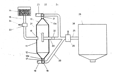
In the illustrated embodLment a pre-treatment vesQel ¦-
11, of ~enerally cylindrical form, is arran~ed with its
central axis substantially vertically, the lower regions of the j~
vessel are defined by a conical bott~m 12 and the upper regions .-
of the vessel are defined by a conical top 13. A central
aperture 12a in the bottom 12 defines an outlet for heavy
contamina~es and a central outlet 13a, in the top 13, defines
an outlet for light contaminates.
me vessel 11 is supplied with contaminated base
liquid fr~m a header tank 14 which discharges via a duct 15.
The duct 15 opens into the mid-height region of the ve~sel 11
and, via a tangential flow device 16, the liquid from duct 15
is dis~harged tangentially into the ve~sel 11 to genera~e
circulating flow therein.
Tangential devices 16 are well kncwn in the art and
are described in detail in, for ex2mple, the 8ritish Patent
Publications referred to hereinbefore and, accordingly, no
further description thereof is necessary.
With the tangential device 16 generating
circulating flows about the central axis of the vessel 11, and
which circl~lating flows esYentially develop laminar flows in --
the liquid, heavy contaminates in the liquid are allowed to
fall under gravity to the bottom 12 and lignt contaminates flow
upwardly within the vessel to the top 13.
The aperture 12a in the bott~m 12 of the vessel 11
opens to a flow pa~ age 17, which connects with a valve 18.
The valve 18, when in one position, ducts liquid from the flow
psssage 17 to a~duct 19, which leads to an exhaust. In its
other position the valve 18 duc~s liquid from the flow passage
17 to a duct 20.
In like manner the aperture 13a in the top 13 is
. . ;
open to a flow passage 21 which extends to a valve 22. The
v~lve æ, in one position, ducts the liquid from flow pa~age
. 21 to a duct 23, extending tO an exhaust, and in another
position a valve 22 dNcts liquid from flow p~age 21 to a
2~2133~ ~
W O 93/08892 PCT/GB92/0203
- 8 - 1
duct 24. ~ ¦
The ducts 20 and 24 extend to, and open into, a
comm~n duct 25, which constitutes the inlet duct to a separator~ '
of the type defined Z6. I;
In one mode for operating the apparatus described
thus far, and when a contaminat~d base liquid to be proce~sed
include a large volum2 of heavy contaminates, the valve 18 is
set to duct all the flow~ fr~m flow paq~age 17 through to duct
19. At the ~ame time the valve 22 i~ so positicned that flows
fr~m f low pa~cage 21 to duct 23 are clo5ed and all ~he flows
from flow pa3sage 21 are directed throu~h the valve 22 to duct
24~
With the valves 18 and 22 so ~et, and with the
vessel 11 charged with ccntaminated liquid, and heavi.ly
contaminated liquid entering the ves~el 11 via the duct 15 and
tangen~ial device 16, the yLeater Fart of the heavy
contaminates entering the ve~el 11 fall rapidly down the
ve3sel 11 to the conical bott 12, down the slopLng wall of
conical bottom 12 into the flow pa~sage 17 and to exhaust, via
the duct 19. The partially de-ccntammated liquld, perhaps
with some small part of the heavy contaminates as may be
carried upwardly in the ve~sel 11 and wi~h the light
cont~minates, flows through the fl~w pa3~age 21 to the duct 24
and, therefrom, via duct 2S mto the separator 26.
Thus, by this mcde of operatLng the pre-treatment
ve~sel 11, the greater part of the heavy contaminates are
removed from the contaminated liquid before said liquid is
passed into the conveneional separator 26.
In another mode of operation, when the contaminated
liquid include~ a large volume of light contaminates, the valve
22 is po~itioned to duct liquid from the flow passage ~1 to
the exhaust duct 23, and the valve 18 i9 set to open the flow
passage 17 to the duct 20.
Thus, in this mLde of operation, the light
contaminates entering the vessel 11 are allcwed to flow
upwardly within the vessel 11 and therefrom through ~he
21 ~ 3 ~ ~
.`~0 93/08892 PCT/GB92/0203
.. g
aperture 13 to flow pas~age 21 and through the valve 22 to the
exhaust duct 23. At the same time par~i lly de-contaminated
liquid, with the heavy contaminates and perhap~ some part ~of
the light con~inates, flows through aperture 12a, thr~ugh
flow passage 17, through the valve 18, and along the duct 20 .
to the duct 25.
In another m~de of operation, intended for use when
the contaminated liquid contains large volumes of both heavy
and light contaminates, the vessel is modified to include a
duct 30, which extends from the duct 25, through the wall of
the vessel 11 and terminates in a vertical duct 31, open at
both ends and having its axis concentric w~th the axis of the
vessel 11. the upper open end of the duct 31 lies above the
horizontal plane passing ~hrough tangential device 16 and the
lower open end of the duct 31 lies below said piane. The duct
30 conveniently includes a valve 32.
In operating the apparatus in this m~de, the valve
18 is positioned to discharge all the heavy contaminates
falling through the apert ~e 12a to the exhaust 19, tne valve
22 is positioned to discharge all the light contaminates rising
through the aperture 13a to exhaust 23 and the partially de-
contamlnated liquid is taken off through the duct 31, the duct
30, and through the valve 32 to the duct 25 supp~ying the
separator 26.
It will be appreciated that when the liquid has a
large vol~me of light or heavy contaminates the flow rates
through the relevant cont~;nates flow pa~sage 17 or 21 will
be controlled so that the maxi~um volume of contaminates with
the minimum volume of liquid is p~s~ed to exhaust
It will be observed that in all the above described i
embod~ments the contamlnated liqu1d is supplied to the vessel
under a substantially constant hydraulic head and with the
cross sectional area of the duct 15 greater than the sum of the
cross-sectional areas of all the outlets 12a, 13a ,nd 31, a
substantially uniform supply of partially ccntamm ated liquid
21 2133 '
W O 93/0~892 PCT/GB92~0203~ ~ - 3
-- 10 -- ~ ~
to the separator is obtained.
The separator apparatus a~ illustrated also includes
a mixing device 33, for example a hydro-brake device, in the- ~
supply conduit lS and by way of which a treatment material may
be added to the contaminated liquid via a duct 34. Thus, the
treatm~nt material can be continuously added to the
contaminated liquid and intimately mixed therewith in the
device 33. me mixing and distribution of the treatment
material through the contaminated liquid will c~ntinue as the
liq~id pas9es into and through the ve~sel 11 and the residence
time of the treated liquid in the ve~sel 11 will allow the
treatment material to be effective on the liquid and/or the
contaminates in the liquid, before the treated liquid is pa~sed
to the ~eparator 26.
Treatment materials which may advantageously be used
as flocculation/collection agents ca.nveniently comprises
ferric saltsj (sulphate or chloride), aluminium sulphates,
lime, lime carbonate, caustic soda, or any other of the
materials for chemically changing or flocculating contamlnates
well known in the art.
e apparatus preferably also includes a further
hydro-brake 35, in the duct 20, and via which a second
treatment msterial such as a "fixing" material, i.e. a polymer,
may be added to the partially contaminated liquid via a duct
36.
It will now be apparent that the apparatus
illustrated allcws a pre-treatment material tQ be added to the
contaminated liquid, intimately mixed throughout said material,
and,afforded a time interval within which to react with the
liquid or contaminates in the liquid before the treated liquid
is pa9sed to the separator 26 of the type defined, and the
apparatus also allows a 9econd treatment material to be
int ~ ed into the pre-treatment material to be introdused
into, and intimately mixed with, the pre-treated liquid before
said liguid is passed to the separator 26.
It will also be apparent that the treatment material
~0 93/08892 2 ~ 2 1 3 ~3~' PCT/G~92/0~03
aspects of the invention can be practised with or wîthout use
of the ve~sel 11 as a means for r~moving exce~sive heavy or
light contaminates from the contanunated liquid. ~ !
Whilst in the embodiment described above a slngle .-
mLlti-purpose, pre-treatment ve~sel has been described it will
be appreciated that the apparatus may include more than one
pre-treatment vessel and thus, for certain applications, the
apparatus may comprise a first pre-treAtment vessel for
rem~ving excess heavy contaminates from the liquid, a second
pre-treatment veqsel for removing excess light contaminates
from the partially decontaminated li~uid, and a third pre-
treatm~nt vessel for chemically treating the liquid before said
liquid is passed to the separator 26.
.
; . ~:t
~. ,; i ,,