Note: Descriptions are shown in the official language in which they were submitted.
4 6 b
SPECIFICATION
PROCESS AND APPARATUS FOR FORMING FRP FORMED PRODUCT
WITH SPIRAL GROOVE
FIELD OF THE INVENTION
The present invention relates to a process and
an apparatus for forming a fiber reinforced plastic
(FRP) formed product in a configuration of bar-shape,
tube-shape or so forth, on the outer periphery of which
a spiral groove is formed.
BACKGROUND ART
As is well known in the art, FRP formed products
have a ~Ycellent physical and chemical properties, such as
a high tensile resistance, high bending elastic modules,
15 and have excellent corrosion resistance and have been
employed as various corrosion resistive constructional
members. The process of fabrication of such FRP formed
products, comprises asteps, inwhich aresin isimpregnated
in a glass fiber base material, the glass fiber base
material is introduced into a mold for thermal setting
within the mold, and the cured formed product is withdrawn
therefrom. ~
2121466
For example, Japanese Unexamined Patent
Publication No. 55-5.5828 discloses a method for forming
uneven pattern on the surface of a fiber reinforced resin
body in the steps of arranging a thermosetting resin
impregnated glass fibers in mutually parallel relationship
on the surface of a mandrel, passing the glass fiber
reinforced resin body through a heating die to cause semi-
curing, winding a metal wire in spiral fashion, further
heating the metal wire wound body for curing, and removing
the metal wire after curing.
Also, Japanese Unexamined Patent Publication No.
3-~Q~-539 disclosesa method for forming spiral projection on
the fiber reinforced rod by win~ing reinforcing string or
tape of synthetic resin or so forth in spiral fashion on the
fixing end of a FRP rod contA;ning the carbon fiber to form
the uneven pattern on the peripheral surface. In Figure 1
of the publication, there is illustrated the embodiment, in
which the string like members are wound on the surface of
2121466
-- 2 --
the rod in intersecting fashion to form intersecting spiral
projections.
Japanese Unexamined Patent Publication No. 3-
129040 discloses the construction, in which a resin
impregnated fiber is wound on the surface of semi-cured bar
shaped bodyinintersectingfashion tobe cured togetherfor
forming the intersecting spiral projection on the surface
of the bar-shaped body.
In case of the forming process as disclosed in
Japanese Unexamined Publication No. 55-55828, a hard steel
wire of 6 mm diameter is employed to be wound on the
peripheral surface of the semi-cured resin for forming the
uneven pattern. Then, the hard steel wire wound resin body
is re-heated for completing curing. Thereafter, the hard
steel wire is removed from the cured body.
Here, since circular cross section metal wire is
employed for forming the uneven pattern by burying the part
of the metal wire in the surface portion of the resin body
with projecting the rem~n~ng part. Re-curing by re-
heating is performed at this condition. However, theproblems are inherently encountered in this technology.
First of all, since the part of the metal wire is
projecting from the surface of the resin body, the surface
of the resin body is placed away from the surface of the
heating furnace to degrade heat transmission efficiency.
Low heat transmission efficiency should cause not only the
low curing performance but also low uniformity of finishing
of the surface of the formed body, Furthermore, in order to
prevent the metal wire to be completely buried within the
resin, the semi-curing step is inherent.
21 2 1 4~6
-- 3 --
In case of the Japanese Unexamined Patent
Publications Nos. 3~ ~3 and 3-129040, both take the
construction in which the separate resin impregnated fiber
is bonded on the FRP rod. Therefore, the projection can be
easily peeled off the surface of the FRP rod. Especially,
in case of the intersecting spiral construction, tendency
of peeling off becomes greater since the bonded fiber
inherently projects outwardly at the intersection.
Also, Japanese Examined Patent Publication No.
57-18484, U. S. Patent No. 4,770,832 and further in view of U.
S. Patent No. 1,6~0,4C1 and U. S. Patent No. 5,047,104 show
relevant technologies. Japanese Examined Patent
Publication No. 57-18484 discloses a process forming a
notched or yLoo~ed surface fiber reinforced product.
Japanese Examined Patent Publication No. 57-18484 requires
rotationofthe tubularmember forwinding and unwi nti ing the
metallic line on and from the outer periphery thereof.
U. S. Patents Nos. 4,620,401 and 5,047,104 disclose
the bobbin rotating about the cylindrical core, it winds
embossment or unimpregnated strands to be integrated with
the cylindrical core similarly to the above-mentioned
Japanese Unexamined Patent Publications Nos. 3-~Q~9 and
3-129040. Since embossment or unimpregnated strands are
integrated with the core after win~ing, U. S. Patents Nos.
4,6~0,4Q1 and 5~047,104 do not require unw;n~iing or releasing
them from the outer periphery of the core. Also, these two
prior art does not form the grooves but forms helical
projections on the outer periphery of the core to encounter
the problems as pointed out with respect to the above-
mentioned Japanese Unexamined Patent Publications Nos. 3-
2121466
-- 4 --
~n~g and 3-129040. --
DISCLOSURE OF THE INVl~NTION
In view of the problems set forth above, it is an
object of the present invention to provide a FRP formed
product which permits higher efficiency in heat
transmission upon heating curing, complete curing at only
one curing process, and can provide smooth finished surface
of the formed product with Pnh~nc~ bon~ing ability to a
concrete.
According to one aspect of the invention, a
process for forming a FRP formedproductcomprises thesteps
of:
lS feeding reinforcing fibers and impregnating a
thermosetting resin to said fibers for forming a non-cured
resin impregnated fiber body;
winding strip bodies on said non-cured resin
impregnated fiber body in intersecting spiral fashion;
pressing said strip bodies into said non-cured
resin impregnated fiber body;
heating said non-cured resin impregnated fiber
body in a molding station for curing the resin to form a
cured body; and
removing said strip from said cured body.
According to another aspect of the invention, a
continuous drawing apparatus for a formed body with
intersecting spiral grooves comprises:
a resin impregnating portion for impregnating a
thermosetting resin to a bunch of fibers to form a non-cured
- 2 1 2 1 4 66
-- 5 --
resin impregnated fiber body:
a strip w;nd; ng device portion for winding strips
on the surface of said non-cured resin impregnated fiber
body in intersecting spiral fashion, which strip w;n~; ng
device portion including
a first rotary bodyrotating about said non-
cured resin impregnated fiber body in one
direction;
a second rotary body rotating about said
non-cured resin impregnated fiber body in the
other direction opposite to said one direction;
bobbins rotatable supported on and carried
by respective of said first and second rotary
bodies; and
amotor for driving respective of said first
and second rotary bodies;
a molding and curing station for heating the
resin impregnated in said fibers for curing to form a cured
body;
a strip unwinding device portion for unw; n~; ~g
and removing said strip from said cured body, said strip
unwin~;ng device portion including
a first rotary body rotating about said
cured resin impregnated fiber body in one
direction;
a second rotary body rotating about said
cured resin impregnated fiber body in the other
direction opposite to said one direction;
bobbins rotatable supported on and carried
by respective of said first and second rotary
-- 6 --
~1~14~6
bodies; and
amotorfordrivingrespectiveofsaid first
and second rotary bodies;
a drawing out portion for drawing the cured body
from said molding station; and
acontrol portionco~ne~.tedto said strip winding
device portion and said strlp unwin~in~ device portion for
controlling operations thereof.
According to a further aspect of the invention,
a process for forming a fiber reinforced plastic formed
product with spiral grooves, in a continuous pultrusion
process of the fiber reinforced plastic formed product, the
process for forming intersecting spiral y.ooves on the
fiberreinforcedplastic formedproduct comprisesthe steps5 of:
win~ing a plurality of strip bodies on an outer
circumference of the fiber reinforced plastic formed
product before curing in intersecting manner;
depressing a portion of the strip bodies wound
around said fiber reinforced plastic formed product toward
a center of the fiber reinforced plastic formed product for
forming said intersecting spiral glooves on the outer
circumference of said fiber reinforced plastic formed
product,
curing the fiber reinforced plastic product
with said strip bodies wound thereon and depressed
thereonto;
removing said strip bodies from the fiber
reinforced plastic formed product after curing: and
means for controlling speed of respective
relative angular displacement between said strip bodies
and said fiber reinforced formed plastic product
relative to a feeding speed of said fiber reinforced
plastic formed
2 1 2 1 ~66
-- 7 --
product for adjusting winding pitches of said strip bodies.
According toastill further aspect apparatus for
forming a fiber reinforced plastic formed product with
spiral grooves, comprises, in the forming apparatus of the
fiber reinforced plastic formed product:
winding device portion for win~;ng strip bodies
on anouter peripheryofthe fiber reinforcedplastic formed
product before curing in intersecting manner;
molding station for depressing the strip bodies
wound on the fiber reinforced plastic formed product toward
acenterofsaid fiberreinforced plasticformed product and
heating said fiber reinforced plastic formed product for
curing;
unwin~ing device portion for removing said strip
bodies from said fiber reinforced plastic formed product
after curing; and
control portion for controlling said winding
device portion and said unw;n~ing device portion, said
control portion controlling speed of respective relative
angular displacement between said strip bodies and said
fiber reinforced plastic formed body for adjusting winding
pitches of said strip bodies.
Each of said winding device portion and said
unw;n~;ng device portion may comprise a stationary frame
member, a pair of rotary bodies rotatably supported on said
frame member and driven for rotating about said fiber
reinforced plastic formed product in mutually opposite
directions, bobbins mounted on respective rotary body and
a motor for rotatingly driving said rotary body.
According to a yet further aspect of the
. . .
~ ~ 1 2 1 466
-- 8 --
invention, a process for forming a fiber reinforced plastic
formed product with spiral grooves formed on the outer
periphery thereof, comprises the steps of: ~
fee~ing a composite material prepared by
impregnating a synthetic resin in a reinforcement fiber
across a curing station;
placing a first elongated strip supply means
upstream of said curing station and causing relative
angular displacement between first elongated strip supply
means and said composite material passing thereacross in a
first w;nAing direction for winAing a first elongated strip
on an outer periphery of said composite material in a first
spiral direction;
placing a second elongated strip supply means
upstream of said curing station and causing relative
angular displacement between second elongated strip supply
means and said composite material passing thereacross in a
second winding direction opposite to said first win~ing
direction forwinding asecond elongated strip on saidouter
periphery of said composite material in a second spiral
direction in intersecting with said first elongated strip;
impressingsaidfirstandsecondelongatedstrips
into the peripheral portion of said composite material in
said curing station;
placing a first elongated strip take-up means
downstream of said curing station and causing relative
angular displacement between said first elongated strip
take-up means and a cured product fed out from said curing
station in a first unwin~ing direction for unwinding said
first elongated strip from said cured product with leaving
2121466
a first spiral yLoove on the cured peripheral surface of
said cured product; and
placing a second elongated strip take-up means
downstream of said curing station and causing relative
angular displacement between said secon~ elongated strip
take-up means and said cured product in a second unw;~ing
direction for unwinding said second elongated strip from
said cured product with leaving a second spiral groove
intersecting with said first spiral yloove on the cured
peripheral surface of said cured product; and
controlling speed ofrespective relative angular
displacement between said first elongated strip supply
means and said composite material and between said ~econ~
elongated strip supply means and said composite material
relative to a feeding speed of said composite material for
adjusting w; nAi ng pitches of said first and second
elongated strips.
Each of said first and -secon~ elongated strip
supply means may include two elongated strip supply sources
for winding the elongated strips with a phase shift
corresponding to a half of a spiral pitch. Also, each of
said first and second elongated strip take-up means may
include two take-up members for unwinding the elongated
strips wound with phase shift respectively.
According to a still further aspect, a process
for forming a fiber reinforced plastic formed product with
spiral yLooves formed on the outer periphery thereof,
comprises the steps of:
fee~;ng a composite material prepared by
impregnating a synthetic resin in a reinforcement fiber
6 6
-- 10 --
across a curing station;
placing a first elongated strip supply means
upstream of said curing station and causing relative
angular displacement between first elongated strip supply
means and said composite material pAssing thereacross in a
first winding direction for w;nAing a first elongated strip
on an outer periphery of said composite material in a first
spiral direction;
placing a second elongated strip supply means
upstream of said curing station and causing relative
angular displacement between second elongated strip supply
means and said composite material passing thereacross in a
second winAing direction opposite to said first wi ~A ing
direction forwinding asecond elongated stripon said outer
periphery of said composite material in a second spiral
direction in intersecting with said first elongated strip;
impressingsaidfirstandsecondelongatedstrips
into the peripheral portion of said composite material in
said curing station;
placing a first elongated strip take-up means
downstream of said curing station and causing relative
angular displacement between said first elongated strip
take-up means and a cured product fed out from said curing
station in a first unwinding direction for unwinAin~ said
first elongated strip from said cured product with leaving
a first spiral groove on the cured peripheral surface of
said cured product;
placing a second elongated strip take-up means
downstream of said curing station and causing relative
angular displ~ Q nt between said second elongated strip
2 1 2 1 4 66
take-up means and said cured product in a e~con~ unwin~i~g
direction for unwinA;ng said second elongated strip from
said cured product with leaving a second spiral groove
intersecting with said first spiral yloove on the cured
peripheral surface of said cured product; and
controllingsaidfirstandsecondelongatedstrip
supply meansand said first and-seconA elongatedstrip take-
up means to rotate in synchronism with a feeAi~g speed of
said composite material for adjusting spiral pitches of
respective of first and second elongated strips wound in
intersecting manner.
According to a still further aspect, a process
for forming a fiber reinforced plastic formed product with
spiral grooves formed on the outer periphery thereof,
comprises the steps of:
feeAing a composite material prepared by
impregnating a synthetic resin in a reinforcement fiber
across a curing station;
placing a first elongated strip supply means
upstream of said curing station and causing relative
angular displacement between first elongated strip supply
means and said composite material passing thereacross in a
first w;nA;ng direction for winding a first elongated strip
on an outer periphery of said composite material in a first
spiral direction;
placing a second elongated strip supply means
upstream of said curing station and causing relative
angular displacement between second elongated strip supply
means and said composite material passing thereacross in a
second winding direction opposite to said first winAing
- 21~1466
- 12 -
direction forwinding asecond elongatedstrip on said outer
periphery of said composite material in a second spiral
direction in intersecting with said first elongated strip;
impressingsaidfirstandsecondelongatedstrips
into the peripheral portion of said composite material in
said curing station;
placing a first elongated strip take-up means
downstream of said curing station and causing relative
angular displacement between said first elongated strip
take-up means and a cured product fed out from said curing
station in a first unwin~ing direction for unwin~ing said
first elongated strip from said cured product with leaving
a first spiral yLoove on the cured peripheral surface of
said cured product;
placing a second elongated strip take-up means
downstream of said curing station and causing relative
angular displacement between said second elongated strip
take-up means and said cured product in a second unwin~ing
direction for unwin~ing said second elongated strip from
said cured product with leaving a second spiral y~oove
intersecting with said first spiral y~oove on the cured
peripheral surface of said cured product;
providing a drive means for producing a
rotational driving force;
transmitting said rotational driving force to
said first and second elongated strip supply means and said
first and second elongated strip take-up means for rotation
in mutually opposite directions; and
controlling said drive means for adjusting the
rotation speeds of said first and second elongated strip
2121466
~. ,
- 13 -
supply meansand said first andsecond elongated striptake-
up means depen~ing upon the fee~ing speed of said composite
material for providing a predetermined phase shift between
said first and second elongated strips.
According to a yet further aspect of the
invention, an apparatus for forming a fiber reinforced
plastic formed product with spiral yLooves, comprises,
feedingmeansforfe~i ng acylindricalcomposite
material prepared by impregnating a synthetic resin in a
reinforcement fiber across a curing station;
a first elongated strip supply means provided at
upstream of said curing station and causing relative
angular displacement with respect to said composite
material passing thereacross in a first win~ing direction
for winding a first elongated strip on said composite
material in a first spiral direction;
asecond elongatedstrip supply means provided at
upstream of said curing station and causing relative
angular displacement relative to said composite material
passing thereacross in a second win~ing direction opposite
to said first wi n~i ng direction for winding a second
elongated strip on said outer periphery of said composite
material in a second spiral direction in intersecting with
said first elongated strip;
impressing means provided in said curing station
for impressing said first and second elongated strips into
the peripheral portion of said composite material in said
curing station;
a first elongated striptake-up means provided at
downstream of said curing station and causing relative
2121466
- 14 -
angular displacement relative to a cured product fed out
from said curing station in a first unw;nAing direction for
unwi nA i ng said first elongated strip from said cured
product with leaving a first spiral groove on the cured
peripheral surface of said cured product;
asecondelongatedstriptake-upmeansdownstream
of said curing station and causing relative angular
displacement relative to said cured product in a second
unwi nAi ng direction for unw; nA; ng said second elongated
strip from said cured product with leaving a second spiral
groove intersecting with said first spiral groove on the
cured peripheral surface of said cured product; and
means for controlling speed of respective
relative angular displacement between said first elongated
strip supply means and said composite material and between
said second elongated strip supply means and said composite
material relative to a feeA; ng speed of said composite
material for adjusting winding pitches of said first and
second elongated strips with providing a predetermined
phase shift between said first and second elongated strips.
The apparatus may further comprise means for
controlling speed of respective relative angular
displacement between said first elongated strip supply
means and said composite material and between said second
elongated strip supply means and said composite material
relative to a f~A;ng speed of said composite material for
adjusting winding pitches of said first and second
elongated strips. Each of said first and second elongated
strip supply means may include two elongated strip supply
sources for winding the elongated strips with a phase shift
2121466
- 15 -
corresponAing to a half of a spiral pitch. Also, each of
said first and second elongated strip take-up means may
include two take-up members for unwin~ing the elongated
strips wound with phase shift respectively.
According to a yet further aspect of the
invention, an apparatus for forming a fiber reinforced
plastic formed product with spiral y ooves, comprises,
feedingmeansforfee~ingacylindricalcomposite
material prepared by impregnating a synthetic resin in a
reinforcement fiber across a curing station;
a first elongated strip supply means provided at
upstream of said curing station and causing relative
angular displacement with respect to said composite
material passing thereacross in a first winding direction
for winding a first elongated strip on said composite
material in a first spiral direction;
asecond elongatedstrip supply means provided at
upstream of said curing station and causing relative
angular displacement relative to said composite material
passing thereacross in a second winding direction opposite
to said first wi n~i ng direction for winding a second
elongated strip on said outer periphery of said composite
material in a second spiral direction in intersecting with
said first elongated strip;
impressing means provided in said curing station
for impressing said first and second elongated strips into
the peripheral portion of said composite material in said
curing station;
a first elongated striptake-up means provided at
downstream of said curing station and causing relative
2121466
angular displacement relative to a cured product fed out
from said curing station in a first unwin~;ng direction for
unwinding said first elongated strip from said cured
product with leaving a first spiral y~oove on the cured
peripheral surface of said cured product;
asecondelongatedstriptake-upmeansdownstream
of said curing station and causing relative angular
displacement relative to said cured product in a c~Con~
unwin~i~g direction for unw;n~;ng said ceconA elongated
strip from said cured product with leaving a second spiral
yLOOVe intersecting with said first spiral groove on the
cured peripheral surface of said cured product; and
controlling means for controlling said first and
second elongated strip supply means and said first and
second elongated strip take-up means to rotate in
synchronism with a feeding speed of said composite material
for providing a predetermined phase shift between said
first and second elongated strips
According to a yet further aspect of the
invention, an apparatus for forming a fiber reinforced
plastic formed product with spiral grooves, comprises,
feedingmeansforfP~;ngacylindricalcomposite
material prepared by impregnating a synthetic resin in a
reinforcement fiber across a curing station;
a first elongated strip supply means provided at
upstream of said curing station and causing relative
angular displacement with respect to said composite
material passing thereacross in a first win~;ng direction
for winding a first elongated strip on said co~rosite
material in a first spiral direction;
2 1 2 1 466
a second elongated strip supply means provided at
upstream of said curing station and causing relative
angular displacement relative to said composite material
passing thereacross in a second win~ing direction opposite
to said first winding direction for win~i~g a Q~con~
elongated strip on said outer periphery of said composite
material in a second spiral direction in intersecting with
said first elongated strip;
impressing means provided in said curing station
for impressing said first and second elongated strips into
the peripheral portion of said composite material in said
curing station;
a first elongated striptake-up means provided at
downstream of said curing station and causing relative
angular displacement relative to a cured product fed out
from said curing station in a first unwin~ing direction for
unwinding said first elongated strip from said cured
product with leaving a first spiral groove on the cured
peripheral surface of said cured product;
asecondelongatedstriptake-upmeansdownstream
of said curing station and causing relative angular
displ~s- ~t relative to said cured product in a second
unwinding direction for unwinding said second elongated
strip from said cured product with leaving a second spiral
yloove intersecting with said first spiral groove on the
cured peripheral surface of said cured product;
a drive means for producing a rotational driving
force;
transmitting means for transmitting said
rotational driving force to said first and second elongated
~121466
-- 18 --
strip supply means and said first and second elongated strip
take-up means for rotation in mutually opposite directions;
and
controlling means for controlling said drive
5 means for adjusting the rotation speeds of said first and
second elongated strip supply means and said first and
second elongated strip take-up means depen~i ng upon the
feeding speed of said composite material for providing a
predetermined phase shift between said first and second
10 elongated strips.
The above-mentioned and other objects, aspects
and advantages will become clear to those skilled in the art
by the preferred and practical embodiment consistent with
21214~6
-- 19
the principle of the invention, which will be discussed and
illustrated in connection with the accompanying drawings.
BRIEF DESCRIPTION OF THE DRAWINGS
Fig. 1 is an explanatory illustration of an
apparatus for forming a FRP formed product with a spiral
groove, according to the present invention;
Fig. 2 is an explanatory illustration showing a
groove forming station in Fig. 1; and
Fig. 3 is an explanatory illustration showing an
adhesion test between a FRP formed product formed by the
apparatus of the invention and a concrete.
BEST MODE FOR IMPLEMENTING THE INVENTION
Thepresentinventionwillbediscussed in detail
hereinafter with reference to the accompanying drawings.
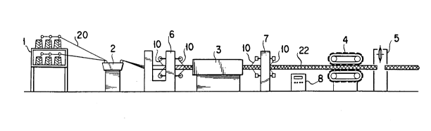
As shown in Fig. 1, the present invention is
constructed in a pultrusion process of the FRP formed
product, constituted of the steps for withdrawing a glass
fiber base material 20 from a fiber supply station 1,
impregnating a resin to the withdrawn glass fiber base
material 20 by a resinimpregnating device station 2, curing
by heating at a mold station, after curing, withdrawing the
formed product by a withdrawing device 4, and cutting into a
desired dimension by a cutting device station 5, strip bodies 10
are wound around the outer periphery of the FRP formed
product before curing, i.e. the glass fiber base matrix in
2121466
- 20 -
an intersecting fashion and impressed toward the center of
the FRP formed body, and is ~e."~ved from the FRP formed
product after cutting so that the intersecting spiral
groove is formed in the FRP formed product.
Here, one embodiment of a groove forming station
30 for the FRP formed product will be concretely discussed
with reference to Fig. 2.
Thegrooveformingstation30generallycomprises
a w;n~;ng device portion 6provided in the former process to
the molding station 3 for winding the strip body 10 on the
FRP formed product before curing, i.e. the glass fiber base
matrix, a unwinding device portion 7 provided in the latter
process of the molding station 3 to unwind the strip body 10
from the FRP formed product 22, and a control portion 8 for
controlling the winding device portion and the unw;n~;ng
portion.
The winding device portion 6 includes a frame
member 11, a rotary bodies 12 rotatably supported on the
frame member 11 and rotatable about the glass fiber base
matrix 20, bobbins13 rotatably mountedon the rotary bodies
12, and a motor 14 for rotatingly driving the rotary bodies
12. The rotary bodies 12 are provided at front and back
sides of the frame member 11. Two rotary bodies 12 at both
sides are provided mutually opposite rotating directions.
In each of rotary bodies 12, two bobbins 13 are rotatably
2121466
- 21 -
mounted at a symmetric positions with respect to a rotary
shaft. Although a single motor 14 is employed, it is
designed to drive two rotary bodies12 in mutually opposite
directions through gear train. It should be noted that the
strip bodies 10 are wound on the bobbin 13.
The unw;n~;ng device portion 7 includes a frame
member 11, a rotary bodies 12 rotatably supported on the
frame member 11 and rotatable about the FRP formed product
22, bobbins 13 secured on the rotary bodies 12, and a motor
14 for rotatingly driving the rotary bodies 12. Similarly
to the w; n~; ng device portion 6, two rotary bodies 12 are
provided at front and back sides of the frame member 11.
Two rotary bodies 12 at both sides are provided mutually
opposite rotating directions. In each of rotary bodies12,
two bobbins 13 are secured at a symmetric positions with
respect to a rotary shaft. Although a single motor 14 is
employed, it is designed to drive two rotary bodies 12 in
mutually opposite directions through gear train. It should
be noted that the strip bodies10 are wound on the bobbin13.
Furthermore, in the vicinity of the winding
device portion 6 and the unwinding device portion 7, the
control portion 8 is provided. The control portion 8 is
connected to the winding device portion 6 and the unw~n~;~g
device portion 7 so that a control for adjusting a pitch of
spiral grooves can be performed by varying rotation speeds
_ - 22 - 21 21 466
in relation of a fPP~i~g speed of the FRP formed product 22.
With the construction set forth above, the glass
fiber base matrix, in which the resin is impregnated, is
wound therearound with the strip body 10 wound on the
bobbins13 on one of the rotary bodies12 rotating about the
glass fiber base matrix at the front side of the winding
device portion 6 and is wound therearound the strip body
wound on the bobbins13 on the other rotary body12 rotating
in the opposite direction to the former so that the strip
bodies 10 are wound on the surface of the glass fiber base
matrix 20. As the strip body10, a rope form synthetic resin
is employed. Any desired cross sectional configuration of
the groove can be attained by varying the cross sectional
configurationofthe strip body10. Subsequently, the glass
fiber base matrix 20 is fed into the molding station 3, in
which the strip bodies 10 are depressed into the surface of
the glass fiber base matrix 20 and the glass fiber base
matrix is heated for curing to be formed into the FRP formed
product with the spiral grooves. Furthermore, in the
unwinding device portion 7 as later process of the molding
station 3, the bobbins 13 on one of the rotary bodies 12 at
the front side of the unw;n~;ng device portion 7 are rotated
to unwind the strip bodies 10 from the FRP formed product
22. Also, the bobbins 13 on the other rotary body 12 at the
back side of the unwinding device portion 7 are rotated to
2121466
- 23 -
unwind the remaining strip bodies 10 from the FRP formed
product 22. Therefore, the FRP formed product with the
intersecting spiral grooves can be formed.
Next, results of adhesion test of the FRP formed
product with the spiral grooves of the present invention
when the FRP formed product and so forth are employed as
reinforcements for the concrete construction will be
discussed. Employing the FRP formed product with the
intersecting spiral groove, a FRP formed product with a
single spiral groove, a FRP formed product without groove,
and an iron reinforcement, a fast-setting cement 15 is
secured on respective one ends, as shown in Fig. 3. After
curing, with abutting the fast-setting cement 15 onto an
abutting plate 16, the other end is pulled to measure the
adhering force. The results are shown in the following
table l.
TABLE 1
Form Adhering Force (Kgf/cm)
Intersecting Groove 65
Single Groove 35
Without Groove 27
- 21 21 465
- 24 -
Iron Reinforcement 68
Pulling speed: 5 mm/min
As shown in the table 1, it has been confirmed
that the FRP formed product with the intersecting grooves
holds substantially the same adhering force to the iron
reinforcement.
As can be appreciated herefrom, the present
invention is particularly applicable for a drawing process
so that forming and heating curing can be performed
substantially at the same timing so that the following
advantages can be att~;ne~.
Since the heat can be directly transferred from
the periphery of the molding station so that the resin can
be cured uniformly and efficiently. Therefore, the surface
of the formed product can be smooth.
Also, since the strip (substantially flat cross
section) is used to be wound around the non-cured FRP formed
produce, the strip can be drawn into the molding station in
the state wound around the FRP formed product. Then,
the strip is pressed into the FRP formed produce by the
inner periphery of the molding station. However, the strip
cannot be buried completely within the FRP formed product.
Therefore, the strip can be removed after curing of the FRP
2121466
- 25 -
formed product without causing peeling off of the extra
cured resin.
The area and depth of the groove to be formed can
be varied arbitrary.
Furthermore, by providing the spiral groove in
intersecting fashion, the area of the groove can be
increased without narrowing the pitch of winding the strip
so that bonding ability to the concrete can be increased.
INDUSTRIAL APPLICABILITY
As set forth above, the process and apparatus for
forming the FRP formed product with the spiral grooves can
achieve practically important advantages that can produce
with lesser process steps, the FRP formed product with the
spiral grooves which has a sufficiently high tensile
strength, holdsequivalent adhering force withthe concrete
to the conventional iron reinforcement when it is applied
as a reinforcement for the concrete construction, and has
excellent corrosion resistance.