Note: Descriptions are shown in the official language in which they were submitted.
,~9~~~'r~'>
~9.~~~6~
DATA BROADCASTING SYSTEM
BACKGROUND OF THE INVENTION
1. Field of the Invention
The present invention relates to a data
broadcasting system suitable for electronically
distributing, via an artificial satellite, such
information mainly composed of texts (or characters) as
newspapers, magazines, and books that are conventionally
distributed directly to readers or sold at stores on a
daily or otherwise regular basis.
2. Description of the Related Art
Conventionally, newspapers, magazines, and
books are distributed in hardcopy in most cases.
However, recent advancement in data communications
' technologies is making it possible to distribute
,..,
information hitherto conveyed in printed matters such as
'~ mentioned above through electronic means. For example,
on--line network services are widely available in which a
:,.: ..
. .a
database containing information such as obtained from
newspapers and the like can be accessed by personal
computers via a public telephone network for information
retrieval.
,,.
1 _
......,.. .,.. ,1, .:
f ~- : ,
~~.21~6~
In addition, there already exists a service
for distributing desired newspaper or magazine articles
to contracted subscribers by means of facsimile.
However, the distribution of information in
hardcopy presents following problems for example:
(1) As long as one reads only one copy of
newspaper or magazine on a regular basis, there may be
little problem in handling the copy; however, as the
number of copies increases, they become too bulky to
handle them with convenience;
(2) Tf a family or an office subscribes only
one copy of newspaper for example, only one family or
office member can read the copy at a time;
(3) Consumption of a huge volume of paper
caused by hardcopy distribution is presenting an
environment preserving program in terms of
deforestation;
(4) Transportation and delivery of hardcopy
require a lot of manpower, thereby increasing
transportation cost; and
(5) Transportation and delivery of hardcopy
require a lot of vehicles driven by internal combustion
engines, thereby presenting an air-pollution problem.
-a-
~~.~1~~~
Conventionally, however, the information
delivery by electronic means is too costly for the
general public to use it conveniently because o.f a
relatively high fee for using the database service plus
a telephone charge for accessing it.
OBJECTS AND SUMMARY OF THE INVENTION
It is an object of the present invention to
provide a data broadcasting method for delivering
information at a lower cost than that of the
conventional counterpart.
According to one aspect of the present
invention there is provided a data broadcasting method
for transmitting predetermined data via a broadcasting
channel, comprising the steps ofs
inserting coded data such as a newspaper, a
magazine, and a book into a predetermined artificial
satellite channel;
transmitting the coded data via an artificial
satellite;
receiving the transmitted data from the
artificial satellite; and
decoding the received data to reproduce the
2~2~5~5
According to another aspect of the present
invention there is provided a data broadcasting system
for transmitting predetermined data via a broadcasting
channel, comprising:
multiplexing means for multiplexing data such
as a newspaper, a magazine, and a book with a broadcast
signal to generate a multiplexed signal;
transmitting means for transmitting the
' multiplexed signal to a predetermined artificial
satellite channel;
receiving means fox receiving. the multiplexed
signal via the predetermined artificial satellite
channel;
separating means for separating the data from
the multiplexed signal received by the receiving means;
and
decoding means for decoding the separated data
by the separating means.
According to further aspect of the present
invention there is provided a data broadcasting
apparatus for transmitting predetermined data via a
broadcasting channel, comprising:
multiplexing means for multiplexing a video
signal, a audio signal, and data such as a newspaper, a
2~215~~
magazine, and a book to generate a multiplexed signal;
and
transmitting means for transmitting the
multiplexed signal to a predetermined artificial
satellite channel.
According to still further aspect of the
present invention there is provided a broadcast
receiving apparatus for receiving a broadcast signal
transmitted via a broadcasting channel, comprising:
receiving means for receiving the broadcast
signal transmitted via an artificial satellite channel;
separating means for separating data such as a
newspaper, a magazines and a book from the received
broadcast signal; and
decoding means for decoding the separated
data.
Specifically, in a data broadcasting method,
data such as newspapers, magazines, and books are
inserted in a predetermined channel of an artificial
satellite, the inserted data are transmitted via the
satellite, the transmitted data are received by a data
receiver provided in each subscribing household or
office for example, and the received data are recorded
~~2~.56
onto a recording medium such as a hard disk or a compact
magneto-optical disc.
Far the above-mentioned channel, a channel for
digital data transmission of a broadcasting satellite or
a communications satellite can be used. The above-
mentioned data to be transmitted and received can
contain article data and retrieval data for retrieving
the article data. These retrieval data and article data
can be scrambled.
In the data transfer system~having the above-
mentioned constitution. newspaper and magazine data are
transmitted via an artificial satellite and received by
a data receiver to be recorded onto a recording medium,
thereby eliminating the need for delivery by human
workers and therefore reducing delivery cost. In
addition, the data receiving party need not access
the
data sending party, thereby reducing an operator load
on
:=z
,
::.;
the data receiving party side.
,:a
The above and other objects, features and
advantages of the present invention will become more
apparent from the accompanying drawings, in which like
reference numerals are used to identify the same or
similar parts in several views.
<t
;..;,
'i
~121~6~
BRIEF DESCRIPTION OF THE DRAWINGS
Fig. 1 is a diagram illustrating the data
broadcasting system practiced as one preferred
embodiment of the present invention;
Fig. 2 is a block diagram illustrating a
constitution of a broadcasting center of the embodiment
of Fig. l;
Fig. 3 is a diagram illustrating spectra of
data to be entered in an FM modulator of Fig. 2;
Fig. 4 is a diagram illustrating a format of
digital channel data in a digital channel signal
multiplexes of Fig. 2;
Fig. 5 is a diagram illustrating range bits of
the format of Fig. 4;
Fig. 6 is a diagram illustrating a format of a
packet of an independent data channel;
Fig. 7 is a diagram illustrating a function of
a header of Fig. 6;
Fig. 8 is a diagram illustrating oblique
multiplexing in independent data channel;
Fig. 9 is a diagram illustrating data recorded
on a packet of the independent data channel of Fig. 8;
Fig. 10 is a diagram illustrating positions of
,: ;
packets constituting the independent data channel;
2~2~,~~~
Fig. 11 is a diagram illustrating a detail
format of a packet;
Fig. 12 (a) and (b) are schematic diagrams
illustrating a retrieval page and an article page
respectively;
Fig. 13 is a diagram illustrating a
relationship between a retrieval page and an article
page;
Fig. 14 is a block diagram illustrating a data
receiver of Fig. 1 practiced as a preferred embodiment
of the invention; and
Fig. 15 is a block diagram illustrating detail
constitutions of a BS (Broadcasting Satellite) tuner and
decoder of Fig. 14.
DESCRTPTION OF THE PREFERRED EMBODIMENTS
..: r
:..i
This invention will be described in further
:..: t
detail by way of example with reference to the
accompanying drawings.
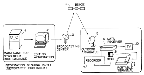
Now, referring to Fig. l, there is shown the
data broadcasting system practiced as one preferred
embodiment of the present invention. A newspaper
'."~;
publisher.as an information sending pasty has a
mainframe 1. The mainframe 1 holds a newspaper page
_ g _
~~~~~6
database. The newspaper page database contains article
information to be printed and layout information. The
data held in this database are transmitted to an editing
workstation 2 as required to be edited.
To be more specific, the article data are
edited by the editing workstation 2 on an article type
basis into a form in which the data can be most easily
retrieved by the receiving party. For example, this
editing facility creates a screen fox retrieval in which
a page is reduced with its layout unchanged arid only
headlines displayed. Further, the retrieval screen
(headlines) is related to the articles whose headlines
are displayed so that selecting one of the headline
displays the corresponding article. The data thus
edited into a form in which the receiving party can
retrieve the data easily are transmitted to a
broadcasting center 3 via a ground data circuit.
The broadcasting center 3 has a transmitting
apparatus as shown in Fig. 2 for example. That is, data
coming from the newspaper publisher are composed of
newspaper data, a scramble key, common information, a
receiver ID, and subscription terms for example. Of
these pieces of data, the newspaper data are fed to a
data scrambler 14 to be scrambled according to a pseudo
- 9 -
N
random series generated by a PN (Pseudo Noise) generator
13. The scrambled data are sent to an independent data
channel multiplexes 12. The pseudo random series
generated by the PN generator is set according to the
scramble key provided by the newspaper publisher.
Tn addition to the above-mentioned scramble
key, the common information, the receiver ID, and the
subscription terms axe supplied to an encrypting circuit
11 to be encrypted. The encrypted data are supplied to
the independent data channel multiplexes 12 as related
information.
The independent data channel multiplexes 12
multiplexes the scrambled newspaper data corning from the
data scrambler 14 with the related information coming
from the encrypting circuit 11 to send the result to a
digital channel signal multiplexes 15.
The above-mentioned constitution makes up an
encoder 25 for generating data in an independent data
channel to be described with reference to Fig. 4.
A audio signal (at least a part of which is a
2~.215~ 3
Fig. 3. The digital channel signal multiplexes 15
multiplexes the entered audio signal (digital audio
signal) with data coming from the encoder 25 to send the
result to a 4-phase DPSK (Differential Phase-Shift
Keying) modulator 16.
The 4-phase DPSK modulator 16 performs 4-phase
DPSK modulation on the entered data and outputs the
result to a video signal/digital channel signal
multiplexes 17. A video signal to be broadcast is by
the broadcasting center 3 is also entered in the video
signal/digital channel signal multiplexes 17. While the
audio signal entered in the digital channel signal
multiplexes 15 is digital, the video signal entered in
the video signal/digital channel signal multiplexes 17
is analog.
The video signal/digital channel signal
multiplexes 17 frequency-multiplexes the entered video
signal with the signal coming from the 4-phase DPSK
modulator 16 and sends the result to an FM modulator 18.
The FM modulator 18 FM-modulates a predetermined carrier
~? by the entered signal and sends the result to an up-
converter l9. The up-converter 19 frequency-converts a
frequency of the entered FM signal to a frequency on an
order of GHz. The resultant FM signal is power-
- 11 -
2~21~~~
amplified by a power amplifier 20 and the amplified
signal is sent to a transmitting antenna 21 to be
transmitted to an artificial satellite (broadcasting
satellite or communications satellite).
Referring to Fig. 3, there is shown frequency
spectra of the signal entered in the FM modulator 18.
As shown in the figure, the video signal has a frequency
band up to about 4.5 MHz. The signal coming from the 4-
:.5
phase DPSK modulator 16 is a signal with a frequency of
5.727272 MHz being a subcarrier. That is, the video
signal and the 4-phase DPSK signal are multiplexed for
transmission.
Referring to Fig. 4, there is shown a format
(in mode A) of the 4-phase DPSK modulated digital
channel data. As shown in the figure, one frame is made
up of data consisting of 64 horizontal bits times 32
vertical bits, amounting to a total of 2048 bits. A
range of first 2 bits times 32 bits is for recording a
frame sync signal, a control signal, and a range bit.
Since one frame of data is transmitted in one
ms, a transmission rate becomes 2.048 Mbps.
The frame sync signal provides synchronization
between frames. The control signal consists of 16 bits.
As listed in Table l, bit l indicates mode A or mode B.
- 12 -
y.. ,', 4; ~' .;., ~ . . : ;
~~2~~~~
The mode B will be described later. Bits 2 and 3
indicate whether the television audio signal (the signal
accompanying the video signal) is a stereo signal or a
monaural one-channel signal or a monaural two-channel
signal.
Bits 4 and 5 indicate whether a signal to be
added besides the television audio signal is a stereo
signal, a monaural one-channel signal or a monaural two-_
channel signal or a signal other than a audio signal.
Bits 6 through 15 are extension bits reserved for future
use. Bit 16 is a code for indicating that a sound
output is to be suppressed or not.
2~.~~.5~5
Table 1
CONTROL O O O ~ O
CODE ~ ...
BIT NO.
CONTENT MODE TV SOUND ADDITIONAL EXTENS SOUND
g OF SOUND ION OUTPUT
CONTROL A/B STEREO STEREO BITS SUP-
MONAURAL MONAURAL PRESST
ONLY 1 ONLY 1 ON
CHANNEL CHANNEL
TRAMS- TRAMS-MITTED
MTTTED MONORAL 2
MONORAL CHANNELS
2
CANNELS TRAMS-MITTED
TRAMS- SIGNALS
MTTTED OTHER THAN
SOUND TRANS-
MTTTED
NOTEc IF CONTROL CODE BIT 1 IS "1", BITS 4 AND 5 ARE
HANDLED AS EXTENSION BITS.
Table 2 lists details of bits 1 through 5 and
bit 16 listed in Table 1. That is. when bit 1 is "0",
it indicates mode A; when bit 1 is "1", it indicates
mode B. When bit z is °'0" and bit 3 is "0", it
indicates that the television audio signal is stereo;
when bit 2 is °'0°' and bit 3 is "1", it indicates that
the television audia signal is the monaural two-channel '
signal (to be recorded to sound l and sound 2 in the
format of Fig. 4); and when bit 2 is "1" and bit 3 is
_ 1~
"0", it indicates that the television audio signal is
the monaural one-channel signal (to be recorded to sound
1 in the format of Fig. 4). When bit 2 and bit 3 are
both "1", it specifies nothing in particular.
When bit 4 iS "0" and bit 5 iS "0°', it
indicates that the additional sound is stereo; when bit
4 is "0" arid bit 5 iS "1°', it iridicateS 'that the
additional sound is the monaural two-channel signal (to
be recorded to sound 3 and sound 4 in the frame of Fig.
4); and when bit 4 is "1" and bit 5 is "0°', it indicates
that the additional sound iS the monaural one-channel
signal (to be recorded to sound 3 of in the format of
Fig. 4). When bit 4 and bit 5 are both "1", it
indicates that a signal to be transmitted is a non-audio
signal.
Further, bit 16 is set to "1'° when the sound
output is suppressed; it is set to "p" when the
suppression is cleared.
- 15 -
~121~~~
Table 2
CONTROL
CODE CONTROL CODE BIT ASSIGNMENT
BIT
NO.
~1 MODE A:O; B:l
TV SOUND OPERATING MODE
p 1
0 STEREO MONAURAL
ONLY 1 *SOUND 1
CHANNEL* USED.
TRANSMITTED
1 MONAURAL 2 **SOUND 1.
CHANNELS** NOT AND
TRANSMITTED SPECIFTED 2 USED.
ADDTTIONAL SOUND OPERATING MODE (MODE
A)
0 1
0 STEREO MONAURAL
~ ONLY 1 *SOUND 3
USED.
~ CHANNEL
TRANSMTTTED
1 MONAURAL 2 SIGNALS **SOUND 3
CHANNELS** OTHER THAN AND
TRANSMITTED SOUND 4 USED.
TRANSMITTED
~ IF "1", SOUND OUTPUT IS SUPPRESSED; IF
'0",
SUPPRESSION IS CLEARED.
~Z2.~5~ i
Referring to Fig. 4, four ranges of 10 bits x
32 bits each that follow the first range of 2 bits x 32
bits are recorded with the data of sound 1 through sound
4 respectively. Each range of 10 bits x 32 bits is
arranged with 32 samples of sound data. That is, the
number of bits per sample is 10. However, an analog
audio signal is converted into a digital signal in which
one sample consists of 14 bits. Of these bits, upper 10
bits of significant digit are selected to be transmitted
as one sample of data. That .is, referring to Fig. 5,
since the upper 10 bits of significant digit of the 14-
bit data are selected, there are five selectable ranges.
The range bit in the first range of 2 bits x 32 bits
indicates one of these ranges of upper 10 bits.
zn mode A, each of these ranges of l0 bits x
32 bits is arranged with one channel of sound data. Tn
mode B, a range of 20 bits x 32 bits is arranged with
one channel of sound data. Thus, mode B transmits sound
data of higher quality than that transmitted in mode A.
The sound data 4 is followed by data of the
independent data channel in a range of 15 bits x 32
bits. The last range consisting of 7 bits x 32 bits of
the frame is arranged with a horizontal-direction error
correction code (C1).
- 17 _
~~.~:~6~
the data of the independent data channel shown
in Fig. 4 is transmitted on a packet basis. Referring
to Fig. 6, there is shown a format of the packet. In
the figure, one packet consists of 288 bits. First 16
bits provide a header. Following 190 bits form
substantial data. Last 82 bits form a packet error
correction code (Cl). Of the 16 header bits, first five
bits provide service identification codes and remaining
11 bits provide a horizontal--direction error correction
code (check bits) (C1) for the service identification
code. As will be described with reference to Fig. 11,
the service identification codes include information for
identifying the related information and the newspaper
data.
Since five bits axe provided fox service
identification, 32 services can be identified
theoretically. However, as shown in Fig. ?, a code in
which each of the five bits is "0" is used to indicate
that the packet is transmitted as a dummy packet.
Actually, therefore, remaining 31 codes are used to
identify 32 service types.
Referring to Fig. 8, nine frames of data, each
frame shown in Fig. 4, are collected to form a super
-- 18 -
2~.21~~~
frame. A bit string of one packet is foamed by data in
one super frame.
As shown in Fig 8, the data in the frames are
transmitted sequentially vertically. Consequently, a
burst error is caused in the vertical direction in Fig.
8. To make it hard for the burst error to occur, the
independent data channel in the range of 15 bits x 32
bits is multiplexed obliquely. As shown in Fig. 8,
since the independent data channel is 15 bits long
horizontally, there are 15 oblique directions. The
packet consisting of 2.88 bits shown in Fig. 6 is related
to each of these, directions. Therefore, the independent
data channel has packets of 15 positions (packets of 15
channels). Thus, the oblique multiplexing allows data
constituting each packet to be interleaved with data of
another packet, thereby enhancing resistivity to burst
error.
Referring to Fig. 9, there is shown a
schematic diagram illustrating packets in the
independent data channel. As shown in the figure, one
of the 15 packets is assigned with the related
information outputted from the encrypt9.ng circuit 11 of
Fig. 2. The remaining 14 packets Gan be assigned with
newspaper data (the newspaper data outputted from the
-- 19
data scrambler 14) of newspaper publishers A through I
for example. It should be noted that one newspaper
publisher can use a plurality of packets at a time. In
an embodiment of Fig. 9, one packet is used for
transmitting the related information and two packets are
used for transmitting newspaper data of each of
newspaper publishers A, B, and C.
Referring to Fig. 10, there is shown a
schematic diagram illustrating contents of the packets
of the 15 positions. In an embodiment of Fig. 10,
packet 1 is assigned with related information and
packets 2 through 15 are assigned with data of newspaper
publishers A through I respectively. That is, the
related information and the newspaper data A through I
' are transmitted to each subscriber at a time.
Referring to Fig. 11, there is shown a detail
format of a packet. As shown in the figure, the first
v 16 bits of the packet consisting of 288 bits provide a
header, in which data (the service identification data
'.of Fig. 6) for identifying the related data or newspaper
data is disposed.
The following 190 bits are used to contain the related
information or newspaper data. The last 82 bits provide
a error correction code.
- 20 -
212~.~~~
The related information is divided into common
information and individual information. The common
information starts with a type identification code for
identifying whether the information is common or
individual. lThe type identification code is followed by
a newspaper data identifier for identifying which of
newspaper A, B, C and so on the data comes from. This
identifier is followed by data indicating a position of
a packet to be used. That is, following the newspaper
data identifier, a code is disposed for indicating which
of packets of positions 1 through 15 the data belongs
to.
The packet position indicating code is
followed by a scramble key. The scramble key is
received by a data receiver 6 to be described. The
received scramble key allows the data scrambled by the
data scrambler of Fig. 2 to be descrambled.
The scramble key is followed by a broadcasting
start time followed by a broadcasting end time., The
broadcasting end time is followed by other necessary
codes.
On the other hand, the individual information
starts with a type identification code followed by a
receiver TD. The receiver ID is assigned to the data
- 21 -
~121~~~
receiver of Fig. 1 for example. The receiver ID is
followed by subscription terms of the receiver. Then,
another receiver ID and its subscription terms follow,
followed by still another receiver ID and its
subscription terms, and so on.
As shown in Fig. 10, since the related
information assigned to the first packet is always
transmitted, the receiving party can monitor the related
information for the scramble key of a predetermined
newspaper publisher and the broadcasting start and end
times. If a data receiver having a receiver ID
contained in individual information transmitted when the
common information is not transmitted matches the
subscription terms of the ID, the receiving party can
download newspaper data of a corresponding newspaper
publisher.
The newspaper data are divided into retrieval
page data and article page data. The retrieval page
data starts with a start code (the retrieval page a of
Fig. 11). The start node indicates that the newspaper
data of newspaper A for example starts here. The start
code is followed by a newspaper data identifier. The
newspaper data identifier identifies which of newspaper
publishers A, B, C, and ~o on the data belongs to. The
- 22 -
:;
newspaper data identifier is followed by a type
identification code for making distinction between a
retrieval page and an article page. The type
identification code is followed by page identification
data. The page identification data identifies a genre
of articles such as a political page, an economic page,
and a sports page for example.
. The page identification data is followed by a
,
, headline, a character size and font of the headline, and
:.;
. .S
positional data of the head line, in this order. The
positional data is followed by layout data for
indicating whether the headline is oriented vertically
.;
or horizontally. The layout data is followed by a
s
pointer for accessing a position in which an article
:
under the headline is described.
The above-mentioned retrieval page "a" has the
format of the first packet. In the second and
subsequent packets, a format of retrieval page "b" may
be used. That is, the format of the retrieval page "b"
..
..:
f has no start code arid newspaper data identifier.
On the other hand, the article page of the
newspaper data starts with the type identification data,
followed by a layout (the article page "a"). The layout
is followed by an outline and article data shown detail
....
i
- 23 -
contents of the article. Tf the outline or the article
data is too long to be contained in one packet, the
packet shown by the article page "b" is added to the
article page "a". The article data is terminated with
an end code.
Referring to Fig. 12, there is shown a
schematic diagram of a retrieval page and an article
page. As shown in Fig. 12 (a), the retrieval page shows
only headlines. On the other hand, as shown in Fig. 12
(b), the article page shows not only a headline but also
an article itself introduced by the headline and an
outline of the article. A subscriber selects a desired
headline by clicking it with a pointing device such as a
mouse to display the corresponding outline and article
as shown in Fig. 12 (b).
Referring to Fig. 13, there is shown an
overall layout packets of retrieval and article pages.
As shown in the figure, the article page packets are
preceded by the retrieval page packets. Each retrieval
page packet has a pointer to a corresponding article
page packet.
Referring to Fig. 1 again, the data arranged
as mentioned above are transmitted from the broadcasting
center to the satellite ~ to be delivered to each
..i
~'i . _ 2~
.,.;, ~:. ~ ., ~ '<
.
~1~156~
receiving party (subscriber). On the receiving party
side, the data signal received by an outdoor apparatus 5
is converted to a predetermined intermediate-frequency
(IF) signal. The IF signal is put in a data receiver 6.
The data received by the data receiver 6 are demodulated
there to be supplied to a recorder 7 to be recorded on a
recording medium such as a compact magneto-optical disc
8 for example. The subscriber loads this disc 8 on a
portal terminal 9 for example to retrieve the retrieve
page for a desired article page. Alternatively, the
subscriber reads the data recorded in the recorder 7 to
display the read data on a television receiver (TV) 10.
Referring to Fig. 14, there is shown a
preferred embodiment of the data receiver 6. As shown,
the IF signal entered via the outdoor apparatus 5 is
supplied to a BS tuner 32. The subscriber presets a
subscribed newspaper data broadcasting time on a timer
circuit 34. The timer circuit 34 incorporates a clock
and outputs a signal to a processor 35 composed of a
. ..
CPU, a ROM, and a RAM upon expiration of the preset
time.
Upon receiving the signal from th.e timer
circuit 34, the processor controls a power on/off
controller 36 to turn on a power circuit 37. The power
"y
v
25 -
~~~~5~~3
circuit 37, when turned on, supplies a power to each of
the above-mentioned components to make the data receiver
6 ready to operate.
At that time, the processor 35 controls the BS
tuner 32 via a BS tuner controller 31 to select a
channel through which data of a subscribed newspaper
publisher is transmitted. From the IF signal, the BS
tuner 32 decades a signal of the selected channel to
send the decoded signal to a decoder 33. The decoder 33
decodes data in a packet containing subscribed newspaper
data. The processor 35 supplies the data decoded by the
decoder 33 to a recording medium 42 via a recording
medium driver 41 in the recorder 7 to record the data
onto the recording medium. The recording medium 42 is
made up of a hard disk for example. Alternat:.vely, the
processor 35 controls such that the output.of the
decoder 33 is recorded onto a recording medium made up
of the compact magneto-optical disc 8 for example via.a
recording medium driver 43.
Upon receiving a predetermined instruction,
the processor 35 controls such that the data recorded on
the recording medium 42 or the compact magneto-optical
disc are reproduced to be supplied to a video circuit 38
in which the data are converted into a video signal.
- 26 -
The video signal coming from the video circuit 38 is
entered in the television receiver 10 to be displayed on
its screen. Alternatively, as described with reference
to Fig. 1, the compact magneto-optical disc recorded
with the newspaper data is loaded on the portable
terminal 9 to display the data on its screen.
In this case, since the newspaper data are
composed of retrieval and article pages as described
with reference to Fig. 12, the retrieval page (Fig. 12
(a)) can be displayed first to show headlines, according
to which the subscriber selects an article page (Fig. 12
(b)) to read. Therefore, even if the screen of the
gortable terminal 9 or the television receiver ZO is too
small to display a newspaper page in its entirety, it
. presents substantially no inconvenience in displaying
only a selected article.
'y When the preset broadcasting end time expires,
the timer circuit 3~ outputs a signal to the processor
.a
35: At this timer the processor 35 controls the power
circuit 37 via the power on/off controller 36 to stop
supplying the power, upon which the newspaper data
download operation completes.
If the subscriber is receiving another channel
during the time when subscribed newspaper data are
_':i
i
- 27 -
2~2~.~6a
broadcast, the processor 35 displays a message on the
television receiver 10 via the video circuit 38 to
prompt the subscriber for changing channels.
Alternatively, the processor 35 generates an alarm sound
for the same purpose. Further. it is possible for the
processor 35 to forcibly and automatica7.ly change
channels.
In the above-mentioned setup, the subscriber
sets the time at which the data receiver 6 starts
operating. A variation can be made to it that, with the
power on, broadcasting start and end times for
individual newspaper data included in the related
information are used to automatically preset a
broadcasting time of subscribed newspaper data, thereby
allowing the subscriber to automatically receive
subscribed newspaper data without the subscriber's
setting a time at which the data receiver 6 starts
operating>
Referring to Fig. 15. there are shown detail
constitutions of the BS tuner and the decoder 33 by way
of example. The IF signal captured via the outdoor
apparatus 5 is entered in an FM demodulator 71 of the BS
tuner 32. The FM demadulator 71 is supplied with a BS
tuner control signal from the BS tuner controller 31.
~121~~~
The FM demodulator 71 demodulates the IF signal of a
channel corresponding to the BS tuner control signal
into base band signal, which is outputted to a video
signalfdigital channel signal separator 72. The video
signal/digital channel signal separator ?2 separates a
video signal and a digital channel signal from the
entered signal to output the video signal to the
television receiver 10 for example to display the signal
on the screen thereof.
On the other hand, the digital channel signal
separated by the video signal/digital channel signal
separator 72 is entered in a 4-phase DPSK demodulator 73
to be demodulated. The demodulated signal is entered in
a digital channel signal separator 74 to be separated
into a audio signal and an independent data channel
signal. The audio signal is sent to the television
receiver 10 if the audio signal is one that corresponds
to the above-mentioned video signal.
The digital channel signal separator 74
' separates.the independent data channel signal from the
signal coming from the 4-phase DPSK demodulator 73 and
separator 81 separates the newspaper data and the
related information from the entered signal to send the
separated newspaper data to a data descrambler 87 and
the separated related information to a decoder 82. A
memory 83 stores a receiver ID assigned to the decoder
33 (the data receiver 6).
When subscription terms of a receiver ID
matching the receiver ID stored in the memory 83 comes
as related information, the decoder 82 sends the
subscription terms to a subscription terms comparator 84
to store the subscription terms in a built-in memory
84A. At the same time, the decoder 82 decodes the
scramble key transmitted as related information (common
information) to output the result to an on/off switch
85.
Then, upon decoding a data identifier from the
entered related information. the decoder 82 supplies the
decoded data identifier to the subscription terms
comparator 84. The subscription terms comparator
compares the entered data identifier with the
subscription terms stored in the memory 84A. The
subscription terms contain a data identifier of a
subscribed newspaper. Unless the subscription terms
contain a terms violation such as subscription fee in
- 30 -
arrears, the subscription terms comparator 84 outputs a
control signal for setting the on/off switch 85 to the
on side when the data identifier stored in the memory
84A matches the data identifier supplied from the
decoder 82. Thus, the scramble key coming from the
decoder 82 is supplied to a PN generator 86 via the
on/off switch 85.
..j
The PN generator 86 generates a pseudo random
' series according to the entered scramble key. Using the
pseudo random series coming from the PN generator 86,
the data descxamblex 87 descrambles the newspaper data
supplied from the newspaper data/xelated information
's
separator 81. The descrambled newspaper data axe
supplied to the recorder 7 to be recorded onto the
compact magneto-optical disc 8 or the recording medium
84 such as a hard disk.
It will be apparent that the present invention
is also applicable to the transmission of such character
data other than newspaper data as magazines and books.
Further, the present invention is applicable to the
transmission of image data and sound data at a time.
As described and according to the invention,
there is provided a data broadcasting system in which
data coming via a satellite is received by a data
- 81 -
~1~1~~~
receiver to be recorded on a recording medium, thus
making it unnecessary for a subscriber t0 aCCeSS the
data sending party, resulting in the simplified, low-
cost delivery of data such as newspapers, magazines, and
books.
While the preferred embodiments of the present
invention have been described using specific terrns, such
description is for illustrative purposes only, and it is
to be understood that changes and variations may be made
without departing from the spirit or scope of the
appended claims.