Language selection

Search

Patent 2121651 Summary

Third-party information liability

Some of the information on this Web page has been provided by external sources. The Government of Canada is not responsible for the accuracy, reliability or currency of the information supplied by external sources. Users wishing to rely upon this information should consult directly with the source of the information. Content provided by external sources is not subject to official languages, privacy and accessibility requirements.

Claims and Abstract availability

Any discrepancies in the text and image of the Claims and Abstract are due to differing posting times. Text of the Claims and Abstract are posted:

  • At the time the application is open to public inspection;
  • At the time of issue of the patent (grant).
(12) Patent: (11) CA 2121651
(54) English Title: TRACK AND RAIL-FORM SLIDER COMBINATION
(54) French Title: CHEMIN DE ROULEMENT ET PIECE COULISSANTE COMBINES
Status: Expired and beyond the Period of Reversal
Bibliographic Data
(51) International Patent Classification (IPC):
  • B66C 09/10 (2006.01)
  • A63G 21/00 (2006.01)
  • B61B 03/00 (2006.01)
(72) Inventors :
  • DOHERTY, DARRELL (Canada)
(73) Owners :
  • GOLDEN ROD WELDING LTD.
(71) Applicants :
  • GOLDEN ROD WELDING LTD. (Canada)
(74) Agent: NATHAN V. WOODRUFFWOODRUFF, NATHAN V.
(74) Associate agent:
(45) Issued: 1999-11-30
(22) Filed Date: 1994-04-19
(41) Open to Public Inspection: 1994-09-25
Examination requested: 1996-01-30
Availability of licence: N/A
Dedicated to the Public: N/A
(25) Language of filing: English

Patent Cooperation Treaty (PCT): No

(30) Application Priority Data: None

Abstracts

English Abstract

A track and rail-form slider combination is described which includes a rail-form slider having a top surface, a bottom surface, and sides extending between the top surface and the bottom surface. Pour corners are formed where the top surface meets the sides and the bottom surface meets the sides. A track is provided which includes a plurality of roller supports. At least four rollers are secured to each roller support. Each roller engages the rail-form slider solely at one of the corners.


French Abstract

Un chemin de roulement et une pièce coulissante combinés sont décrits qui comportent une pièce coulissante ayant une surface supérieure, une surface inférieure, et des côtés s'étendant entre la surface supérieure et la surface inférieure. Des angles de versement sont formés à l'emplacement où la surface supérieure touche les côtés et où la surface inférieure touche les côtés. Un chemin de roulement est prévu qui comporte une pluralité de supports de roulement. Au moins quatre roulements sont fixés à chaque support de roulement. Chaque roulement n'entre en contact avec la pièce coulissante que dans les angles.

Claims

Note: Claims are shown in the official language in which they were submitted.

6
THE EMBODIMENTS OF THE INVENTION IN WHICH AN EXCLUSIVE PROPERTY
OR PRIVILEGE IS CLAIMED ARE DEFINED AS FOLLOWS:
1. A track and rail-form slider combination, comprising:
a. a rail-form slider having a top surface, a bottom
surface, aides extending between the top surface and the bottom
surface and four corners formed where the top surface meets the
sides and the bottom surface meets the sides; and
b. a track, including:
i. a plurality of roller supports;
ii. at least four rollers secured to each roller
support, each roller engaging the rail-form slider solely at
one of the corners.
2. The track and rail-form slider combination as defined in
Claim 1, wherein the at least four rollers are arranged in
pairs, each pair being mounted on a roller assembly bar in a
generally "V" shaped configuration.
3. The track and rail-form slider combination as defined in
Claim 2, wherein each roller assembly bar has two pairs of
rollers, each pair of rollers being axially spaced along the
roller assembly bar.
4. The track and rail-form slider combination as defined in
Claim 2, wherein biasing means are disposed between one of the
roller assembly bars and the roller supports, the biasing means
biasing the roller assembly bar into engagement with the
rail-form slider such that the roller assembly bar moves in and out
to accommodate imperfections in the rail-form slider.
5. The track and rail-form slider combination as defined in
Claim 1, wherein each roller is disposed at an angle of between
30 degrees and 60 degrees relative to one of the top surface
and the bottom surface of the rail-form slider.

7
6. The track and rail-form slider combination as defined in
Claim 5, wherein each roller is disposed at an angle of 45
degrees relative to one of the top surface and the bottom
surface of the rail-form slider.

8
7. A track and rail-form slider combination, comprising:
a. a rail-form slider having a top surface, a bottom
surface, sides extending between the top surface and the bottom
surface and four corners formed where the top surface meets the
sides and the bottom surface meets the sides; and
b. a track, including:
i. a plurality of roller supports;
ii. at least four rollers secured to each roller
support, each roller engaging the rail-form slider solely at
one of the corners with each roller disposed at an angle of
between 30 degrees and 60 degrees relative to one of the top
surface and the bottom surface of the rail-form slider, the
rollers being arranged in pairs, each pair being mounted on a
roller assembly bar in a generally "V" shaped configuration;
and
iii. at least one biasing spring disposed between
one of the roller assembly bars and the roller supports, the
biasing spring biasing the roller assembly bar into engagement
with the rail-form slider such that the roller assembly bar
moves in and out to accommodate imperfections in the rail-form
slider.
8. The track and rail-force slider combination as defined in
Claim 7, wherein each roller assembly bar has two pairs of
rollers, each pair of rollers being axially spaced along the
roller assembly bar.
9. The track and rail-form slider combination as defined in
Claim 7, wherein each roller is disposed at an angle of 45
degrees relative to one of the top surface and the bottom
surface of the rail-form slider.

9
10. A track and rail-form slider combination, comprising:
a. a rail-form slider having a top surface, a bottom
surface, sides extending between the top surface and the bottom
surface and four corners formed where the top surface meets the
sides and the bottom surface meets the sides; and
b. a track, including:
i. a plurality of roller supports;
ii. eight rollers secured to each roller support,
each roller engaging the rail-form slider solely at one of the
corners with each roller disposed at an angle of 45 degrees
relative to one of the top surface and the bottom surface of
the rail-form slider, the rollers being arranged in pairs, each
pair being mounted on a roller assembly bar in a generally "V"
shaped configuration, each roller assembly bar having two pairs
of rollers axially spaced along the roller assembly bar; and
iii. a biasing block being disposed below the roller
assembly bar the rollers of which engage the bottom surface of
the rail-form slider, a plurality of biasing springs being
disposed in pockets in the biasing block, the biasing springs
biasing the roller assembly bar the rollers of which engage the
bottom surface of the rail-form slider into engagement with the
rail-form slider such that the roller assembly bar moves in and
out to accommodate imperfections in the rail-form slider.

Description

Note: Descriptions are shown in the official language in which they were submitted.


CA 02121651 1999-09-13
The present invention relates to a track and rail-form
slider combination.
A variety of safety and lifting systems anchor lines or
equip~ent overhead. When the job requires movement within a
defined area, some pans must be provided to move the anchoring
point. One manner of doing so involves the use of an overhead
track system in which is positioned a slider to which the lines
or equipment are anchored.
There are a variety of different configurations of track
and slider combinations. Oae that most closely resembles the
present invention uses a rail-form slider which is supported
by track members with rollers that engage the top surface and
the bottom surface of the rail-form slider. One problem
experienced with rail-form sliders is that dirt and dust tends
to accumulate on the top surface of the rail-form slider. The
build up of dirt and dust impedes the operation of the slider.
Another problem relates to the farce vectors exerted upon the
slider. In most applications the force exerted upon the slider
will have a lateral component. If this lateral component is
too great a twisting of the rail-form slider occurs which can
lead to the slider binding.
What is required is a track and rail-form slider
cc~abination that is lass susceptible to the above described
problems.
According to the present invention there is provided a
track and rail-form slider combination which is comprised of
a rail-form slider having a top surface, a bottom surface, and
sides extending between the top surface and the bottom surface.

CA 02121651 1999-09-13
2
Four corners are formed where the top surface meats the sides
and the bottom surface meats the sides. A track is provided
which includes a plurality of roller supports. At least four
rollers are secured to each roller support. Each roller
engages the rail-form slider solely at one of the corners.
Although beneficial results may be obtained through the
use of the track and rail-form slider co~bination, described
above, for ease of assembly it is preferred that the rollers
be arranged in pairs with each pair mounted on a roller
assembly bar in a generally "V" shaped configuration. The
rollers should ba disposed at an angle of between 30 degrees
and 60 degrees relative to one of the top surface and the
bottom surface of the rail-form slider. It is preferred that
each roller ba disposed at an angle of 45 degrees relative to
one of the top surface and the bottom surface of the rail-form
slider.
Although beneficial results may be obtained through the
use of the track and rail-form slider combination, as descrihed
above, greater stability can be obtained when each roller
assembly bar has two gaits of rollers axially spaced along the
roller assembly bar.
Although beneficial results may ba obtained through the
use of the track and rail-form slider combination, as described
above, another problem relates to the fabrication of the rail-
form slides. In order to have a rail-form slider that is long
enough, it is common for a number of rail sections to be
secured together, with fasteners, by welding or other means.
If care is not taken in the preparation of the joints between
these sections, imperfections and gaps at the joints between
rail sections impedes the operation of the slider. Even more
beneficial results may, therefore, be obtained when biasing
as3ans are disposed between one of the roller assembly bars and
the roller supports. The biasing mans biases the roller
assembly bar into engagement with the rail-form slider such
~.

CA 02121651 1999-09-13
3
that the roller assembly bar moves in and out to accommodate
imperfections in the rail-form slider.
Bids! D~CRI1~I08~ ~! TH3 1?R~111I8
These and other features of the invention will become more
apparent from the following description in which reference is
made to the appended drawings, whereins
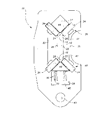
!I1 is an end elevation view of a track and rail-form
slider combination constructed in accordance with the teachings
of the present invention.
lItivRS Z is a side elevation view of the track and rail-
form slider combination illustrated in lIAEIRR 1.
The preferred embtxiiment, a track and rail-form slider
combination generally identified by reference numeral 10, will
now be described with reference to II~RER 1 and 2.
Referring to lit~JRE 1, the primary components of track and
rail-form slider combination 10 are a rail-form slider 12 in
combination with a track 14. Rail-form slider 12 has a top
surface 16, a bottom surface 18, and sides 20 and 22 extending
between top surface 16 and bottom surface 18. Rail-form slider
12 has four corners 24, 26, 28, and 30. Corners 24 and 26 are
formed where top surface 16 meets sides 20 and 22,
respectively. Corners 28 and 30 are formed where bottom
surface 18 meets sides 20 and 22, respectively. Track 14
includes a plurality of roller supports 32, only one of which
is illustrated. Roller support 32 is fabricated out of plate
steel. It has an generally rectangular central cavity 33,
access to which is provided through a side opening 35.
Adjoining central cavity 33 are an upper aperture 37 and a
lower aperture 39, the purpose of which will hereinafter be

CA 02121651 1999-09-13
4
further explained. Tabs 41 inwardly to partially obstruct side
opening 35. A mounting hole 43 is provided to facilitate the
mounting of roller support 32. Bight rollers 34 are provided
arranged in four pairs 36, 38, 40, 42. Pair of rollers 36, 38,
40 and 42 are mounted on roller assembly bars 44 and 46 in a
generally "V" shaped coafiguration. Upper roller assembly bar
44 has pairs of rollers 36 and 38 axially spaced along its
length. Lower roller assembly bar 46 has pairs of rollers 40
and 42 axially spaced along its length. Referring to ~'I
1, upper roller assembly bar 44 is secured by welding in upper
aperture 37 of roller support 32. Lower roller assembly bar
46 is positioned in lower aperture 39 of roller support 32 in
a fashion that enables it to "float" as will be hereinafter
further described. Referring to !'Ii~tJRE l, each roller 34
engages rail-form slider 12 solely at one of corners 24, 26,
28 and 30. Rollers 34 of pairs of rollers 24 and 26 from upper
roller assembly bar 44 are disposed at an angle of 45 degrees
relative top surface 16 of rail-form slider 12. Rollers 34 of
pairs of rollers 28 and 30 of lower roller assembly bar 46 are
disposed at an angle of 45 degrees relative bottom surface 18
of rail-form slider 12. A biasing block 48 is disposed below
lower roller assembly bar 46. A plurality of biasing springs
50 are disposed in pockets 52 in biasing block 48. Biasing
springs 50 bias lower roller assembly bar 46 into engagement
with rail-form slider 12. This results in roller assembly bar
46 moving in and out to accommodate imperfections in rail-form
slider 12. Referring to 1~I~ 3, guide pins 54 extend between
lower roller assembly bar 46 and biasing block 48. Guide pins
54 guide movement of lower roller assembly bar 46 relative to
biasing block 48.
The use and operation of track and rail-form slider
combination 10 will now be described with reference to ~'I6~URR8
1 and 2. A plurality of roller supports 32 are mounted by
means of mounting hole 43. Rail-form slider 12 is inserted
through side openings 35 of a plurality of roller supports 32
into central cavity 33. Pressure is exerted upon lower roller

CA 02121651 1999-09-13
assembly bar 4~ to coaapress springs 50 to permit rail-form
slider 12 to be positioned ~tween rollers 34. when in
position rollers 34 engage rail-form slider 12 solely at
corners 24, 26, 28 and 30. As rail-form slider 12 slides back
5 and forth oa rollers 34, springs 50 permit roller assembly bar
46 to move in and out to accommodate any imperfections. Should
rail-form slider 12 jua~ out from between rollers 34, tabs 41
prevent rail-form slider 12 from pawing back through side
opening 35.
It will be agpareat to one skilled in the art that with
rollers 34 engaging rail-form slider 12 solely at corners 24,
26, 28, aad 30, an accumulation of dirt and debris on top
surface 16 of rail-form slider will not adversely affect
operation. It will also be apparent to one skilled in the art
that rail-form slider is less prone to twisting when a force
is exerted that has a lateral component, due to the above
described corner engage~nt. It will also be apparent to one
skilled in the art that while 45 degrees is the preferred angle
for rollers 34, that rollers 34 are operable within an
operative range of between 30 degrees and 60 degrees. It will
finally be apparent to one skilled in the art that there are
other modifications that may be made to the illustrated
embodiment without departing from the spirit and scope of the
invention as hereinafter defined in the Claims.

Representative Drawing
A single figure which represents the drawing illustrating the invention.
Administrative Status

2024-08-01:As part of the Next Generation Patents (NGP) transition, the Canadian Patents Database (CPD) now contains a more detailed Event History, which replicates the Event Log of our new back-office solution.

Please note that "Inactive:" events refers to events no longer in use in our new back-office solution.

For a clearer understanding of the status of the application/patent presented on this page, the site Disclaimer , as well as the definitions for Patent , Event History , Maintenance Fee  and Payment History  should be consulted.

Event History

Description Date
Time Limit for Reversal Expired 2014-04-22
Letter Sent 2013-04-19
Inactive: Late MF processed 2012-06-15
Letter Sent 2012-04-19
Appointment of Agent Requirements Determined Compliant 2011-05-03
Inactive: Office letter 2011-05-03
Revocation of Agent Requirements Determined Compliant 2011-05-03
Inactive: Office letter 2011-04-28
Small Entity Declaration Determined Compliant 2009-03-04
Small Entity Declaration Request Received 2009-03-04
Inactive: Late MF processed 2008-06-30
Inactive: Correspondence - Formalities 2008-06-30
Letter Sent 2008-04-21
Inactive: IPC from MCD 2006-03-11
Grant by Issuance 1999-11-30
Inactive: Cover page published 1999-11-29
Small Entity Declaration Determined Compliant 1999-09-13
Inactive: Final fee received 1999-09-13
Inactive: Received pages at allowance 1999-09-13
Pre-grant 1999-09-13
Letter Sent 1999-03-12
Notice of Allowance is Issued 1999-03-12
Inactive: IPC assigned 1998-03-02
Inactive: IPC removed 1998-03-02
Inactive: First IPC assigned 1998-03-02
Inactive: Approved for allowance (AFA) 1998-01-29
Inactive: Status info is complete as of Log entry date 1997-11-05
Inactive: Application prosecuted on TS as of Log entry date 1997-11-05
All Requirements for Examination Determined Compliant 1996-01-30
Request for Examination Requirements Determined Compliant 1996-01-30
Application Published (Open to Public Inspection) 1994-09-25

Abandonment History

There is no abandonment history.

Maintenance Fee

The last payment was received on 1999-02-22

Note : If the full payment has not been received on or before the date indicated, a further fee may be required which may be one of the following

  • the reinstatement fee;
  • the late payment fee; or
  • additional fee to reverse deemed expiry.

Patent fees are adjusted on the 1st of January every year. The amounts above are the current amounts if received by December 31 of the current year.
Please refer to the CIPO Patent Fees web page to see all current fee amounts.

Fee History

Fee Type Anniversary Year Due Date Paid Date
Request for examination - small 1996-01-30
MF (application, 4th anniv.) - small 04 1998-04-20 1998-04-02
MF (application, 5th anniv.) - small 05 1999-04-19 1999-02-22
Final fee - small 1999-09-13
MF (patent, 6th anniv.) - small 2000-04-19 2000-03-31
MF (patent, 7th anniv.) - small 2001-04-19 2001-03-23
MF (patent, 8th anniv.) - small 2002-04-19 2002-02-04
MF (patent, 9th anniv.) - small 2003-04-22 2003-04-04
MF (patent, 10th anniv.) - small 2004-04-19 2004-02-25
MF (patent, 11th anniv.) - small 2005-04-19 2005-02-02
MF (patent, 12th anniv.) - small 2006-04-19 2006-02-27
MF (patent, 13th anniv.) - small 2007-04-19 2007-03-13
MF (patent, 14th anniv.) - small 2008-04-21 2008-06-30
Reversal of deemed expiry 2012-04-19 2008-06-30
MF (patent, 15th anniv.) - small 2009-04-20 2009-03-04
MF (patent, 16th anniv.) - small 2010-04-19 2010-02-18
MF (patent, 17th anniv.) - small 2011-04-19 2011-03-30
Reversal of deemed expiry 2012-04-19 2012-06-15
MF (patent, 18th anniv.) - small 2012-04-19 2012-06-15
Owners on Record

Note: Records showing the ownership history in alphabetical order.

Current Owners on Record
GOLDEN ROD WELDING LTD.
Past Owners on Record
DARRELL DOHERTY
Past Owners that do not appear in the "Owners on Record" listing will appear in other documentation within the application.
Documents

To view selected files, please enter reCAPTCHA code :


To view images, click a link in the Document Description column. To download the documents, select one or more checkboxes in the first column and then click the "Download Selected in PDF format (Zip Archive)" or the "Download Selected as Single PDF" button.

List of published and non-published patent-specific documents on the CPD .

If you have any difficulty accessing content, you can call the Client Service Centre at 1-866-997-1936 or send them an e-mail at CIPO Client Service Centre.


Document
Description 
Date
(yyyy-mm-dd) 
Number of pages   Size of Image (KB) 
Claims 1995-06-09 4 185
Description 1995-06-09 5 290
Abstract 1995-06-09 1 27
Drawings 1995-06-09 2 71
Drawings 1996-09-19 2 42
Description 1999-09-12 5 267
Abstract 1999-09-12 1 18
Claims 1999-09-12 4 143
Representative drawing 1998-08-24 1 22
Representative drawing 1999-11-21 1 12
Commissioner's Notice - Application Found Allowable 1999-03-11 1 164
Maintenance Fee Notice 2008-06-01 1 171
Maintenance Fee Notice 2008-06-01 1 172
Late Payment Acknowledgement 2008-08-24 1 164
Maintenance Fee Notice 2012-05-30 1 172
Late Payment Acknowledgement 2012-06-14 1 165
Maintenance Fee Notice 2012-05-30 1 172
Maintenance Fee Notice 2013-05-30 1 171
Fees 2003-04-03 1 25
Correspondence 1994-08-24 1 22
Correspondence 1999-03-11 1 102
Correspondence 1999-09-12 11 481
Fees 1998-04-01 1 42
Fees 1999-02-21 1 35
Fees 2004-02-24 1 29
Fees 2005-02-01 1 26
Fees 2006-02-26 1 25
Fees 2007-03-12 1 27
Correspondence 2008-06-29 3 110
Fees 2008-06-29 1 44
Fees 2009-03-03 2 70
Correspondence 2009-03-03 2 71
Fees 2010-02-17 1 200
Correspondence 2011-03-30 3 133
Correspondence 2011-04-27 1 12
Correspondence 2011-05-02 1 19
Fees 1997-01-23 1 38
Fees 1996-01-29 1 41