Sélection de la langue

Search

Sommaire du brevet 2121651 

Énoncé de désistement de responsabilité concernant l'information provenant de tiers

Une partie des informations de ce site Web a été fournie par des sources externes. Le gouvernement du Canada n'assume aucune responsabilité concernant la précision, l'actualité ou la fiabilité des informations fournies par les sources externes. Les utilisateurs qui désirent employer cette information devraient consulter directement la source des informations. Le contenu fourni par les sources externes n'est pas assujetti aux exigences sur les langues officielles, la protection des renseignements personnels et l'accessibilité.

Disponibilité de l'Abrégé et des Revendications

L'apparition de différences dans le texte et l'image des Revendications et de l'Abrégé dépend du moment auquel le document est publié. Les textes des Revendications et de l'Abrégé sont affichés :

  • lorsque la demande peut être examinée par le public;
  • lorsque le brevet est émis (délivrance).
(12) Brevet: (11) CA 2121651
(54) Titre français: CHEMIN DE ROULEMENT ET PIECE COULISSANTE COMBINES
(54) Titre anglais: TRACK AND RAIL-FORM SLIDER COMBINATION
Statut: Périmé et au-delà du délai pour l’annulation
Données bibliographiques
(51) Classification internationale des brevets (CIB):
  • B66C 09/10 (2006.01)
  • A63G 21/00 (2006.01)
  • B61B 03/00 (2006.01)
(72) Inventeurs :
  • DOHERTY, DARRELL (Canada)
(73) Titulaires :
  • GOLDEN ROD WELDING LTD.
(71) Demandeurs :
  • GOLDEN ROD WELDING LTD. (Canada)
(74) Agent: NATHAN V. WOODRUFFWOODRUFF, NATHAN V.
(74) Co-agent:
(45) Délivré: 1999-11-30
(22) Date de dépôt: 1994-04-19
(41) Mise à la disponibilité du public: 1994-09-25
Requête d'examen: 1996-01-30
Licence disponible: S.O.
Cédé au domaine public: S.O.
(25) Langue des documents déposés: Anglais

Traité de coopération en matière de brevets (PCT): Non

(30) Données de priorité de la demande: S.O.

Abrégés

Abrégé français

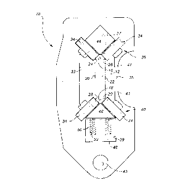
Un chemin de roulement et une pièce coulissante combinés sont décrits qui comportent une pièce coulissante ayant une surface supérieure, une surface inférieure, et des côtés s'étendant entre la surface supérieure et la surface inférieure. Des angles de versement sont formés à l'emplacement où la surface supérieure touche les côtés et où la surface inférieure touche les côtés. Un chemin de roulement est prévu qui comporte une pluralité de supports de roulement. Au moins quatre roulements sont fixés à chaque support de roulement. Chaque roulement n'entre en contact avec la pièce coulissante que dans les angles.


Abrégé anglais

A track and rail-form slider combination is described which includes a rail-form slider having a top surface, a bottom surface, and sides extending between the top surface and the bottom surface. Pour corners are formed where the top surface meets the sides and the bottom surface meets the sides. A track is provided which includes a plurality of roller supports. At least four rollers are secured to each roller support. Each roller engages the rail-form slider solely at one of the corners.

Revendications

Note : Les revendications sont présentées dans la langue officielle dans laquelle elles ont été soumises.


6
THE EMBODIMENTS OF THE INVENTION IN WHICH AN EXCLUSIVE PROPERTY
OR PRIVILEGE IS CLAIMED ARE DEFINED AS FOLLOWS:
1. A track and rail-form slider combination, comprising:
a. a rail-form slider having a top surface, a bottom
surface, aides extending between the top surface and the bottom
surface and four corners formed where the top surface meets the
sides and the bottom surface meets the sides; and
b. a track, including:
i. a plurality of roller supports;
ii. at least four rollers secured to each roller
support, each roller engaging the rail-form slider solely at
one of the corners.
2. The track and rail-form slider combination as defined in
Claim 1, wherein the at least four rollers are arranged in
pairs, each pair being mounted on a roller assembly bar in a
generally "V" shaped configuration.
3. The track and rail-form slider combination as defined in
Claim 2, wherein each roller assembly bar has two pairs of
rollers, each pair of rollers being axially spaced along the
roller assembly bar.
4. The track and rail-form slider combination as defined in
Claim 2, wherein biasing means are disposed between one of the
roller assembly bars and the roller supports, the biasing means
biasing the roller assembly bar into engagement with the
rail-form slider such that the roller assembly bar moves in and out
to accommodate imperfections in the rail-form slider.
5. The track and rail-form slider combination as defined in
Claim 1, wherein each roller is disposed at an angle of between
30 degrees and 60 degrees relative to one of the top surface
and the bottom surface of the rail-form slider.

7
6. The track and rail-form slider combination as defined in
Claim 5, wherein each roller is disposed at an angle of 45
degrees relative to one of the top surface and the bottom
surface of the rail-form slider.

8
7. A track and rail-form slider combination, comprising:
a. a rail-form slider having a top surface, a bottom
surface, sides extending between the top surface and the bottom
surface and four corners formed where the top surface meets the
sides and the bottom surface meets the sides; and
b. a track, including:
i. a plurality of roller supports;
ii. at least four rollers secured to each roller
support, each roller engaging the rail-form slider solely at
one of the corners with each roller disposed at an angle of
between 30 degrees and 60 degrees relative to one of the top
surface and the bottom surface of the rail-form slider, the
rollers being arranged in pairs, each pair being mounted on a
roller assembly bar in a generally "V" shaped configuration;
and
iii. at least one biasing spring disposed between
one of the roller assembly bars and the roller supports, the
biasing spring biasing the roller assembly bar into engagement
with the rail-form slider such that the roller assembly bar
moves in and out to accommodate imperfections in the rail-form
slider.
8. The track and rail-force slider combination as defined in
Claim 7, wherein each roller assembly bar has two pairs of
rollers, each pair of rollers being axially spaced along the
roller assembly bar.
9. The track and rail-form slider combination as defined in
Claim 7, wherein each roller is disposed at an angle of 45
degrees relative to one of the top surface and the bottom
surface of the rail-form slider.

9
10. A track and rail-form slider combination, comprising:
a. a rail-form slider having a top surface, a bottom
surface, sides extending between the top surface and the bottom
surface and four corners formed where the top surface meets the
sides and the bottom surface meets the sides; and
b. a track, including:
i. a plurality of roller supports;
ii. eight rollers secured to each roller support,
each roller engaging the rail-form slider solely at one of the
corners with each roller disposed at an angle of 45 degrees
relative to one of the top surface and the bottom surface of
the rail-form slider, the rollers being arranged in pairs, each
pair being mounted on a roller assembly bar in a generally "V"
shaped configuration, each roller assembly bar having two pairs
of rollers axially spaced along the roller assembly bar; and
iii. a biasing block being disposed below the roller
assembly bar the rollers of which engage the bottom surface of
the rail-form slider, a plurality of biasing springs being
disposed in pockets in the biasing block, the biasing springs
biasing the roller assembly bar the rollers of which engage the
bottom surface of the rail-form slider into engagement with the
rail-form slider such that the roller assembly bar moves in and
out to accommodate imperfections in the rail-form slider.

Description

Note : Les descriptions sont présentées dans la langue officielle dans laquelle elles ont été soumises.


CA 02121651 1999-09-13
The present invention relates to a track and rail-form
slider combination.
A variety of safety and lifting systems anchor lines or
equip~ent overhead. When the job requires movement within a
defined area, some pans must be provided to move the anchoring
point. One manner of doing so involves the use of an overhead
track system in which is positioned a slider to which the lines
or equipment are anchored.
There are a variety of different configurations of track
and slider combinations. Oae that most closely resembles the
present invention uses a rail-form slider which is supported
by track members with rollers that engage the top surface and
the bottom surface of the rail-form slider. One problem
experienced with rail-form sliders is that dirt and dust tends
to accumulate on the top surface of the rail-form slider. The
build up of dirt and dust impedes the operation of the slider.
Another problem relates to the farce vectors exerted upon the
slider. In most applications the force exerted upon the slider
will have a lateral component. If this lateral component is
too great a twisting of the rail-form slider occurs which can
lead to the slider binding.
What is required is a track and rail-form slider
cc~abination that is lass susceptible to the above described
problems.
According to the present invention there is provided a
track and rail-form slider combination which is comprised of
a rail-form slider having a top surface, a bottom surface, and
sides extending between the top surface and the bottom surface.

CA 02121651 1999-09-13
2
Four corners are formed where the top surface meats the sides
and the bottom surface meats the sides. A track is provided
which includes a plurality of roller supports. At least four
rollers are secured to each roller support. Each roller
engages the rail-form slider solely at one of the corners.
Although beneficial results may be obtained through the
use of the track and rail-form slider co~bination, described
above, for ease of assembly it is preferred that the rollers
be arranged in pairs with each pair mounted on a roller
assembly bar in a generally "V" shaped configuration. The
rollers should ba disposed at an angle of between 30 degrees
and 60 degrees relative to one of the top surface and the
bottom surface of the rail-form slider. It is preferred that
each roller ba disposed at an angle of 45 degrees relative to
one of the top surface and the bottom surface of the rail-form
slider.
Although beneficial results may be obtained through the
use of the track and rail-form slider combination, as descrihed
above, greater stability can be obtained when each roller
assembly bar has two gaits of rollers axially spaced along the
roller assembly bar.
Although beneficial results may ba obtained through the
use of the track and rail-form slider combination, as described
above, another problem relates to the fabrication of the rail-
form slides. In order to have a rail-form slider that is long
enough, it is common for a number of rail sections to be
secured together, with fasteners, by welding or other means.
If care is not taken in the preparation of the joints between
these sections, imperfections and gaps at the joints between
rail sections impedes the operation of the slider. Even more
beneficial results may, therefore, be obtained when biasing
as3ans are disposed between one of the roller assembly bars and
the roller supports. The biasing mans biases the roller
assembly bar into engagement with the rail-form slider such
~.

CA 02121651 1999-09-13
3
that the roller assembly bar moves in and out to accommodate
imperfections in the rail-form slider.
Bids! D~CRI1~I08~ ~! TH3 1?R~111I8
These and other features of the invention will become more
apparent from the following description in which reference is
made to the appended drawings, whereins
!I1 is an end elevation view of a track and rail-form
slider combination constructed in accordance with the teachings
of the present invention.
lItivRS Z is a side elevation view of the track and rail-
form slider combination illustrated in lIAEIRR 1.
The preferred embtxiiment, a track and rail-form slider
combination generally identified by reference numeral 10, will
now be described with reference to II~RER 1 and 2.
Referring to lit~JRE 1, the primary components of track and
rail-form slider combination 10 are a rail-form slider 12 in
combination with a track 14. Rail-form slider 12 has a top
surface 16, a bottom surface 18, and sides 20 and 22 extending
between top surface 16 and bottom surface 18. Rail-form slider
12 has four corners 24, 26, 28, and 30. Corners 24 and 26 are
formed where top surface 16 meets sides 20 and 22,
respectively. Corners 28 and 30 are formed where bottom
surface 18 meets sides 20 and 22, respectively. Track 14
includes a plurality of roller supports 32, only one of which
is illustrated. Roller support 32 is fabricated out of plate
steel. It has an generally rectangular central cavity 33,
access to which is provided through a side opening 35.
Adjoining central cavity 33 are an upper aperture 37 and a
lower aperture 39, the purpose of which will hereinafter be

CA 02121651 1999-09-13
4
further explained. Tabs 41 inwardly to partially obstruct side
opening 35. A mounting hole 43 is provided to facilitate the
mounting of roller support 32. Bight rollers 34 are provided
arranged in four pairs 36, 38, 40, 42. Pair of rollers 36, 38,
40 and 42 are mounted on roller assembly bars 44 and 46 in a
generally "V" shaped coafiguration. Upper roller assembly bar
44 has pairs of rollers 36 and 38 axially spaced along its
length. Lower roller assembly bar 46 has pairs of rollers 40
and 42 axially spaced along its length. Referring to ~'I
1, upper roller assembly bar 44 is secured by welding in upper
aperture 37 of roller support 32. Lower roller assembly bar
46 is positioned in lower aperture 39 of roller support 32 in
a fashion that enables it to "float" as will be hereinafter
further described. Referring to !'Ii~tJRE l, each roller 34
engages rail-form slider 12 solely at one of corners 24, 26,
28 and 30. Rollers 34 of pairs of rollers 24 and 26 from upper
roller assembly bar 44 are disposed at an angle of 45 degrees
relative top surface 16 of rail-form slider 12. Rollers 34 of
pairs of rollers 28 and 30 of lower roller assembly bar 46 are
disposed at an angle of 45 degrees relative bottom surface 18
of rail-form slider 12. A biasing block 48 is disposed below
lower roller assembly bar 46. A plurality of biasing springs
50 are disposed in pockets 52 in biasing block 48. Biasing
springs 50 bias lower roller assembly bar 46 into engagement
with rail-form slider 12. This results in roller assembly bar
46 moving in and out to accommodate imperfections in rail-form
slider 12. Referring to 1~I~ 3, guide pins 54 extend between
lower roller assembly bar 46 and biasing block 48. Guide pins
54 guide movement of lower roller assembly bar 46 relative to
biasing block 48.
The use and operation of track and rail-form slider
combination 10 will now be described with reference to ~'I6~URR8
1 and 2. A plurality of roller supports 32 are mounted by
means of mounting hole 43. Rail-form slider 12 is inserted
through side openings 35 of a plurality of roller supports 32
into central cavity 33. Pressure is exerted upon lower roller

CA 02121651 1999-09-13
assembly bar 4~ to coaapress springs 50 to permit rail-form
slider 12 to be positioned ~tween rollers 34. when in
position rollers 34 engage rail-form slider 12 solely at
corners 24, 26, 28 and 30. As rail-form slider 12 slides back
5 and forth oa rollers 34, springs 50 permit roller assembly bar
46 to move in and out to accommodate any imperfections. Should
rail-form slider 12 jua~ out from between rollers 34, tabs 41
prevent rail-form slider 12 from pawing back through side
opening 35.
It will be agpareat to one skilled in the art that with
rollers 34 engaging rail-form slider 12 solely at corners 24,
26, 28, aad 30, an accumulation of dirt and debris on top
surface 16 of rail-form slider will not adversely affect
operation. It will also be apparent to one skilled in the art
that rail-form slider is less prone to twisting when a force
is exerted that has a lateral component, due to the above
described corner engage~nt. It will also be apparent to one
skilled in the art that while 45 degrees is the preferred angle
for rollers 34, that rollers 34 are operable within an
operative range of between 30 degrees and 60 degrees. It will
finally be apparent to one skilled in the art that there are
other modifications that may be made to the illustrated
embodiment without departing from the spirit and scope of the
invention as hereinafter defined in the Claims.

Dessin représentatif
Une figure unique qui représente un dessin illustrant l'invention.
États administratifs

2024-08-01 : Dans le cadre de la transition vers les Brevets de nouvelle génération (BNG), la base de données sur les brevets canadiens (BDBC) contient désormais un Historique d'événement plus détaillé, qui reproduit le Journal des événements de notre nouvelle solution interne.

Veuillez noter que les événements débutant par « Inactive : » se réfèrent à des événements qui ne sont plus utilisés dans notre nouvelle solution interne.

Pour une meilleure compréhension de l'état de la demande ou brevet qui figure sur cette page, la rubrique Mise en garde , et les descriptions de Brevet , Historique d'événement , Taxes périodiques et Historique des paiements devraient être consultées.

Historique d'événement

Description Date
Le délai pour l'annulation est expiré 2014-04-22
Lettre envoyée 2013-04-19
Inactive : TME en retard traitée 2012-06-15
Lettre envoyée 2012-04-19
Exigences relatives à la nomination d'un agent - jugée conforme 2011-05-03
Inactive : Lettre officielle 2011-05-03
Exigences relatives à la révocation de la nomination d'un agent - jugée conforme 2011-05-03
Inactive : Lettre officielle 2011-04-28
Déclaration du statut de petite entité jugée conforme 2009-03-04
Requête visant une déclaration du statut de petite entité reçue 2009-03-04
Inactive : TME en retard traitée 2008-06-30
Inactive : Correspondance - Formalités 2008-06-30
Lettre envoyée 2008-04-21
Inactive : CIB de MCD 2006-03-11
Accordé par délivrance 1999-11-30
Inactive : Page couverture publiée 1999-11-29
Déclaration du statut de petite entité jugée conforme 1999-09-13
Inactive : Taxe finale reçue 1999-09-13
Inactive : Pages reçues à l'acceptation 1999-09-13
Préoctroi 1999-09-13
Lettre envoyée 1999-03-12
Un avis d'acceptation est envoyé 1999-03-12
Inactive : CIB attribuée 1998-03-02
Inactive : CIB enlevée 1998-03-02
Inactive : CIB en 1re position 1998-03-02
Inactive : Approuvée aux fins d'acceptation (AFA) 1998-01-29
Inactive : Renseign. sur l'état - Complets dès date d'ent. journ. 1997-11-05
Inactive : Dem. traitée sur TS dès date d'ent. journal 1997-11-05
Toutes les exigences pour l'examen - jugée conforme 1996-01-30
Exigences pour une requête d'examen - jugée conforme 1996-01-30
Demande publiée (accessible au public) 1994-09-25

Historique d'abandonnement

Il n'y a pas d'historique d'abandonnement

Taxes périodiques

Le dernier paiement a été reçu le 1999-02-22

Avis : Si le paiement en totalité n'a pas été reçu au plus tard à la date indiquée, une taxe supplémentaire peut être imposée, soit une des taxes suivantes :

  • taxe de rétablissement ;
  • taxe pour paiement en souffrance ; ou
  • taxe additionnelle pour le renversement d'une péremption réputée.

Les taxes sur les brevets sont ajustées au 1er janvier de chaque année. Les montants ci-dessus sont les montants actuels s'ils sont reçus au plus tard le 31 décembre de l'année en cours.
Veuillez vous référer à la page web des taxes sur les brevets de l'OPIC pour voir tous les montants actuels des taxes.

Historique des taxes

Type de taxes Anniversaire Échéance Date payée
Requête d'examen - petite 1996-01-30
TM (demande, 4e anniv.) - petite 04 1998-04-20 1998-04-02
TM (demande, 5e anniv.) - petite 05 1999-04-19 1999-02-22
Taxe finale - petite 1999-09-13
TM (brevet, 6e anniv.) - petite 2000-04-19 2000-03-31
TM (brevet, 7e anniv.) - petite 2001-04-19 2001-03-23
TM (brevet, 8e anniv.) - petite 2002-04-19 2002-02-04
TM (brevet, 9e anniv.) - petite 2003-04-22 2003-04-04
TM (brevet, 10e anniv.) - petite 2004-04-19 2004-02-25
TM (brevet, 11e anniv.) - petite 2005-04-19 2005-02-02
TM (brevet, 12e anniv.) - petite 2006-04-19 2006-02-27
TM (brevet, 13e anniv.) - petite 2007-04-19 2007-03-13
TM (brevet, 14e anniv.) - petite 2008-04-21 2008-06-30
Annulation de la péremption réputée 2012-04-19 2008-06-30
TM (brevet, 15e anniv.) - petite 2009-04-20 2009-03-04
TM (brevet, 16e anniv.) - petite 2010-04-19 2010-02-18
TM (brevet, 17e anniv.) - petite 2011-04-19 2011-03-30
Annulation de la péremption réputée 2012-04-19 2012-06-15
TM (brevet, 18e anniv.) - petite 2012-04-19 2012-06-15
Titulaires au dossier

Les titulaires actuels et antérieures au dossier sont affichés en ordre alphabétique.

Titulaires actuels au dossier
GOLDEN ROD WELDING LTD.
Titulaires antérieures au dossier
DARRELL DOHERTY
Les propriétaires antérieurs qui ne figurent pas dans la liste des « Propriétaires au dossier » apparaîtront dans d'autres documents au dossier.
Documents

Pour visionner les fichiers sélectionnés, entrer le code reCAPTCHA :


Pour visualiser une image, cliquer sur un lien dans la colonne description du document. Pour télécharger l'image (les images), cliquer l'une ou plusieurs cases à cocher dans la première colonne et ensuite cliquer sur le bouton "Télécharger sélection en format PDF (archive Zip)" ou le bouton "Télécharger sélection (en un fichier PDF fusionné)".

Liste des documents de brevet publiés et non publiés sur la BDBC .

Si vous avez des difficultés à accéder au contenu, veuillez communiquer avec le Centre de services à la clientèle au 1-866-997-1936, ou envoyer un courriel au Centre de service à la clientèle de l'OPIC.


Description du
Document 
Date
(aaaa-mm-jj) 
Nombre de pages   Taille de l'image (Ko) 
Revendications 1995-06-09 4 185
Description 1995-06-09 5 290
Abrégé 1995-06-09 1 27
Dessins 1995-06-09 2 71
Dessins 1996-09-19 2 42
Description 1999-09-12 5 267
Abrégé 1999-09-12 1 18
Revendications 1999-09-12 4 143
Dessin représentatif 1998-08-24 1 22
Dessin représentatif 1999-11-21 1 12
Avis du commissaire - Demande jugée acceptable 1999-03-11 1 164
Avis concernant la taxe de maintien 2008-06-01 1 171
Avis concernant la taxe de maintien 2008-06-01 1 172
Quittance d'un paiement en retard 2008-08-24 1 164
Avis concernant la taxe de maintien 2012-05-30 1 172
Quittance d'un paiement en retard 2012-06-14 1 165
Avis concernant la taxe de maintien 2012-05-30 1 172
Avis concernant la taxe de maintien 2013-05-30 1 171
Taxes 2003-04-03 1 25
Correspondance 1994-08-24 1 22
Correspondance 1999-03-11 1 102
Correspondance 1999-09-12 11 481
Taxes 1998-04-01 1 42
Taxes 1999-02-21 1 35
Taxes 2004-02-24 1 29
Taxes 2005-02-01 1 26
Taxes 2006-02-26 1 25
Taxes 2007-03-12 1 27
Correspondance 2008-06-29 3 110
Taxes 2008-06-29 1 44
Taxes 2009-03-03 2 70
Correspondance 2009-03-03 2 71
Taxes 2010-02-17 1 200
Correspondance 2011-03-30 3 133
Correspondance 2011-04-27 1 12
Correspondance 2011-05-02 1 19
Taxes 1997-01-23 1 38
Taxes 1996-01-29 1 41