Note: Descriptions are shown in the official language in which they were submitted.
w~ y~/u~q~
212190~
"COOLING SYSTEM'
THIS INVENTION relates to cooling systems, but in
particular relates to water coolers for drinking water.
Cooling systems are commonly used in many domestic,
commercial, or industrial situations where there is a need
or a desire for the provision of cold drinking water.
Water coolers in particular are traditionally fairly large
although this is often used advantageously by designing
aesthetically pleasing bodies or stands.
.
Water coolers in particular generally come in two forms;
those that have an upper inverted bottle of water and a
lower stand or body, and those that are supplied with mains
water and thus simply have a body with an upper drinking
spout or the like.
Traditionally, both of these types of water coolers have
used standard refrigeration components such as a
compressor, an evaporator, a condenser and a thermostat.
The compressor compresses vapour into a high pressure gas
which is then condensed into a liquid in the condenser.
The high pressure liquid is then expanded in the evaporator
and absorbs heat as it changes state. The thermostat
controls the temperature of the medium being cooled by
switching the compressor on and off as required.
Typically, these systems run for only 6 to 10 hours per day
and require comparatively large amounts of energy to run
and large amounts of space to house the apparatus.
The cooling system of the present invention utilises a
different principle to that described above. The present
invention is characterised by a cooling system which
produces ice and then uses energy stored in the ice to cool
a liquid. In this respect, and as indicated above, the
I W093/08432 212 19 0 a PCT/AU92/00~60
-- 2
cooling system is most advantageously used as a water
cooler.
The basic operating principle responsible for the
production of the ice in the cooling system of the present
invention is that of a thermoelectric cooler. This
principle, commonly called the Peltier effect, relies on
the absorption or generation of heat as a current passes
through a junction of two dissimilar conductive materials.
In any thermoelectric module there are two metal interfaces
which provide two functions. Firstly, the cold-side
interface absorbs heat from the medium to be cooled while
the hot-side interface dissipates heat to another medium,
typically ambient air via a heat sink such as a vaned
baffle. Secondly, the interfaces enable the module itself
to be sealed into a plastic housing, as thermoelectric
modules are readily degraded by condensation.
Thus, the present invention provides a cooling system which
produces ice and then uses the energy stored in the ice to
cool a liquid, the cooling system having a supply of liquid
in fluid communication with a cooling chamber, there being
an ice producing means located at least partially within
the cooling chamber, the ice producing means including a
thermoelectric module having a cold-side interface and a
hot-side interface, the cold-side interface being in direct
or indirect communication with liquid in the cooling
chamber and the hot-side interface being located externally
of the cooling chamber and being connected to a hot-side
heat sink for the dissipation of heat generated there~y,
and a power supply-being connected to the thermoelectric
module, wherein as heat is absorbed from the liquid by the
cold-side interface, local freezing of the liquid
immediately about the cold-side interface occurs and ice is
produced thereon.
W093/0~32 21219 0 j PCT/AU92/00~60
More particularly, the present invention provides a water
cooler having a supply of drinking water in fluid
communication with a cooling chamber, there being an ice
producing means located at least partially within the
cooling chamber, the ice producing means including a
thermoelectric module having a cold-side interface and a
hot-side interface, the cold-side interface being in direct
or indirect communication with water in the cooling chamber
and the hot-side interface being located externally of the
cooling chamber and being connected to a hot-side heat
sink for the dissipation of heat generated thereby, and a
power supply being connected to the thermoelectric module,
wherein as heat is absorbed from the water by the cold-side
interface, local freezing of the water immediately about
the cold-side interface occurs and ice is generated
thereon.
In a preferred form of the invention, the cold-side
interface is indirectly in communication with the water,
there being a cooling surface and a cold-side heat sink
located intermediate the cold-side interface and the water.
For example, a copper disc may be fixed to the cold-side
interface so that the héat is absorbed through the disc to
form ice on the surface of the disc. Alternatively, an
aluminium block may define the cold-side heat sink and the
surface of the block will then be the cooling surface. In
this form, the surface may include a stainless steel face
to assist in preventing corrosion.
The water cooler preferably also includes a sensing means
in the form of a photo-optic sensing device, to determine
when the ice produced is large enough to be released into
the cooling chamber. However, it will be appreciated that
other forms of sensing devices, such as an ultra-sonic
sensing device may be utilised.
W093/08432 2 1 21 ~ ~ ~ PCT/AU92/00~60
_, .
Once the first block of ice is released, the thermoelectric
module produces a second block of ice which ultimately is
also released, and so on. In this way, the cooling chamber
is filled with ice and water and as the heat of the water
is absorbed by the ice (thus melting the ice), the
temperature of the water is reduced. The water cooler thus
provides cooled drinking water by producing ice.
The photo-optic sensing device is preferably an infrared
beam of light capable of being received by a sensor such as
a photo transistor. The sensing device is preferably
configured so that the beam of light passes over the cold-
side inte~face of the thermoelectric module (or the cooling
surface if utilise~j within the cooling chamber. In this
respect, reference to the cold-side interface in the
following description is to be understood to refer to that
part of the ice producing means that is in contact with the
water although in the most preferred embodiment of the
present invention that will be the cooling surface.
An infrared beam is preferred as this is not effected by
ambient or white light which may enter the cooling chamber,
howe~er, the sensing device may use other light forms or
varying wave lengths as necessary and if required.
, - .
The beam preferably passes over the cold-side interface at
a height considered suitable for a corresponding thickness
of ice. As the ice grows, the beam is broken and the
sensor switches the power supply to the thermoelectric
module off.
By switching the power to the module off, heat is allowed
to ~low from the heat sink back through the hot-side
interface to the cold-side interface. The cold-side
interface rises in temperature until it defrosts a thin
layer of ice immediately adjacent thereto. The ice block
thus created floats towards the surface of the water,
W093/08432 2121~ O~ PCT/AU92/00~6~
_ - 5 -
moving out of the infrared beam and thus switching the
power to the module back on to begin generation of the next
block of ice.
It will be understood that when the cooling chamber is full
of ice, the infrared beam will remain broken and thus the
power to the module will remain off. Once a sufficient
amount of ice has melted, the power to the module will be
turne~ back on by the return of the infrared beam.
:
The water cooler of the present invention has been found to
be capable of cooling drinking water to between 1~ and 3~
Celsius. However, water at this temperature is often
considered unacceptably cold. Therefore, it is preferred
to warm the water somewhat before it is dispensed.
In a preferred form, the water cooler of this invention may
also include a water mixing device which allows
preferential mixing of an amount of the incoming ambient
water with the cooled water of the cooling chamber.
Further, the water cooler of this invention may also
include an ice dispersing means located above the
thermoelectric module to assist in dispersing the released
ice blocks throughout the body of the cooling chamber to
prevent an uneven stacking of those ice bloc~s. The ice
dispersing means is preferably configured to be a part o~ a
water baffle cap which is preferably provided to separate
an inverted water bottle (where that is used as the supply
of water) from the cooling chamber. The water baffle cap
also serves to prevent the ice generated from flowing into
the bottle which would displace water and possibly cause
flooding, and it also prevents the water in the bottle from
itself becoming too cold. In this respect, the cooling
chamber is an insulated chamber and thus is generally
unaffected by outside conditions. However, this is not the
case for the water bottle and any energy in the water
2 1 2 1 905
bottle in the form of cold water would be lost quite
rapidly. Furthermore, the water m; Y; ng device referred to
above may also be incorporated into the water baffle-cap
so that water may be drawn for dispensing from both above
and below the water baffle cap as required.
However, in an alternative form the need for an ice
dispersing means may be avoided by configuring the
cooling surface of the ice producing means such that the
ice blocks formed are unlikely to stack together. For
instance, rather than simply providing a flat cooling
surface, a generally concave surface may be provided,
preferably being substantially conical in configuration.
Other a~pects of this invention are as follows:
A water cooler which produces ice and then uses the
energy stored in the ice to cool dr; nk; ng water, the
water cooler having a supply of dr; nk; ng water in fluid
communication with a cooling chamber, there being an ice
producing means located at least partially within the
cooling cha~her~ the ice producing means including a
thermoelectric module having a cold-side interface and a
hot-side interface, the cold-side interface being in
communication with water in the cooling chamber and the
hot-side interface being located externally of the
cooling chamber and being connected to a hot-side heat
sink for the dissipation of heat generated thereby, the
water cooler also including a power supply connected to
the thermoelectric module, and a sensing means, wherein
as heat is absorbed from the water by the cold-side
interface, local freezing of the water immediately about
the cold-side interface occurs and ice is produced
thereon, the sensing means being capable of determining
when ice of a predetermined dimension has been formed on
2121905
the cold-side interface and controlling the power supply
to interrupt cooling of the cold-side interface until the
ice releases from the cold-side interface and is clear of
the sensing means.
A cooling system which produces ice and then used the
energy stored in the ice to cool a liquid, the cooling
system having a supply of liquid in fluid cnmmlln;cation
with a cooling chamber, there being an ice producing
means located at least partially within the cooling
chamber, the ice producing means including a
thermoelectric module having a cold-side interface and a
hot-side interface, the cold-side interface being in
communication with liquid in the cooling chamber and the
hot-side interface being located externally of the
cooling chamber and being connected to a hot-side heat
sink for the dissipation of heat generated thereby, the
cooling system also including a power supply connected to
the thermoelectric module, and a sensing means, wherein
as heat is absorbed from the liquid by the cold-side
interface, local freezing of the liquid immediately about
the cold-side interface occurs and ice is produced
thereon, the sensing means being capable of determ;ning
when ice of a predetermined dimension has been formed on
the cold-side interface and controlling the power supply
to interrupt cooling of the cold-side interface until the
ice releases from the cold side interface and is clear of
the sensing means.
A method for cooling liquid, said method comprising
producing ice on or in relation to the cold-side
interface of a thermoelectric module, switching the power
to the thermoelectric module off when the ice reaches a
predetermined size thus allowing heat from the hot-side
212iqO5
- 6b -
interface to transfer to the cold-side interface to melt
a thin layer of ice adjacent thereto, allowing the ice to
release from the cold-side interface and transfer into a
cooling chamber filled with liquid to cool that liquid,
the power to the thermoelectric module being switched on
when the ice releases from the cold-side interface to
produce more ice thereon, wherein a sensing means is
provided to detect when the ice has reached the
predetermined size and to switch the power to the module
on and off.
The present invention will now be fully described in
relation to a preferred embodiment illustrated in the
accompanying drawings. However, it will be understood
that the following description is not to limit the
generality of the invention as described above.
In the drawings:
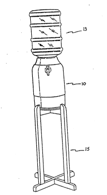
Figure 1 is a side view of a water cooler embodying the
invention in use; and
Figure 2 is a cross sectional view of a preferred
embodiment of the water cooler of Figure 1.
Illustrated in Figure 1 is a water cooler 10 having an
inverted water bottle 13 attached thereto, the assembly
of cooler and bottle being supported by a stand 15. It
will be understood that the present invention i~ only
related to the important aspects of the cooling system of
the water cooler 10.
Illustrated in Figure 2 is a water cooler 10 having a
cooling chamber 12, a dispensing outlet 14 and a water
bottle receiving neck 16. The cooling ch~mher 12 is
W093/0~432 PCTIAU~2~uu~
_ 7 2I 2I ~ 0~
substantially surrounded by insulating material 18 and is
within an outer shell 20 that may be constructed of any
preferred material, such as a ceramic material.
Located in the bottom wall 22 of the cooling chamber 12 is
the ice producing means generally indicated by the numeral
24. The ice producing means 24 comprises a thermoelectric
module 26 having a cold-side interface 28 which abuts a
cold side heat sink 30 which in turn has a cooling surface
32 in the form of a stainless steel face. The
thermoelectric module 26 also has a hot-side interface 34
~: which abuts and is connected to a hot side sink 36.
The ice producing means is virtually provided as a single
unit in the form of a cooling module 50 that includes
housings 52 for the sensing means 42 and may be moulded
with the cold-side heat sink 30 in place. The cooling
module ~0 may then be located within an appropriately sized
opening in the bottom wall 22 of the cooling chamber 12 and
secured thereto by an annular lock nut 54 threadably
received at the top end of the module 50.
The cooling module 50 may then be secured and sealed
against the upper domed portion 56 of the hot-side heat
sink 36, with the thermoelectric module 26 located in
abutment therebetween.
The hot-side sink 36 functions to remove heat from the
thermoelectric module 26 and is in the form of an aluminium
construction having fins arranged perpendicularly to a flat
base, thus being capable of radiating heat carried by the
fins away from the thermoelectric module. A fan 37 or the
like is preferably arranged to pass air across the surfaces
of the fins of the heat sink. It will also be understood
that the hot-side sink 36 may be made of materials other
than aluminium, such as copper and the like.
W093/0~432 PCT/AU92/00~60
212190i
-- 8
The cooling surface 32 has smoothly tapered surfaces so
that the ice block which is generated thereon during
operation of the water cooler will easily release therefrom
when the power supply to the thermoelectric module is
switched off. Furthermore, the cooling surface 32 is
concave, preferably in the general form of an inverted cone
as illustrated.
The power supply unit of the invention is not shown in the
drawing, but may be any suitable power supply which is able
to be located adjacent the ice generating apparatus 24 such
as at bolting points 38. Of course, the power supply unit
is c~n~cted to the sensing means 42 which is in the form
of a photo-optic sensing device which comprises a source of
an infra red beam. and a receiver of that infra red beam
such as a photo transistor. By drawing a line directly
between the two parts of the sensing means 42 it can be
seen that an ice block will be allowed to generate on the
cooling surface 32 to a predetermined thickness.
When in operation, the thermoelectric module 26 absorbs
heat from its cold-side interface 28 via the cold-side sink
30. Thus, heat from the cooling surface 32 is also
absorbed, creating a colder temperature in the cooling
surface than in the surrounding water. Thus, ice begins to
generate on the cooling surface 32.
Once the ice reaches a thickness where the infra red beam
of the sensing means 42 is broken, the sensor will switch
off the power supply. On switching off the power supply,
the heat generated within the heat sink 36 transfers
through the thermoelectric module 26 to the cold-side heat
sink 30 and subsequently to the cooling surface 32. A thin
layer of ice immediately adjacent to the cooling surface 32
begins to defrost until the ice block located on the
cooling surface 32 is able to break away therefrom. This
ice block will then float upwards towards the surface of
~ W093/0~32 2 1 2 1 9 ~ 5 PCT/A~92/00~60
the water in the cooling chamber 12. Once this ice block
has moved away from the sensing means 42, the power supply
will be turned back on by the sensor switch and the
thermoelectric module will again begin operating to cool
the cooling surface 32 and thus create another block of
ice. This procedure continues with a series of ice blocks
being created and released into the body of the cooling
chamber until the cooling chamber is full of ice blocks and
thus those ice blocks remain breaking the infra red beam.
Until some of those ice blocks melt to allow the ice blocks
at the bottom to move upwardly and out of the infra red
beam, the power supply will not be switched on and the
thermoelectric module will not reactivate to create more
ice. However, once the infra red beam is again clear,
further ice will be created.
The water cooler illustrated also includes a water baffle
cap 44. The water baffle cap 44 sits within the upper end
of the cooling chamber 12 and serves both to define the
water bottle receiving neck 16 and to separate the freshly
supplied water of the water bottle from the iced water
within the cooling chamber. Furthermore, the water baffle
cap 44 also includes a split outlet which provides a water
mi xi ng capability for mi xi ng the cooled water of the
cooling chamber 12 with the ambient water provided by the
water bottle -through neck 16. The provision of the water
mi xi ng capability is preferred in order that the cooled
water provided for drinking from the dispensing outlet 14
is not unacceptably cold. Thus, water is drawn from
immediately above the water baffle cap 44 to be mixed with
the cooled water from cooling chamber 12 upon operation Of
the dispensing outlet.
It will be appreciated that other features for providing
water mi X; ng capability devices or ice dispersing devices
may be utilised with the water cooler of the present
invention if necessary. It will also be appreciated that a
W093/0~32 PCT/AU92/00~60
-- 10 --
water cooler may be provided having any required external
configuration or any required configuration for joining or
sealing with a water bottle of any type.
It will further be appreciated that the water cooler of the
present invention may be readily adapted to be used with a
continuous water supply system such as a mains water supply
system. While some adaptation will be necessary, that
adaptation would nonetheless still utilise the inventive
concepts of the present invention.
Thus, the present invention provides a water cooler which
may be provided in an extremely compact form. Indeed, the
only part of the cooling apparatus that requires any
appreciable amount of space is in fact the heat sink on the
hot side interface of the thermoelectric module. However,
the heat sink required for this purpose is relatively small
compared to those required for normal refrigeration
facilities on traditional water coolers. Furthermore, the
water cooler of the present invention requires far less
energy to operate and is able to provide colder water more
consistently over a longer period of time. There are no
moving parts, apart from the fan, in the cooling apparatus
of the water cooler of this invention, and accordingly the
risk of failure or break down of the water cooler of this
invention is far less than traditional water coolers.
Furthermore, the water cooler of the invention does not use
any chlorofluorocarbon (CFC) gases which may deplete the
ozone layer, unlike conventional water coolers.
Those skilled in the art will appreciate that there may be
many variations and modifications of the configurations
described herein which are within the scope of the present
invention. In particular, it will be appreciated that the
concept of the invention may be extended for use in non-
drinking water cooling situations, such as in situations
where ice production by the above described method and
WO 93/08432 PCr/ A lJ ~J2i uu~ou
212190~
-- 11 --
apparatus would be advantageous, whether or not cooling of
a liquid is the end objective. Nonetheless, the major
advantage of the present invention lies in its use as a
water cooler as described.