Language selection

Search

Patent 2121907 Summary

Third-party information liability

Some of the information on this Web page has been provided by external sources. The Government of Canada is not responsible for the accuracy, reliability or currency of the information supplied by external sources. Users wishing to rely upon this information should consult directly with the source of the information. Content provided by external sources is not subject to official languages, privacy and accessibility requirements.

Claims and Abstract availability

Any discrepancies in the text and image of the Claims and Abstract are due to differing posting times. Text of the Claims and Abstract are posted:

  • At the time the application is open to public inspection;
  • At the time of issue of the patent (grant).
(12) Patent Application: (11) CA 2121907
(54) English Title: ULTRASONIC PROBE ASSEMBLY
(54) French Title: SONDE ULTRASONORE
Status: Dead
Bibliographic Data
(51) International Patent Classification (IPC):
  • A61B 8/12 (2006.01)
  • H04R 23/00 (2006.01)
(72) Inventors :
  • RELLO, MICHAEL J. (United States of America)
(73) Owners :
  • INTERSPEC, INC. (United States of America)
(71) Applicants :
(74) Agent: SIM & MCBURNEY
(74) Associate agent:
(45) Issued:
(86) PCT Filing Date: 1992-10-19
(87) Open to Public Inspection: 1993-04-29
Examination requested: 1998-10-09
Availability of licence: N/A
(25) Language of filing: English

Patent Cooperation Treaty (PCT): Yes
(86) PCT Filing Number: PCT/US1992/008909
(87) International Publication Number: WO1993/007808
(85) National Entry: 1994-04-21

(30) Application Priority Data:
Application No. Country/Territory Date
782,678 United States of America 1991-10-25

Abstracts

English Abstract

2121907 9307808 PCTABS00021
An ultrasonic probe assembly in which an ultrasonic transducer is
mechanically scanned in response to a drive motor which is
located in a housing spaced from the transducer such that the
transducer can be positioned in a body cavity of a patient while the
housing containing the drive motor remains outside the body of the
patient.


Claims

Note: Claims are shown in the official language in which they were submitted.


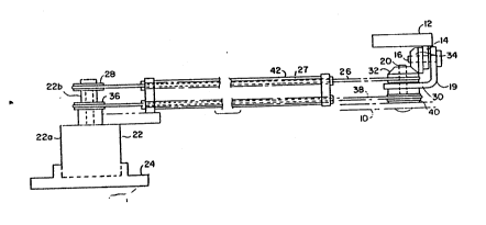
1. An ultrasonic probe assembly comprising:
a first housing (10);
an ultrasonic transduce (12);
first mounting means (14, 16) for mounting said
ultrasonic transducer for scanning movement of said
transducer in a selected scan plane about a first axis;
second mounting means (19, 20) for mounting said
first mounting means and said ultrasonic transducer to said
first housing for pivotal movement of said first mounting
means with respect to said first housing about a second axis
which is perpendicular to said first axis;
a second housing (21) spaced from said first
housing;
a drive motor (22) rotatably mounted in said
second housing and having a motor housing (22a) and an
output driver (22b);
selection means (24) attached to said motor
housing for setting a selected pivotal position of said
first mounting means corresponding to said selected scan
plane;
first coupling means (26, 27, 28, 30, 32, 34, 42,
50, 52, 54, 56, 58), including first flexible connecting
means (26, 27, 50, 52, 54, 56, 58), extending between said
output driver of said drive motor and said ultrasonic
transducer for imparting scanning movement to said
transducer in response to movement of said output driver,
said first flexible connecting means having a length which
permits positioning said first housing and said transducer
within a body cavity of a patient while said second housing
remains outside the body of the patient;

11

and second coupling means (27, 36, 38, 40, 42, 50,
52, 54, 56, 58), including second flexible connecting means
(27, 38, 50, 52, 54, 56, 58), extending between said
selection means and said second mounting means for
positioning said first mounting means in response to
movement of said selection means, said second flexible
connecting means having a length substantially coextensive
with said first flexible connecting means.

2. An ultrasonic probe assembly according to
claim 1 wherein said drive motor (22) is a reciprocating
motor and said scanning movement of said ultrasonic
transducer (12) is oscillatory.

3. An ultrasonic probe assembly according to
claim 2 further including a flexible tube (42) extending
between aid first housing (10) and said second housing (21)
and through which said first flexible connecting means (26,
27, 50, 52, 54, 56, 58) and said second flexible connecting
means (27, 38, 50, 52, 54, 56, 58) extend.

4. A ultrasonic probe assembly according to
claim 2 wherein the range of scanning movement of said
ultrasonic transducer (12) is one hundred degrees.

5. An ultrasonic probe assembly according to
claim 4 wherein the range of scan-plane variation of said
ultrasonic transducer (12) is one hundred eighty degrees.

6. An ultrasonic probe assembly according to
claim 1 wherein:
(a) said drive motor (22) is a reciprocating
motor,
(b) said scanning movement of said ultrasonic
transducer (12) is oscillatory,

12


(c) said first flexible connecting means (26, 27,
50, 52, 54, 56, 58) include:
(1) a first multi-strand steel cable section
(50) coupled to said ultrasonic transducer,
(2) a first single-strand steel music wire
section (52) attached to said first multi-
strand steel cable section,
(3) a first steel surgical tubing section
(54) attached to said first single-strand
steel music wire section,
(4) a first idler pulley (58), and
(5) a first endless belt (56) to which said
first steel surgical tubing section is
attached and which extends between said first
idler pulley and said output driver (22b) of
said driver motor, and
(d) said second flexible connecting means (27,
38, 50, 52, 54, 56, 58) include:
(1) a second multi-strand steel cable
section (50) coupled to said second mounting
means (19, 20),
(2) a second single-strand steel music wire
section (52) attached to said second multi-
strand steel cable section,
(3) a second steel surgical tubing section
(54) attached to said second single-strand
steel music wire section,
(4) a second idler pulley (53), and
(5) a second endless belt (56) to which said
second steel surgical tubing section is
attached and which extends between said

13


second idler pulley and said selection means
(24).
7. An ultrasonic probe assembly according to
claim 6 wherein:
(a) said first coupling means (26, 27, 28, 30,
32, 34, 42, 50, 52, 54, 56, 58) include:
(1) a first pulley (28) in said second
housing (21) fixed to said output driver
(22b) of said drive motor (22) and to
which said first endless belt (56) is
attached,
(2) a second pulley (30) in said first
housing (10) and to which said first
multi-strand steel cable section (50) is
attached,
(3) a first bevel gear (32) in said first
housing and integral with said second
pulley, and
(4) a second bevel gear (34) in said first
housing, meshing with said first bevel
gear and connected to said ultrasonic
transducer (12), and
(b) said second coupling means (27, 36, 38, 40,
42, 50, 52, 54, 56, 58) include:
(1) a third pulley (36) in said second
housing fixed to said selection means
(24) and to which said second endless
belt (56) is attached, and
(2) a fourth pulley (40) in said first
housing attached to said second mounting
means (19, 20) and to which said second

14

multi-strand steel cable section (SO) is
attached.

8. An ultrasonic probe assembly according to
claim 7 wherein said selection means include a rotatable
knob (24) fixed to said housing (22a) of said drive motor
(22).

9. An ultrasonic probe assembly according to
claim 2 wherein:
(a) said first coupling means (26, 27, 28, 30,
32, 34, 42, 50, 52, 54, 56, 58) further include:
(1) a first pulley (28) in said second
housing (21) fixed to said output driver
(22b) of said drive motor (22) and to which a
first end of said first flexible connecting
means (26, 27, 50, 52, 54, 56, 58) is
attached,
(2) a second pulley (30) in said first
housing (10) and to which a second end of
said first flexible connecting means is
attached,
(3) a first bevel gear (32) in said first
housing and integral with said second pulley,
and
(4) a second bevel gear (34) in said first
housing, meshing with said first bevel gear
and connected to said ultrasonic transducer
(12), and
(b) said second coupling means (27, 36, 38, 40,
42, 50, 52, 54, 56, 58) further include:
(1) a third pulley (36) in said second
housing fixed to said selection means (24)
and to which a first end of said second


flexible connecting means (27, 38, 50, 52,
54, 56, 58) is attached, and
(2) a fourth pulley (40) in said first
housing attached to said second mounting
means (19, 20) and to which a second end of
said second flexible connecting means is
attached.

10. An ultrasonic probe assembly according to
claim 1 wherein:
(a) said first flexible connecting means (26, 27,
50, 52, 54, 56, 58), include:
(1) first and second flexible connection
lengths (26) coupling said output driver
(22b) of said motor (22) to said ultrasonic
transducer (12), and
(2) first and second sleeves (27) through
which said first and said second flexible
connection lengths of said first flexible
connecting means, respectively, extend and
having a length substantially coextensive
with said first and said second flexible
connection lengths of said first flexible
connecting means, and
(b) said second flexible connecting means (27,
38, 50, 52, 54, 56, 58) include:
(1) first and second flexible connection
lengths (38) coupling said selection means
(24) to said second mounting means (19, 20),
and
(2) first and second sleeves (27) through
which said first and said second flexible
connection lengths of said second flexible
connecting means, respectively, extend and

16

having a length substantially coextensive
with said first and said second flexible
connection lengths of said second flexible
connecting means.

11. An ultrasonic probe assembly according to
claim 10 wherein opposite ends of said first and said second
sleeves (27) of said first flexible connecting means (26,
27, 50, 52, 54, 56, 58) and opposite ends of said first and
said second sleeves (27) of said second flexible connecting
means (27, 38, 50, 52, 54, 56, 58) are anchored in said
first (10) and said second (21) housings.

12. An ultrasonic probe assembly comprising:
a first housing (10);
an ultrasonic transducer (12);
mounting means (14, 16) for mounting said
ultrasonic transducer to said first housing for scanning
movement of said transducer;
a second housing (21) spaced from said first
housing;
a drive motor (22) rotatably mounted in said
second housing and having an output driver (22b);
and coupling means (26, 27, 28, 30, 32, 34, 42,
50, 52, 54, 56, 58), including flexible connecting means
(26, 27, 50, 52, 54, 56, 58), extending between said output
driver of said drive motor and said ultrasonic transducer
for imparting scanning movement to said transducer in
response to movement of said output driver, said flexible
connecting means:
(a) including:
(i) a multi-strand steel cable section (50)
coupled to said ultrasonic transducer,

17
(ii) a single-strand steel music wire section
(52) attached to said multi-strand steel
cable section,
(iii) a steel surgical tubing section (54)
attached to said single-strand steel music
wire section,
(iv) an idler pulley (58), and
(v) an endless belt (56) to which said steel
surgical tubing section is attached and which
extends between said idler pulley and said
output driver of said drive motor, and
(b) having a length which permits positioning
said first housing and said transducer within
a body cavity of a patient while said second
housing remains outside the body of the
patient.

13. A ultrasonic probe assembly according to
claim 12 wherein said coupling means further include:
(a) a first pulley (28) in said second housing
(21) fixed to said output driver (22b) of
said drive motor (22) and to which a first
end of said flexible connecting means (26) is
attached,
(b) a second pulley (30) in said first housing
(10) and to which a second end of said
flexible connecting means (26) is attached,
(c) a first bevel gear (32) in said first housing
(10) and integral with said second pulley
(30), and
(d) a second bevel gear (34) in said first
housing (10), meshing with said first bevel

18

gear (32) and connected to said ultrasonic
transducer (12).

14. An ultrasonic probe assembly according to
claim 13 wherein said coupling means further include:
(a) a first pulley (28) in said second housing
(21) fixed to said output driver (22b) of
said drive motor (22) and to which said
endless belt (56) is attached,
(b) a second pulley (30) in said first housing
(10) and to which said multi-strand steel
cable section (50) is attached,
(c) a first bevel gear (32) in said first housing
(10) and integral with said second pulley
(30), and
(d) a second bevel gear (34) in said first
housing (10), meshing with said first bevel
gear (32) and connected to said ultrasonic
transducer (12).

15. An endoscope comprising:
an ultrasonic probe assembly according to claim 1
wherein said ultrasonic transducer (12) develops signals
representative of a body part being imaged;
a flexible tube (42) extending between said first
housing (10) and said second housing (21) and through which
said first flexible connecting means (26, 27, 50, 52, 54,
56, 58) and said second flexible connecting means (27, 38,
50, 52, 54, 56, 58) extend;
and means (46) for conducting said signals
developed by said ultrasonic transducer to signal processing
and imaging equipment.

Description

Note: Descriptions are shown in the official language in which they were submitted.


'WO ~3/07808 rCr/US92/089~9
_ 1 _
2121307


ULTRASONIC PROaE ASSEMBLY


TECHNICAI. FIELD

The pre~ent invention relates, in general, to
ultrasonic imagi~g a~d, in particular, to an ultra~onic
probe assembly with the ultrasonic tran.~ducer arranged
for insertion into a body cavity.

BACKGROUND OF THE INVENTION

Ultra~onic probe assemblies having ~h
ultrasonic transducer arranged for in~ertion into a body
cavity ~i.e. prostate probes, esophageal probes, vaginal
probes) are i~ widespread use. Typically, the ultrasonic
tran~ducer, the transducer mount mechanism and the motor
which imparts scanning movement to the ultrasonic
transducer are hou~ed at one end of an endo~cope. Power
to the motor and electrical signals, from which ~he i~aga
i~ developed, are conducted along wires extending through

W0~3~0780~ PCTtUS92/08~9
2 l 21~

the endoscope. In addition, for those ultra~onic probe
a~emblies arranged for multi-plane scanning, the cables
by which the scan plane of the ultrasonic transducer i~
changed mechanically extend through the endoscope to the
transducer mount mechanism ~rom a con~rol remote rom the
tran~ducer mount mechani3m.

It i~ apparent that the size~ of the ultrasonic
transducer, the transducer mount mechanism and the
scanning motor dictate the size of the housin~ inserted
into the body cavity. Often, the size of this hou~ing i8
too large for the desired applications of the ultra~onic
probe a~embly.

S~MMARY OF THE INVENTION

An ultrasonic probe assembly, constructed in
accordance with ~he present invention, includes a fir~t
housing, a ultrasonic transducer and mounting means for
mounting the ultrasonic ~ransducer to the first housing
for scanning movement of the ul~ra~onic transducer. Also
included in thi~ ultrasonic probe assembly are a second
housing spaced from the first housing, a drive motor
mounted in the second houqing and having an output
driver, and coupling means, including ~lexible connecting
mea~s, extending between the output driver, of the motor
and ~he ultra~onic transducer for imparting ~canning
movement to the ultrasonic transducer in respon~e to the
output dri~er. The ~lexible connec~ing means have a
length which penmits po~itioning the fir~t hou~ing with
the,ultra30nic transducer within a body cavity of a
patient while the second hou~ing remains outside ~he body
of ~he patient.

When the present invention i5 incorpsrated in a
multi-pl~ne imaging ultra30nic probe assembly, ~he

~ 093~07~08 PCT~US91/08~9
21213307

assembly alqo includes gecond mounting means for mounting
the first mounting means and the ultra~onic tran~ducer to
the fixst hou~ing for pivotal movement of the fir~t
mounting means abou`t an axis perpendicular to the axis
about which the ultrasonic tran~ducer i~ ~canned. ~180
included are election means at~ached to ~he ~econd
housing containing the drive motor for ~etting a selected
piYotal position of the first mounting means and second
couplin~ mean~, including second flexible connecting
means, extending be~ween the selection mean~ and the
second moun~ing means for posi~ioning the fir~ moun~ing
means in response to the selection means. The sec~nd
flexible co~necting ~eans have a length subs~antially
coextensiYe with ~he f~rs~ flexible connerting mean3.

BRIEF D~SCRIPTION OF THE DRAWINGS

Figure 1 ~ a top ~iew of one preferred
embodiment of an ul~rasonic probe a~sembly con8tructed in
accordance with ~he present ~nvention.

~ gure ~ is a side ~iew of the Figure 1
ultrasonic probe ag9embly .

Figuxe 3 i9 an end view of the Figures 1 and 2
ultrasonic probe as~embly.

Figure 4 i9 a ~ide view o the Figures 1 and 2
ultrasonic probe assembly with the ultraaonic transducer
positioned to scan in a plane different from ~ts scan
plane in Figures 1 and 2.
_
' Figure 5 is an end ~iew of the Figures 1 and 2
ultrasonic probe a~sembly wi~h the ul~ra~onic transducer
po8itioned to scan as illustrated in Figure 4.

WO 93/~780~ P(~US92/g890~ .
212190~
-- 4

Figure 6 is a plan view of an endoscope in
which the ultrasonic probe a89e~ y of Figures 1 ~hrough
5 can be incorporated.

Figures 7A and 7B are ~3ectional views which
illustrate in more detail and on a lar~er ~cale the
flexible connection.. between the two housings o~ the
ultrasonic probe a~aembly of Fi~ures 1 ~hrough 5
incorporated in the.endoscope of Figure 6.

DET~ILED DESC~IPTION OF THE INVE~TION

Referring to Figures 1 through 5, an
ultrasonic probe a~Qembly, constructed in accordance with
the present i~vention, include~ a first hou~ing 10, a
ultra30nic transducer 12 and first mounting mean~ for
mounting transducer 12 or scanning movement of
transducer 12 about a first axis. Ultrasonic ~ransducer
12 ca~ be of conventional construction and operation such
aB a 3.5 - 5 MHz transducer supplied by Echo Ul~ra~ound
and u~ed ~ypically for cardiac imaging. Ultraso~ic
.transducer 12 is attached to a leg 14 and i9 mQunted, for
the embodiment of the present invention being descri~ed,
by a pivo~ shaft 16 on which leg 14 is mounted and which
defines an axis for scanning movement of ultra~onic
transdurer 12. Figure 3 ~hows by dashed lines 12B and
r ' 12b the range o oscillatory scanning motion of
ultra~onic transducer 12. A double-ended arrow 17
define~ this range of motion which typically i~ 100
' degrees.

The fir~t mounti~g means and ~l~ra~onic
transducer 1~ are mounted to houqing 10 for pivstal
msvement of the first mounting means about a second axiq
which i~ perpendicular to the ~can axis o~ transducer 12.
Thi~ i~ accomplished by second mounting mean~ which, for

,
W093/07808 ~t]~ L~n~7, PCr/US92/08~9

- 5

he embodiment of the preQent invention being de-qcribed,
include a bracket 19 and a pivot shaf t 2 0 . By thi9
arrangement the plane of ~canning of ultrasonic
tran~ucer 12 can be changed so that the body part, such
as the heart, which i8 being imaged can be ~iewed in
different ways (i. e . in longitudinal and tran3ver~e
sections or any ~ectio~ in between). ~igures 4 and 5
8how ultrasonic tran~ducer 12 positioned to scan in a
plane different from the scan plane po~it~on of
ultra~onic transducer 12 in Figure~ 1, 2 and 3.

An ultrasonic probe assembly, con tructed in
accordance with the present in~ention, a~so include~ a
~econd housing 21 spaced from first housing 10 and a
dri~e motor 22 mounted in housing 21 and having a motor
hou~ing 22a and an output dri~er shaft 22b. Drive motor
22, which can be a DC reciprocating mo~or, provides the
driYe for oscillatory ~canning movement of ultrasonic
transducer 12. DriYe motor 22 i~ rotatably mounted in
housing 21, so that i~ can pivot when the scan plane of
ultraQonic transducer 12 i~ to he cha~ged.

Attached to motor housing 22a are selection
mean~, in the form of a ~nob 24, for setting a selected
pivotal po3ition of th~ fir~t mounting means in housing
10. The position of kno~ 24 and, there~ore, the position
of motor 22 de~ermine the ~can plane of ultra30nic
~ransducer 12.

An ultra~onic probe a~sembly, constructed in
accordance with ~he pre~ent invention, ~urther includes
f~rst coupling means extending between ou~put driver ::
shaft 22b of mo~or 22 and ultrasonic transducer 12 or
imparting scanning movement to transducer 12 in re~ponse
to o~cillatory movement of output driver ~haft 22b. The
f$rst coupling means include, for the embodiment of ~he
.present invention being described, a flexible connection

W093/07B08 PCT~US92/08~9
2 1 2 ~ 7

26, made up of two lengths, attached at a first end to a
drive pulley 28 which ~ 9 fixed to output driver shaft 22b
of motor 22. ~lexible connection 26 alBo i8 attached at
a ~econd end to a pulley 30 which iY mounted on pivot
~haft 20 for reciprocatiny movement. Each length of
flexible connec~ion 26 extends through a ~leeve 27 the
oppo~ite end~ of which are anchored in ou inga 10 and 21.
Integral with pulley 30 i~ a ~ir~t bevel gear 32 which
me~he~ with a second bevel gear 34 to which leg 14 i9
at a~hed. AB a result, the o~cillatory drive provided by
motor 22 i~ imparted to ultrasonic tran~ducer 12 through
drîve pulley 28, flexible connec~ion 26, pulley 30, bevel
gear~ 32 and 34, and leg 14. The len~th of flexible
connection 26 and the length of each sleeve penmit-
~positioning fir~t hou3ing 10 ~nd ultrasonic transducer 12
within a body ca~rity of a patient while ~3ec:0nd housing 21
wi h motor 22 remains outside the body of the patient.

An ultrasonic probe as~embly, cons~ructed in
accordance with the present invention, further includes
second coupling means extending between th~ ~can-plane
selection mean~ at hou.~ing 21 and the ~econd mounting
means at hou3ing 10 for positioning the firs~ mounting
mean~ a~ hou~ing 10 in response to movement of th~
selection means. The ~econd coupling m2ans include, for
the Pmbodiment of the present invention,being described,
a pulley 36 fixed to motor hou~ing 22a and a second
flexible connection 38 fixed at one end to pulley 36 and
at a second end to a pulley 40 which i~ integral with
bracket 19. A~ a result, a~ knob 24 is turned, as
-r,~presented by the double-ended arrow 41, this moYement
is imparted to bracket 19 through motor housing 22~,
pulley 36, flexible connection 38 and pulley 40 to change
the ~can plane of ultrasonic transducer 12. The range of
scan-plane Yariation can be up to one hundred ei~hty
degr~es. The length of flexible connection 38 i~

Wos~/07808 2 ~ 2 1 9 0 7 PCr/U~92/~9

- 7 -

substantially coextensive with flexible connection 26, 90
that knob 24 with housi~g 21 is outside ~he body of the
patient while housing 10 and ultra~onic tran~ducer 12 are
within a body caYity of the patient.

Preferably, flexible connection~ 26 and 38
extend through a flexible tube 42, the ends of which are
attached by uitable means to housings 10 and 21. In
addition, wire~ (not ~hown) which power ultra~onic
transducer 12 and conduct imaging signals from tran~ducer
12 extend through ~lexible tube 42.

Figure 6 illustrates the ultra~onic probe
as~embly of Figure~ 1 through 5 incorporated in an
endoscope. Housings 10 and 21 are connected by flexible
tube 42 ~hrough which flexible connections 26 and 38
extend. Knob 24 on housing 21 functions, as previou~ly
described, to change the scan plane of the ultra~onic
transducer in housing 10. The Brive motor (not shown in
Figure 6) is located in hou~ing 21~ A ~econd knob 44 on
hou~ing 2~ control~ bending of the end of the flexible
Pndo3cope upward, downward and sideways to penmit the end
of the endoscope to make turns a~ it is passed through
the body to the body cavity at which imaging i8 to take
place. The wires (not -qhown) which power the ultrasonic
transducer (not shown in Figure 6) and conduct imaging
signal~ from the tran~ducer extend to a connector 46
which is adapted for connection into suitable s~gnal
proce3-qing and im2ging equ~pment.

Referring to Figure~ 7A and 7~, which should be
viewed with the righ~-hand end o~ Figure 7A leading to
the left-hand end of Figure 7B, flexible connection 26
~rom the Figureq 1 through 5 ultrasonic probe assembly
can include a multi-atrand steel cable ~ect~on 50 which
i~ pinned to pulley 30. A~ the two lengths of multi-
atrand ~teel cable ~ection 50 to ei~her side of pulley 30

W093/07~08 21907 rcT/us92/08~9


are pulled or pu~hed in response to the reciprocating
movemen~ of output driver shaft 22b of motor 22, pulley
30 turn~.

Flexible connection 26 al50 include~ a ~ingle-
strand steel music wire section 52 which is but~-welded
to multi-~qtrand ~teel cable ~ection 50. ~t ~t~ opposite
end, single-~trand steel mu~ic wire section 52 i~
~oldered to a steel surgical tubing section 54.

Steel Yurgical tubing section 5~ i~ soldered to
an endles~ belt 56 which extend~ between pulley 28 and an
idl~r pulley 5B. With endles~ belt 56 pinned to pulley
28 and pulley 28 fixed to ou~put driver shaft 22b of
motor 22, as output driYer shaft 22~ reciprocates, ..
pulley 2 8 iB drive~ and also reciprocates to cause
endle~ belt 56 to undergo movement-~ in OppOB~ te
directions.

The arrangement of flexible connection 26 which
ha~ just been described resultq in a connection having
xeduced hysteresis and backla~h. Multi-strand ~teel
cable section 50 is ~ufficiently ~lexi~le to confonm to
the tight radii in housing 10. Single-strand ~teel music
wire ~ection 52 provides suffici~nt stiffnes~ and
rigidity 80 that it can be pushed in push/pull operation.
Steel surgical tubing section ~4 serves as'the inside
wiper for the seal at the transition ~rom wet to dry in
an endoscope. Endless belt 56, in conjunCtion wi~h idler
pulley 58, be3ides converting the rotary motion of output
dri~er shaft 22b of motor ~2 to linear motion3 adds
8tiffness and rigidity to effect push/pull motion.

Flexible connection 38, by which the scan plane
of ultrasonic tran~ducer 12 is changed, can be arxanged
similar to flexible connection 26 ~u5t de~crlbed.

,

WO93/07B08 rC~/US92/n89Q9
2121907
g

The foregoing has set forth an exemplary and
preferred embodiment of the present inventio~. It will
be under~tood, howe~er, that variou.q other alternative
embodim2nts will occur to those of ordinary ~kill in the
art without departure rom the spirit and 3COp~ of the
present invention.

Representative Drawing
A single figure which represents the drawing illustrating the invention.
Administrative Status

For a clearer understanding of the status of the application/patent presented on this page, the site Disclaimer , as well as the definitions for Patent , Administrative Status , Maintenance Fee  and Payment History  should be consulted.

Administrative Status

Title Date
Forecasted Issue Date Unavailable
(86) PCT Filing Date 1992-10-19
(87) PCT Publication Date 1993-04-29
(85) National Entry 1994-04-21
Examination Requested 1998-10-09
Dead Application 2001-10-19

Abandonment History

Abandonment Date Reason Reinstatement Date
2000-10-19 FAILURE TO PAY APPLICATION MAINTENANCE FEE

Payment History

Fee Type Anniversary Year Due Date Amount Paid Paid Date
Application Fee $0.00 1994-04-21
Maintenance Fee - Application - New Act 2 1994-10-19 $100.00 1994-04-21
Registration of a document - section 124 $0.00 1994-09-30
Maintenance Fee - Application - New Act 3 1995-10-19 $100.00 1995-07-26
Maintenance Fee - Application - New Act 4 1996-10-21 $100.00 1996-10-01
Maintenance Fee - Application - New Act 5 1997-10-20 $150.00 1997-09-18
Maintenance Fee - Application - New Act 6 1998-10-19 $150.00 1998-10-07
Request for Examination $400.00 1998-10-09
Maintenance Fee - Application - New Act 7 1999-10-19 $150.00 1999-09-29
Owners on Record

Note: Records showing the ownership history in alphabetical order.

Current Owners on Record
INTERSPEC, INC.
Past Owners on Record
RELLO, MICHAEL J.
Past Owners that do not appear in the "Owners on Record" listing will appear in other documentation within the application.
Documents

To view selected files, please enter reCAPTCHA code :


To view images, click a link in the Document Description column. To download the documents, select one or more checkboxes in the first column and then click the "Download Selected in PDF format (Zip Archive)" or the "Download Selected as Single PDF" button.

List of published and non-published patent-specific documents on the CPD .

If you have any difficulty accessing content, you can call the Client Service Centre at 1-866-997-1936 or send them an e-mail at CIPO Client Service Centre.


Document
Description 
Date
(yyyy-mm-dd) 
Number of pages   Size of Image (KB) 
Abstract 1995-08-19 1 46
Description 1995-08-19 9 427
Drawings 1995-08-19 5 113
Claims 1995-08-19 9 376
Cover Page 1995-08-19 1 23
Representative Drawing 1998-07-22 1 7
Fees 1999-09-29 1 51
PCT 1994-04-21 132 3,739
Assignment 1994-04-21 9 342
Prosecution-Amendment 1998-10-09 1 56
Prosecution-Amendment 1998-12-31 1 30
Fees 1998-10-07 1 52
Fees 1997-09-18 1 54
Fees 1996-10-01 1 43
Fees 1995-07-26 1 30
Fees 1994-04-21 1 46