Note: Descriptions are shown in the official language in which they were submitted.
49523CANlA
2122089
1--
MET~OD AND APPARAIIJS FOl~ APPLYING
A COATING MATERL~L TO A RECEIV~G SURFACE
TECHNICAL FIELD
The invention relates to a method and apparatus
for applyinq coating material to a receiving surface.
BACKGROUND OF THE INVENTION
It is often desirable to coat a substrate with a
coating material, such as ink or an adhesive, in a desired
location on the substrate. For example, pressure sensitive
adhesive tape includes a web substrate coated with a layer
of pressure sensitive adhesive. Similarly, POST-IT brand
repositionable notes, available from the Minnesota Mining
and Manufacturing Company of St. Paul, Minnesota, include
a substrate having a band of pressure sensitive adhesive
coated over a portion of the substrate. In these and other
fields, it is desirable to apply the coating material to
the substrate in a controlled manner.
One process o~ applying a coating material to a
substrate is known as gravure coating, and is illustrated
schematically in Figure 1. The process includes a supply
12 of a substrate 10, an application roller 14, and a
supply of coating material 18 through which the
application roller is drawn. Also shown are a backing
roller 19 that opposes the application roller, a doctor
blade 21 for wiping excess coating material from the
application roller, and a winding system having one or
more rollers 13 to draw the substrate between the
application roller and the backing roller. As shown in
Figure 2, the application roller includes a peripheral
surface 30 having a multitude of individual cells 32 that
are recessed from the peripheral surface of the
application roller. The cells may be arranged in any
pattern, as shown in Figure 3, wherein cells 32 are formed
in the peripheral surface at certain locations, and no
cells are formed in locations 34.
,, . - . . . ...
2~22089
~ he cells collect the coating material as the
application roller passes through the supply of coating
material, and thus the areas of the peripheral surface
without cells (e.g. locations 34) do not collect coating
material. If any residual coating material collects on the
peripheral surface of the application roller, doctor blade
21 wipes that material from the peripheral surface prior
to contact with the substrate.
When the substrate passes the application
interface between the application roller and the backing
roller, the material is drawn out of each of the cells
because the coating material has a greater affinity for
the substrate ~han for the application roller. The surface
speed of the application roller is matched to the speed of
the substrate, to enable complete removal of the coating
material from the individual cells. If the surface speed
of the substrate is greater than or less than that of the
surface of the application roller, the cells of the
application roller will not be entirely evacuated.
Incomplete evacuation of the cells is undesirable, because
the predetermined amount of coating material has not been
transferred to the substrate.
Gravure coating, while having its own utility,
is not easily modified to enable a thinner or thicker
layer of coating material to be applied to the substrate.
Because the cells on the peripheral surface have a fixed
size and shape, and because the speed of the application
roller and the substrate are matched, a particular
application roller consistently applies the same pattern
and thickness of coating material to the substrate. To
change the pattern or thickness of coating material that
is applied to the substrate, the application roller must
be removed and replaced with a coating roller having
different surface characteristics (e.a. more or less
cells, greater or smaller spacing between adjacent cells~
or deeper or more shallow cells). The coating process must
be halted while a new application roller is attached to
the coating apparatus, and roller replacement is therefore
- . . .
:: ~
'' ' ~.
- - - .:
:- .
. . : : . . .
2122089
-3-
costly and undesirable. It would therefore be desirable to
provide a method and apparatus for applying a coating
material in different amounts and in varying patterns,
without having to replace the application roller.
Planographic coating is similar to gravure
coating in some regards, and includes such coating methods
as flexography, lithography, and both wet and dry offset
coating. A notable difference between gravure coating and
planographic coating relates to the peripheral surface of
the application roller, and the manner in which the
_oating material is carried on that surface. Whereas
gravure coating uses an application roller having a
plurality of cells that are recessed from the peripheral
surface of the application roller, planographic coating
uses a pattern roller 50 having a multitude of island
portions 52 that are raised above peripheral surface 54,
as shown in Figures 4 and 5. The coating material 56 is
carried only on the outermost surface o~ each island
portion 52, and the pattern roller 50 contacts the
application roller 55 to transfer the coating material
thereto. The application roller then transfers coating
material 56 onto a substrate 58 in the desired pattern.
Although planographic coating also has certain
benefits, it is difficult to alter the coating parameters
~uickly and inexpensively. To change the pattern or
thickness of coating material applied to the substrate,
the pattern roller must typically be replaced, because the
characteristics of a particular pattern roller determine
the pattern and thickness of coating material that will be
applied to the substrate. Replacement of the pattern
roller must take place when the coating process is
stopped, and is therefore undesirable for the same reasons
as stated above with reference to gravure coating.
Furthermore, if several different pattern rollers must be
available for each coating apparatus to provide a desired
coating thickness or pattern, the investment in pattsrn
rollers may be substantial.
~122089
It is therefore desirable to provide a method
and apparatus for applying coating material to a
substrate, wherein the coating characteristics may be
altered without replacing the application roller.
SUMMARY OF THE INVENTION
The present invention includes an application
member for transferring a coating material from a supply
of such material to a receiving surface, and for applying
the material to the receiving surface. The application
member includes a hub having a central axis for rotation
thereabout, and having a generally cylindrical peripheral
surface, and a plurality of spaced, discrete structures
projecting from the peripheral surface of the hub.
Rotation of the hub about the central axis enables the
peripheral surface to pass a source of the coating
material to receive the coating material, and to carry the
coating material on the peripheral surface of the hub
between and on said projecting structures toward an
application interface to transfer the material from the
peripheral surface to the receiving surface. Also provided
is an application system for applying a coating material
to a receiving surface, including the application member
described above, and means for rotating said hub about the
central axis thereof at a predetermined angular velocity.
The rotating means enables the peripheral surface to pass
a source of the coating material to receive the coating
material and to carry the coating material on the
peripheral surface between and on said projecting
structures toward an application interface between the
peripheral surface and the receiving surface, and to
transfer said coating material to the receiving surface.
An increase in the angular velocity of the hub increases
the amount of coating material transferred to the
receiving surface, and a decrease in the angular velocity
of the hub decreases the amount of coating material
transferred to the receiving surface.
~22~89
-5-
In another aspect of the present invention, a
method is provided for applying a coating material to a
receiving surface. The method includes the steps of
providing a hub having a central axis of rotation, and
having a generally cylindrical peripheral surface
including a plurality of spaced, discrete structures
projecting from the peripheral surface; providing a source
of the coating material in sufficient proximity to the
peripheral surface to enable the peripheral surface to
receive the coating material and to carry the coating
material between and on said projecting structures;
contacting a receiving surface with the peripheral surface
of the hub at an application interface to enable the
peripheral surface to transfer the coating material to the
receiving surface at the interface; and rotating the hub
to receive the coating material from the material source
and to transfer the material to the receiving surface at
the application interface. Also provided is a substrate
coated with a coating material according to the method
described above.
A method is also provided for making an
application member for applying a coating material to a
receiving surface. The method includes the steps of
providing a hub having a generally cylindrical peripheral
surface; forming a plurality of discrete indentations in
the peripheral surface; and retaining a particle within
substantia~ly all of the indentations, such that a portion
of each particle projects above the peripheral surface of
the hub. Thus, the application member is adapted to carry
the coating material on and between the particles prior to
application to the recelving surface.
BRIEF DESCRIPTION OF THE DR~WINGS
The present invention will be described with
reference to the appended Figures, wherein like structure
is represented by like numbers throughout the several
views, and wherein:
-6- 21 22 089
Figure 1 is a schematic illustration of a
gravure coating process according to the prior art;
Figure 2 is a sectional view of a gravure
application roller according to the prior art;
Figure 3 is a plan view of the face of a gravure
application roller according to the prior art;
Figure 4 is a schematic illustration of a
planographic coating process according to the prior art;
Figure 5 is a plan view of the face of a
planographic transfer roller;
Figure 6 is a cross-sectional view of the
applicator apparatus of the present invention;
Figure 7 is a cross-sectional view of an
applicator roller according to the present invention,
including a layer of material coated over the outer
surface of the roller;
Figure 8 is a schematic representation of the
application of a material to a substrate, when the surface
velocity of the application roller is approximately equal
to the surface speed of the substrate;
Figure 9 is a schematic representation of the
application of material to a substrate, when the surface
velocity of the application roller is less than the
velocity of the substrate; and
Figure 10 is a schematic representation of the
application of material to a substrate, when the surface
velocity of t~e application roller is greater than the
velocity o~ the substrate.
DETAILED DESCRIPTION OF THE INVENTION
The present invention relates broadly to an
application member for applying a coating material ~o a
receiving surface. The coating material may be any
suitable material, including but not limited to adhesive
te.~. pressure sensitive adhesive) and ink. The receiving
surface may be, for example, a substrate, such a
continuous web of paper or polymeric material, or a belt
or roller that receives the material and transfers the
2122089
material to a substrate. Thus, the present invention,
although described primarily with reference to the
application of adhesive to a substrate, also has broad
applicability to other coating operations as well.
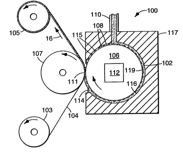
Figure 6 illustrates an applicator for applying
a coating material to a receiving surface. In the
illustrated embodiment, an appiicator apparatus 100 is
shown for applying an adhesive 102 to a substrate 104,
such as paper. The substrate is provided by supply roll
103, and is collected at collection roll 105. The
applicator includes a hub 106 having a generally
cylindrical peripheral surface 108 and a central axis
about which the hub is adapted to rotate. The hub is
rotatively supported at each end by support structure (not
shown). Substrate 104 is fed between backing roller 107
and hub 106, and adhesive 102 is applied to the substrate
104 at application interface 111.
Also provided is a source 110 of adhesive 102,
and means for rotating the hub about the central axis at a
predetermined rotational velocity. In the illustrated
embodiment, the rotating means comprises a motor 112. The
hub is supported proximate the adhesive source 110, such
that adhesive may be disposed on the peripheral surface of
the hub at a controlled rate. Also provided is a metering
bearing 114, which controls the amount of coating material
that is allowed to accumulate on the surface of the
application roller. Metering bearing 114 also seals
coating material reservoir 116, to prevent coating
material from leaking out of the reservoir. Reservoir 116
is preferably provided by a body 117 having a chamber 119
in which the application roller is rotatively supported,
although alternate configurations can be provided instead.
A particular feature of the present invention
relates to the topography of peripheral surface 108 of hub
106. The peripheral surface, in contrast to that of the
application rollers of the prior art, includes a~plurality
of spaced, discrete structures projecting from the
peripheral surface of the hub, between and on which
2~122089
structures the adhesive is carried. That is, the adhesive
coats the entire peripheral surface of the application
member, including the projecting structures. In one
embodiment, the projecting structures are generally
hemispherical, and measure on the order of 0.76 mm (0.003
in) high, relative to the remainder of the peripheral
surface. Projecting structures 115 may be regularly spaced
or irregularly spaced about the peripheral surface, and
may be hemispherical, square, triangular, or any other
suitable shape.
An exploded sectional view of a portion of the
application roller 106, peripheral surface 108, and
projecting structures 115 is shown in Figure 7. Adhesive
102 is carried both between projecting structures 115 (in
contrast to planographic application processes) and atop
projecting structures 115 (in contrast to gravure coating
processes). Metering bearing 114 controls the thickness of
the layer ~f adhesive coated over and between the
projecting structures.
At the application interface 111, adhesive 102
is transferred to substrate 104 as shown in Figure 8.
Application roller 106 is rotating with a surface velocity
V1 (the velocity of the surface at the application
interface), and substrate 104 is travelling with a
velocity V2 that is approximately equal to V1. Adhesive 1~2
is transferred to substrate 104 at the application
interface 111, because the adhesive has a greater affinity
for substrate 104 than for the peripheral surface 108 of
application roller 106. Projecting structures 115 prevent
adhesive from being transferred to substrate 104 at
imprints 120.
This peripheral surface topography and transfer
mechanism is believed to provide certain benefits. For
example, complete adhesive coverage of the substrate may
be achieved, and yet the adhesive surface 122 is
discontinuous. A discontinuous adhesive surface has
certain utility in conjunction with repositionable
substrates, because the object to which the substrate is
2122089
, g
applied is not fully contacted by the adhesive surface
122. By providing application rollers having greater or
fewer projecting structures, a greater or lesser
percentage of the adhesive surface will be interrupted by
imprints 120.
Another feature of the applicator of the present
invention relates to the ability to change the
characteristics o~ the adhesive layer without substituting
application rollers. For example, Figure 9 illustrates the
operation of the present application roller when the
surface velocity of the application roller Vl is less than
the velocity of the substrate V2. Adhesive 102 is applied
to substrate 104 as described previously, but because
projecting structures 115 are travelling more slowly than
substrate 104, the projecting structures tend to wipe
a~ay, or "sweep out" adhesive at imprints 120'. The degree
to which the projecting structures sweep out adhesive
depends on the difference in velocity between the roller
and the substrate at the interface, which may be desirable
for providing a repositionable substrate.
Another method of operating the applicator of
the present invention is illustrated in Figure 10, wherein
the surface velocity of the application roller V1 is
greater than the velocity of the substrate V2. Adhesive
102 is applied to substrate 104 as described previously,
but because projecting structures 115 are travelling
faster than substrate 104, the adhesive tends to build up,
or be "loaded" onto the substrate. Adhesive loading may be
beneficial because a thicker layer of adhesive may be
applied to the substrate merely by changing the operating
speed of the applicator roller, rather than having to
change application rollers as with the prior art.
Furthermore, adhesive surface 122'' is virtually devoid of
imprints, and thus the entire adhesive surface is
presented for contact with an object to which the
substrate is to be attached.
There are a legion of variations of the method
and apparatus described above. For example, the projecting
~` : `` ~ ; q; i ~ ~ ' 3 ~
2122089
1 0--
structures could be adapted to lightly contact the
substrate at the application interface, thereby preventing
any adhesive from being transferred to the substrate. The
rotational velocity of the application roller could be
altered during the production run, such that a portion of
a substrate is coated with a relatively large amount of
adhesive, and an adjacent portion is coated with a
relatively small amount of adhesive. Alternatively,
segments of the application roller can have different
sizes or densities of particles, or both, to produce lanes
or strips of different coating thicknesses, or different
surface contact areas, or both. These strips would extend
along the length of the substrate in generally parallel
fashion.
A further description of the topography of the
peripheral surface may be particularly described by the
process used to produce that surface. A hub with a
cylindrical peripheral surface was provided, where the
surface was made of steel and was machined to a relatively
smooth finish. The peripheral surface was then grit
blasted to produce a plurality of indentations in the
surface. The indentations were approximately hemispherical
with a radius of approximately 1.0 mm (0.004 in). After
the indentations were formed, spherical particles of
tungsten carbide (WO) [or nickel chromium] were impelled
against the surface, and were lodged within the
indentations due to the frictional force between the
particle and the edges of the indentations. A portion of
each of the particles projected above the peripheral
surface, which formed the projecting structures in the
peripheral surface of the application roller.
To facilitate the transfer of the adhPsive from
the peripheral surface to the receiving surface at the
application interface, a release coating was applied over
the peripheral surface of the hub. The release coating,
which comprised a fluorocarbon or TEFLON, was spray
applied over the entire peripheral surface of the hub. The
-ll- 21 22089
thickness of the release coating applied to the peripheral
surface was approximately 0.76 mm (O.003 in).
The foregoing method of making a hub according
to the present invention is intended to be illustrative,
rather than limiting. Other methods of providing
projecting structures on a peripheral surface, whereby a
coating material is carried between and on the structures,
will be apparent, and are intended to be within the scope
of the present invention.
Example
As an illustration of the method and apparatus
of the present invention, the application roller described
above was used to provide an adhesive coating on a
substrate. The substrate was 20 lb bond paper, and was
conveyed past the application roller at a velocity of
approximately 1.52 m/s (300 ft/min).
An adhesive comprising 84 grams of isooctyl
acrylate, 75 grams of octyl decyl acrylate (at 48% solids
in ethyl acetate), 121 grams of ethyl acetate, and 0.92
grams of 4-acryloyl-oxy-benzophenone (at 25% solids in
ethyl acetate) was prepared as follows. The components
were charged in a 500 ml, four-necked reaction vessel. The
reaction vessel was equipped with a stirrer, a
thermometer, a condenser, an addition funnel, and a
thermowatch. An solution of 0.36 grams catalyst of the
type available from the E.I. DuPont de Nemours Corporation
of Bloomington, Delaware under the designation "VAZO 64"
in 20 grams of ethyl acetate was added to the addition
funnel. Both the solution in the reaction vessel and the
materials in the addition funnel were then purged with
nitrogen. The solution in the reaction vessel was then
stirred and heated to 55 C and initiator was added. After
about 20 hours, a 98-99% conversion was obtained. After
drying, the adhesive was suitable for application to a
backing by the method and apparatus of the present
invention.
:.,' ' . . ... ` . ': ' ' . '
. . :,~ , ,
21~8~
r~ -12-
The application roller was rotated at a
rotational velocity sufficient to produce a surface
velocity approximately equal to that of the substrate -
approximately 2.4 m/s (300 ft/min). A metering bearing was
used to restrict the adhesive to a layer measuring
approximately 0.3 mm (0.0012 in) thick across the entire
surface of the applicator roller and projecting
structures. At the application interface, the material was
transferred to the surface of the paper, resulting in a
layer of adhesive measuring approximately 0.3 mm (0.0012
in) being disposed on the paper. The projecting structures
left a plurality of indentations in the adhesive layer,
corresponding to the size and spacing of the structures.
The paper coated with adhesive in this manner was useful
for application to a surface.
The rotational velocity of the application
roller was increased to produce a surface velocity of
approximately 2.03 m/s (400 ft/min), such that the ratio
between the surface velocity and substrate velocity was
approximately 4:3. The metering bearing was used to
restrict the adhesive to a layer measuring approximately
0.3 mm (0.0012 in) thick across the entire surface of the
applicator roller and projecting structures. ~t the
application interface, the material was transferred to the
surface of the paper.
Because the application roller was passing the
application interface at a greater speed than the
substrate, adhesive was coated on the substrate at a
greater thickness than on the application roller. The
resulting coating thickness on the substrate was
approximately 0.36 mm (0.0014 in), and the surface
comprised a compressed reverse image of the application
roller surface. That is, indentations or striae were
formed in the surface of the adhesive in a compressed
pattern due to adhesive loading. The paper coated with
adhesive in this manner was useful for application to a
surface.
i ~ .. . . . . ~ . . , .. . , ~ ; . ; .
, ~ -13-2122089
Finally, the rotational velocity of the
application roller was reduced to produce a surface
velocity of approximately 0.5 m/s (100 ft/min), such that
the ratio between the surface velocity and the substrate
velocity was approximately 1:3. The metering bearing was
used to restrict the adhesive to a layer measuring
approximately 0.3 mm (0.0012 in) thick across the entire
surface of the applicator roller and projecting
structures. At the application interface, the material was
transferred to the surface of the paper.
Because the application roller was passing the
application interface at a lesser speed than the
substrate, adhesive was coated on the substrate at a
lesser thickness than on the application roller. The
resulting coatin~ thickness on the substrate was
approximately 0.1 mm (0.0004 in), and the surface
comprised a stretched reverse image of the application
roller surface. That is, indentations or striae were
formed in the surface of the adhesive in an extended
pattern due to the difference in velocity between the
roller and paper.
An adhesive coating thickness of 0.00127 mm to
0.00381 mm (0.00005 in to 0.0015 in) was obtain2d, and the
adhesive coating was crosslinked by W radiation from a
25 FUSION brand F-600 W light source equipped with a 600
watt, 2.5 cm mercury halide bulb. The paper substrate was
passed beneath the W radiation station at a velocity of
approximately 1.52 m/s ~5.0 ft/s) to crosslink the
adhesive to prepare the sample for use. The paper coated
with adhesive in this manner was useful for application to
a surface.
In sum, the characteristics of the adhesive
layer applied to the substrate were changed significantly,
without necessitating a change in the application roller.
The present invention has been described with
reference to several embodiments thereof. However, persons
of skill in the art will recognize that variations may be
made in the embodiments described without departing from
. . . ... . :.. : ~ ,.;, , ;,, ~
2122Q89
-14-
the scope of the invention. Thus, the scope of the present
invention should not be limited by the embodiments shown
and described herein, but rather by the structures
described by the claims, and the equivalents of those
structures.
.
49523E~E7.SPC3