Note: Descriptions are shown in the official language in which they were submitted.
2122~7~
- ROCESS FOR CONVERSION OF A BOARD PRODUCTION PLANT
The invention relates to a process to convert a
chipboard, fibreboard and plywood production plant from a
dlscontinuous to a continuous mode of operation, in which the
existing single or multiple-stage press is replaced by a
continuously-operating press.
The continuous mode of operation has overtaken the ~ -
discontinuous mode in the manufacture of chipboard, fibreboard
and plywood in recent years. The reason for this probably
lies as much in the qualitative improvement of the prefinished ~ ~
`~ board, as in the more economical production with a lower price - ~-
and a higher degree of finishing. This reversal was achieved
through the use of continuously-operating presses, which
operate using two rotating roll-bar carpets as a support
between the heater plates and the steel belts of the press
plate and the ram. -
Such continuously-operating presses have become known
through patents DE-PS 923 172, DE-OS 22 15 615, DE-PS 31 17
778, DE-PS 31 40 548 and DE-OS 39 13 991. :
However, removal of the existing single or multiple-stage
press and installation of the new continuously-operating press
results in a long down-time for the board manufacturing plant,
which means major losses in income for the operators.
The purpose of the inyention is to create a process by
means of which the conversion of a board manufacturing plant -~
of the specified type from a discontinuous mode of operation
to a continuous mode can be accomplished in the shortest -~:
possible time.
According to one aspect of the invention, there is
provided a process to convert a chipboard, fibreboard or
plywood production plant from a discontinuous to a continuous
` mode of operation, in which an existing single or multiple-
stage press is replaced by a continuously-operating press, -:
characterized by the following procedures~
(I) during the operation of the existing press
equipment:-
A) setting up, as close as possible to the existing press, a
preassembly site with a roof ttent or shed) and a press
''' ','~'~
~ 21~217~
; - 2 -
foundation which has the capacity to support a continuously-
operating press which will be assembled;
B) completely assembling the continuously-operating press
with several predetermined individual modules Cn on
transportable assembly and transport bridges;
C) conducting a trial operation of the continuously-
operating press under load but without heating, including all
control functions; and
~ (II) after the existing press has been shut down:-
D) dismantling the discontinuously-operating press and
removing it from the production shed;
E) constructing the foundation in the production shed to
accept the continuously-operating press, at the same time, ~-
splitting up the continuously-operating press at the
interfaces, removing the steel belts and secure the loose -
- rotating production elements of the continuously-operating
~` press (l),
F) conveying the individual modules Cn of the continuously-
operating press one after another in the prescribed sequence
by means of heavy-duty transport lifting jacks or on rails to
Y the press site,
G) reassembling the individual modules Cn into a
continuously-operating press, and
. H) starting up the new continuously-operating press.
2S The invention also relates to a continuously-operating ` -~
i~ press for carrying out this process.
` The invention demonstrates that the down-time of the
board manufacturing plant during the process of converting
from a discontinuous to a continuous press can be relatively ~;
i 30 short, if testing and adjusting are conducted in accordance
with the stated steps of the procedure ~;
- the complete preassembly and pre-start-up of the new
I continuously-operating press which is to be installed
Y under load at another position, while the operation of ~ ;~
j 35 the old press continues. The pre-start-up (without
heating) is conducted in such a way that all control
Y functions of the press are tested and adjusted by running
2 1 2 2 1 7 4
- 3 -
rubber mats through to simulate the continuous press
procedure, the functions being
-- control of the steel belt with the driving pulleys and
guide pulleys in the press area,
-- control of the steel belt in reverse using hitch rolls
-- control of the ply and pressure between the press plate
and the ram
-- the control of the feed gate by adjusting the acute or
obtuse angle.
A prerequisite for this is that an appropriate
preassembly site with sufficient surface load bearing capacity
in accordance with the invention be set up reasonably close to
the old discontinuous press and the continuously-operating
press be conceptually designed such that, in accordance with
the invention, it has vertical mechanical interfaces for the
transportation of the individual modules Cn and to equip these
` modules with assembly bridges and lifter elements, which are
installed as transportable components resistant to flexing and ~-
torsion.
The invention is illustrated below in the accompanying
drawings with the help of an explanatory example and described
in greater detail in the following.
In the drawings~
Figure 1 shows a continuously-operating press in
accordance with the invention for retrofitted installation on ~;
the foundation of an existing single or multiple-stage press,
Figures 2 to 5 show the continuously-operating press as
in Figure 1 showing its construction design for preassembly in ~ ~`
a preassembly site outside the production shed,
Figure 6 shows the preassembly site and the production
shed and
Figures 7 to 12 show the transportation of an individual
module from the preassembly site to the foundation of the
production shed.
Figure 6 illustrates the procedure in accordance with the
invention for preassembly a continuously-operating press 1
outside the production shed 33 on a preassembly site 32
, . ~.,, ~, ,,,~
212217~
- 4 -
- prepared for it. A suitable continuously-operating press
- designed for this is illustrated in Figures 2 to 5.
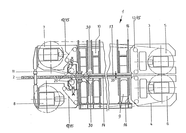
According to Figure 1, the continuously-operating press 1
is composed of the press plate 9, the mobile ram 10 and the
pull straps connecting them. To adjust the press gate 35, the
ram 10 is moved up and down by a series of hydraulic pistons
and cylinders 31 and then locked in the selected setting. The
steel belts 3 and 4 are each guided over a driving pulley 5
` and 6 and guide pulleys 7 and 8, respectively, around the
press plate 9 and the ram 10. To minimize friction between
the heater plates 13 and 14 attached to the press plate 9 and
. the ram 10, on the one hand, and surrounding steel belts 3 and
4, on the other, a roller bar carpet composed of roller bars
12 is provided. The roller bars 12, the axes of which extend
lS perpendicular to the direction of travel of the belts, are
connected thereby in strap chains 15 with the prescribed
dimensions along both sides of press 1, and unroll onto the
`~ heater plates 13 and 14 from the ram 10 and the press plate 9
. on the one hand and onto the steel belts 3 and 4 on the other
hand, and thereby carry the compressed material along, guided
through the press 1.
It is further apparent from Figure 1 that the roller bars
12 in the feed gate 11 next to the feeder gear wheels are `
'j inserted into the horizontal press level to determine the form
and strength.
A suitable preassembly site 32 as illustrated in Figure 6
is required to implement the invention. Instead of a normal ~;
surface load of 6 bar for a machine foundation, a load-bearing
capacity of 1 bar can be expected for a poured surface for`~ 30 example, and a capacity of 2 bar on a natural ground surface
if, as can be seen in Figure 4 and Figure 7, a mineral
concrete layer or fine gravel 23 of about 20 cm, sealed with a
20 cm thick layer of lean concrete 24, in the support area of
the continuously-operating press is first installed in the
foundation layers G.
The construction or conceptual design of the
continuously-operating press for the preassembly and the pre-
3~
2~2217~
- 5 -
start-up is illustrated in Figures 2 to 4, which show in
particular their subdivision into several individual modules
Cn, specifically subdivided according to longitudinal
sections, e.g. an overall press length of about 50 m
subdivided into five individual modules Cl, C2, C3, C4 and C5, ~
with a length of 10 metres and module weights of about 150 to ~ -
250 and with four vertical mechanical interfaces 26. The
longitudinal dimensions of the individual modules Cn are
preferably oriented in accordance with the given space
constraints of transportation within the factory from the ~
preassembly site 32 to the ultimate site in the production ~ -
shed 33; e.g. for transverse entry, the internal widths Sl
between the king posts 34 are determinant for the length D, or
width F of the continuously-operating press; for longitudinal ~ -
entry, this is the individual module Cn through the king post
width S2.
With respect to the already mentioned low surface load-
bearing capacity of the preassembly site 32 (surface pressure
of 1 to 2 bar) and the sufficient rigidity characteristics
(resistance to flexion and torsion) for the transport of the
individual modules Cn, they are affixed to two large surface
assembly bridges 17, which in turn are connected to each other
by several transverse braces 20 to take the lateral shearing
forces. These assembly and transportation bridges 17 perform
three functions, specifically as mounting bases for
preassembly on the level 32 of the foundation layers G, as a
transport bridge for the individual modules Cn and as a base
in the foundation of the production shed 33.
Advantageous versions of the individual module Cn consist
of~
a) Detachable flange connections 27 between the individual
modules Cn, e.g. between individual module Cl and
individual module C2, to absorb the horizontal tractive
and compressive force during production.
b) Roller surfaces and support design, e.g. heater plates 13
and 14 with roller plates 18 are calculated for
horizontal telescoping, so that the front interfaces 26
: 2~22174
-- 6
- of the two individual modules Cl/C2 in the connected
operating state brace each other to absorb the vertically
active hydraulic forces on multipot 36 or the vertical
supporting forces on transverse stud 16 together against
these construction elements 16 and/or 36.
c) The roller bar carpet, held together on the outer ends by
means of a guide chain system, is connected by a
detachable end pin coupling above and below the vertical
separating level between Cl and C2.
d) After completion of the pre-start-up, the steel belts 3
and 4 are dismantled. For security during
transportation, the steel belts are replaced by spacers
or plates 37 (preferably made of wood) inserted into the
press area between the upper and lower roll bars 12, so -
that the upper roller carpet, in particular, remains
fixed in lts seat.
e) By means of lateral support straps 21, which are hooked
laterally at equal intervals onto the long sides of the ;
individual module Cn, preferably in such as way as to be
detachable, the module units, connected individually or
as a complete group along the mechanical disconnecting ~ ~ -
points 26 by means of hydraulic elements 22 can be lifted
at the preassembly site 32 onto heavy-duty carriers
(e.g. air cushion vehicles) or trucks 29 and lowered into
the prepared foundation 38 in the production shed 33.
The horizontal bridge carrier elements 39 stressed by
flex and the transverse studs 16 in the ram and press plate
area to support the heater plates 13 and 14 are telescoped
horizontally in such a way that the vertical transver~e studs
16 (king posts) on the press plate and the ram 10 absorb the
vertical compressive forces which appear under the stress of
operation in the static correctly calibrated arrangement.
The roller plates 18, which are attached to the heater
plates 13 and 14 as protection against wear for the roll bars
12 which roll off them during operation, are also telescoped
into each other at the mechanical connecting points 26 in the
course of the horizontal telescoping of the individual module
212217'1
Cn, so that the meshing of the saw-toothed transition area
(see Flgure 3) ensures a continuous rolling during subsequent
~ load operation.
: On the brldge carrier elements 39 of the individual
modules Cn, wedged assemblies 40 with a high shear load-
bearing capacity are provided on the vertical interfaces or
~; connecting points 26 (which are located between the press
cylinders arranged outward in the known manner). The wedged
assemblies telescope together and produce an automatic
connection between the individual modules Cn which are heavily
stressed during operation. .
As an alternative to the described foundation layers G, -
reusable steel plates or flat pontoons can be laid upon the
levelled poured surface, which may also be mechanically
compacted, to take the assembly bridges 17.
Figure 5 illustrates an individual module Cn in section,
which shows recesses 41 in the assembly and transport bridges
17 which are used to permit passage of the lifting elements
22.
` 20 In accordance with the invention, a continuously-
i operating press as shown in Figure 1 composed of individual --
modules C1 to C5 as illustrated in Figures 2, 3, 4 and 5, is -~
preassembled and tested on the preassembly site 32 (Figure 6).
If the obtained measurements are satisfactory, the press to be
- 25 replaced 42 can be dismantled and removed from the production
,~ shed 33. At the same time, the steel belts are removed from
the continuously-operating press 1 at the preassembly site 32 ~- ;
and the press 1 is separated at the interfaces 26 into the ~ ~ :
individual modules C1, C2, C3. C4 and C5. The transportation
of the individual modules Cn from the preassembly site 32 to
' the production shed 33 can now begin. The lifting elements 22
; (see Figure 7 and Figure 8) are now used to raise the
individual modules Cn in the prescribed order, place them on a
truck 29 and drive them into the production shed 33. Here
lifting jacks can raise them to the right position on the
foundation 38 and reassemble them as a continuously-operating
press 1. If no suitable trucks and/or lifting jacks are
:
~ 212217~
-- 8
available, the individual modules Cn can also be raised by the
lifting elements 22 and transported on rails 28 into the
production shed 33, as shown in Figures 7, 9, 10, 11 and 12. ~ :
Telescoping rails 38 make it possible to drive over the
: 5 foundation 38. After the lifting mechanism has been lowered
. and the telescoping rails have been retracted, the individual
:~ modules Cn can be set down on the foundation rails 44 and -~
rolled or pushed to their proper position. Once all the ~ :
individual modules C1 to C5 have been driven in, the
' 10 continuously-operating press 1 can be reassembled and put into
operation. ;~ ~:
- ~