Note: Descriptions are shown in the official language in which they were submitted.
W O 94/07043 2 1 2 2 2 5 8 P~T/US93/08781
PAD TYPE HYDRODYNAMIC THRUST BEARINGS
HAVING A MODU1AR CONSTRUCTION
Backqround of the Invention
The present invention relates to hydrodynamic
bearings. In such bearings, a rotating object such as a
shaft is supported by a stationary bearing pad via a
pressurized fluid such as oil, air or water. Hydrody-
namic bearings take advantage of the fact that when the
lo rotating object moves, it does not slide along the top of
the fluid. Instead the fluid in contact with the rotat-
ing object adheres tightly to the rotating object, and
motion is accompanied by slip or shear between the fluid
particles through the entire height of the fluid film.
Thus, if the rotating object and the contacting layer of
fluid move at a velocity which is known, the velocity at
intermediate heights of the fluid thic~ness decreases at
a known rate until the fluid in contact with the station- -
ary bearing pad adheres to the bearing pad and is motion-
less. When, by virtue of the load resulting from its
support of the rotating object, the bearing pad is
deflected at a small angle to the rotating member, the
fluid will be drawn into the wedge-shaped opening, and
sufficient pressure w~ e generated in the fluid film
to support the load. This fact is utilized in thrust
bearings for hydraulic turbines and propeller shafts of
ships as well as in the conventional hydrodynamic journal
bearing.
Both thrust bearings and radial or journal
bearings normally are characterized by shaft supporting
pads spaced about an axis. The axis about which the pads
are spaced generally corresponds to the longitudinal axis
of the shaft to be supported for both thrust and journal
bearings. This axis may be termed the major axis.
To a large extent, the problems associated with
prior art hydrodynamic be2rings have been solved by the
bearing construction described in U.S. Patent No.
4,676,668 to Ide, the present inventor. This bearing
WO 94/()7()43 2 1 2 2 2 ~ ~ PCl /IJS93/t)f;7Xl
construction includes a plurality of discrete bearing
pads press fit into a support portion. I'he bearing pads
may be spaced from the support member by at least one leg
which provides flexibility in three directions. To pro-
vide flexibility in the plane of motion, the legs areangled inward to form a conical shape with the apex of
the cone or point of intersection in f ront of the pad
surface. Each leg has a section modulus that is rela-
tively small in the direction of desired motion to permit
compensation for misalignments. These teachings are
applicable to both journal and thrust bearingls.
While the construction described in the present
inventor's previous patent represents a significant
advance in the art, commercial production has shown that
improvements are possible. For instance, the shape of
the bearing pads is relatively complex; and consequently
somewhat difficult to mass produce, use in radial or
journal bearings, and dampen.
Additionally, since the bearing pads are uni-
tary, the entire bearing pad must sometimes be con-
structed out of the most expensive material necessary in
any part of the bearing. The ~nitary construction also
makes it difficult to change the performance characteris-
tics of any partîcul~ bearing pad. This necessitates a
different bearing pad for each application thus limiting
the ability to standardi~e bearing components (i.e., use
standard compQnents in different configurations for each
application) and achieve the cost and other commercial
advantages associated with standardization.
The press fitt.ing of the pads into the carrier
also complicates assembly of bearings. Moreover, by vir-
tue of this press fit, the bearing pads cannot be easily
removed from the carrier. This complicates reuse of the
carrier (the most substantial portion of the bearing) in
the event of a failure~
W~ 94/0704~ 2 1 2 2 2 S 8 PCl`/US~3/~X7Xl
summary of the Invention
The present invention relatPs to improvements
in hydrodynamic thrust bearings of the type which
includes a plurality of discrete bearing pads mounted in
a carrier in a circumferentially spaced relation. Gener-
ally, the present invention relates to improvements in
pad and carrier design.
Conceptually, the bearing pads and carriers of
the present invention are designed by treating the pads
and carriers as a solid piece of material and then selec-
tively removing or adding material to the solidl to cause
it to deflect in a desîred way under design loalds. It
can be readily appreciated that myriad designs are possi-
ble. Thus, it should be kept in mind that the structural
features disclosed herein are generally applicable to any
other bearing pad if structural conditions make this
possible.
The inventor has discovered that in many spe-
cific applications such as in high speed applications, it
is necessary to examine and evaluate the dynamic flexi-
bility of the entire system consisting of the shaft or
rotor, the hydrodynamic lubricating film and the bearing.
This analysis should also involve consideration of other
conditions which coul~ impact wedge ~ormation. For
instance r it is know that shaft to pad contact can lead
to ~hermal crowning which will, naturally, impact the
shape of the space ~etween the pad and the shaft surface.
In computer analysis of this system using a finite ele-
ment model, it has been determined that it is necessary
to treat the entire bearing as a completely flexible
member that changes shape un~er operating loads. By
adding more or less flexibility via machining of the
basic structure, bearing characteristics may be achieved
that provide stable low friction operation over wide
operating rangss. A number of variables have been found
to substantially affect the bearing's performance charac-
teristics. Among the most important variables are the
shape, size, location and material characteristics (e.g.
W094/07(~ 1222- 9 PCT/OS~3/0~7XI
modulus of elasticity etc.) of the pad and support mem-
bers defined by the bores, slits or cuts and grooves
formed in the bearing. The shape of the support members
has been found to be particularly important.
In accordance with another important aspect of
the bearings of the present invention, the bearing pads
can be supported for deflection so as to retain the
hydrodynamic fluid, thus obviating the problem of fluid
leakage. With respect to radial or journal bearings, the
support structure is designed such that, under load, the
bearing pad deflects to form a fluid retaining pocket.
Generally, such a support is achieved when the primary
support portion is connected to the bearing pad proximate
the axial edges of the bearing pad and the center of the
lS bearing pad is not directly supported, i.e., is free to
deflect radially outward. With respect to thrust bear-
ings, the pad is supported so as to tilt toward the bear-
ing' s inner diameter under load so as to prevent centrif-
ugal leakage. Generally, this i~ achieved when the pad
support surface at which the primary support structure
supports the bearing pad is located closer to the bearing
outer diameter than to the bearing inner diameter. When
the primary support structure includes two or more radi-
ally spaced beams, th-~ overall support structure must be
designed ~o cause deflection of the bearing pad at the
inner end. Further, when the bearing pad is supported by
a plurality of radially spaced beams and the region
between the beams is not directly supported, the pad will
tend to deflect so as to form a concave fluid retaining
channel.
The pad surface bearing pad portion may also be
coated with a separate material such as hardened rubber
or the surface may have a separate pad insert of a high
performance material such as silicon carbide.
The support portion preferably has a shape
which conforms to the shape of the openings in the car-
rier. If this shape is non-cylindrical, the pad will be
precisely positioned when it is fit into the carrier.
W094~07()43 PCT/US93/OX7XI
2122258
-- 5 --
A wear surace may be molded onto the pad when
the pad support is such that wear is expected during
operation, e.g. at start-up. The wear surface is prefer-
ably formed from a material having a high PV limit such
as CELEDYNE~. If necessary, a layer of surface roughness
can be provided on the pad to better secure the wear
surface to the pad. The edges of the pad may be tapered
to improve inlet bending.
In some instances, the requirements for a par-
ticular application may be satisfied with a simple centerpost design which although quite rigid is shaped or posi-
tioned to favorably influence deflection. The center
post may bs double curved, cylindrical, ov~l or any other
easily manufactured shape. The post may be offset with
respect to the pad portion it supports.
Brief Description of the Drawinqs
FIG. lA is a side cross-section of a thrust
bearing construction ac~ording to the present invention.
F~G. lB is a partial top view of the bearing
construction of FIG.lA.
FIG. 2 is a perspective view of a sector shaped
thrust pad with arrows indicating the side lines for the
top side and edge vie~s.
FIG. 3 is a perspective view of a circular
thrust pad.
FIG. 4 is a side view of a thrust pad with
tapered edges.
FIG. 5 is a top view showiny an arrangement of
bearing pads on a carrier according to the present inven-
tion.
FIG. 5A is a top view of another bearing pad
according to the present invention.
FIG. 6A is a top view of a carrier member hav-
ing a locator posts for positioning the bearing pads.
FIG. 6B is a cross-section of the carrier mem-
ber of FIG. 6B along the lines indicated in FIG. 6A.
w094~07043 2 ~ 2 2 2 5 9 PCT/US~3/~1~7~1
FIG. 6C is a top view of the carrier member of
FIG 6D.
FIG. 6D i~ a cross-section of another carrier
member having a locating protrusion.
5FIG. 6E is a top view of a carrier member hav-
ing locating openings formed therein.
FIG. 6F is a cross-section of the carrier of
Fig. 6E.
FIG. 6G is a top view of a carrier formed with
non-cylindrical openings.
FIG. 7 is a top view of another bear.ing pad
: according to the present invention.
FIG. 7A is a cross-section of the beiaring pad
of Fig. ~ along the lines indicated by arrows in Fig. 7.
15FIG. 7B is a front view of the bearing pad of
Fig. 7.
FIG. 7C is a cross-section of the bearing pad
of Fig. ~ formed with a wear surface.
FIG. 8 is a partial front view of a bearing
assembly showing one bearing pad and a part of a carrier
in section.
FIG. 8A is a top view of the bearing pad of
Fig. 8 with some obscured features in phantom.
FIG. 8B is a front vi1ew of the bearing pad of
~5 Fig. 8 having a surface roughening layer formed thereon.
FIG~ ~C is a front view, partially in section,
of the bearing pad of Fig. 8 with a wear surface formed
thereon.
FIG. 9 is a top view of another bearing pad
according to the present invention.
FIG. 9A is a front view of the bearing pad of
Fig. 9.
FIG. lO is a top view of another bearing pad
according to the present invention.
35FIG. lOA is a f ront view of the bearing pad of
FIG. lO.
FIG. lOB is a front view of another bearing pad
according to the present invention.
W091/07(W3 2 12 2 2 5 ~ PC1/US93/OX7~1
FIG. ll is a front view of anather ~earing pad
according to the present invention.
FIG. 12A is a front view of another bearing pad
according to the present invention.
FIG. 12B is a front view of another bearing pad
according to the present invention.
Det iled DescriPtion of the Drawings
FIGS. lA and lB illustrate the general environ-
ment of the present invention, namely hydrodynamic thrust
bearings, which include a carrier member lO having a
plurality of openings such as bores formed therein and a
plurality of bearing pad members 20 mounted in the open-
ings. The bearing pads may be ~ircumferentially spaced
as indicated in, for example FIGS lB.
In the pastl the pad shap of hydrodynamic
bearings has been primarily dictated by manufacturing
convenience. For a thrust bearing, this has tradition-
ally meant sector shaped pads to maximize the area of
?0 suppor~ or -- in`the case of applicant's prior U.S. Pat-
ent No. 4,676,6~8 -- circular pads for low cost manufac-
ture. In many cases, such conventional. pad shapes can be
supported to obtain optimum results. However, the pres-
ent inventor has discovered that important performance
characterlstics can be achieved by modifying conventional
pad shapes. Conseguently, the support structure can be
simplified, and in some cases, even eliminated.
Examples of typical thrust pad shapes are
illustrated in FIGS. 2 and 3. FIG. 2 shows a sector
shaped pad 132. The sight lines for a top view T, an
edge view E and a side view S are indicated by arrows
labeled T, E and S, respectively. FIG. 3 shows a circu-
`lar pad 20. These pad shapes are characterized by unin-
terrupted planar surfaces and a uniform pad thickness.
The arrangement of the pads on the carriers is illus-
trated in ~igs. 5 and 5A.
~ arious modifications to traditional thrust pad
shapes will be discussed hereinafter. In general, the
W094/07043 ~ 2 5 ~ 8 - ~/VS~3/~)~7XI
effect of these modifications for any particular applica-
tion can be determined through the use of finite element
analysis. Such an analysis can also account for other
factors which might impact wedge formation. For
instance, if the support structure pe~mits sustained
shaft to pad contact, the pad will heat up. This temper-
ature rise will result in thermal distortions or crowning
of the pad. With finite ele~ent analysis these thermal
effects can be used to enhance wedge formation. It
should be kept in mind that any of these modifications to
the shape of the pad may be used in combination or alone.
Also, the modi~ications can be easily adapted to pads
having shapes other than the specific pad shapes illus-
trated. Moreover, the pads may be symmetrically shaped
to allow bidirectional operation or non-symmetrical to
provide different operating conditions depending on the
direction of rotation.
FIG. 4 illustrates another possible modifica-
tion to the basic pad shape. Specifically, it has been
learnad that tapering the leading edge of the bearing pad
results in increased inlet ~ending. This allows more
lubricant to enter into the shaft-pad space which
increases the load carrying capability of the pad. Com-
plex finite element analysis using computers can predict
the amount of bending needed to obtain optimum lubricant
~low.
The drawings illustrate the u~e of tapered
edges in thrust, radial, and combined radial/thrust bear-
ings. Specifically, FIG. 4 is a side view along the S
30 axis in FIG. 3 illustrating a thrust bearing pad 132 with
a taper 132t formed at each edge~ Again, the taper is
provided at each end to allow for bidirectional opera-
tion. ~ course, if unidirectional operation is suffi-
cient, only one edge, the leading edge, should be
tapered~
Figs. 7-7C illustrate a pad construction
according to the present invention. In this construc-
tion, a pad includes a sector shaped pad 23 supported on
W~94/07043 PCT/US~3/087X~
2 l2~2~8
a support post 70. As best shown in Fig. 7, the support
post 70 has an oval cross-section a radial dimension
which is larger than its circumferential dimension. Pro-
vision of an elongated post 70 of the type shown in Figs.
7-7C serves several functions. First, when a pad 20 of
this type is mounted in a carrier lQ of the type shown in
Fig. ~G ~discussed below) having complimentary openings
101 for receiving the post 70, the pad 20 is automatic-
ally positioned in the precise location desired. In con-
trast, if tha pad 20 were formed with a cylindrical sup-
port, it would have to be positioned in some other way.
- In addition, the provision of an alongated oval
post of ~he type shown in Figs. 7-7C affects t]he support
of the pad portion ~3. Specifically, since the support
post 70 has a radial dimension greater than its circum-
ferential dimension, the support of the pad 23 is more
rigid in the radial direction than in the circu~ferential
dimension. In the bearing pad 20 shown in Figs. 7-7C
this effect is compounded since the sector shape of the
pad portion 23 has a circumferential dimension greater
than its radial dimension. Thus, as a result of both the
shape of the pad portion 23 and the configuration of the
support post 7~, the circumferential ends of the pad por~
tion 23 are relatively unsupported whereas the central
region of the pad portion 23 is relatively rigidly sup-
ported.
An important aspect in the design of bearing
pads such as those shown herein is to allow lubricant to
circumferentially enter the pad region and to prevent
circumferential leakage of the fluid lubricant. In the
case of the bearing pads shown in Fig. 7-7C, this objec-
tive is achieved by designing the support such that under
load, the radially inner edga (RIE) of the bearing pads
deflect downward as viewed in Fig. 7B and the out~r edg~
deflects upward. As best shown in Fig. 7, the support
post 70 is connected to the pad portion 23 at a location
which is closer to the radially outer edge (ROE) of the
bearing pad than it is to the inner edge (RIE) of the
W094/07043 2 1 ~ 2 2 5 9 PCT/US93/0~7Xl
-- 10 --
bearing pad 20. Thus, the pad support surface, i.e~, the
surface at which post 70 contacts pad portion 23, is
located radially outward of the radial dividing line.
Considered another way, the geometric center of the pad
PC is offset from the geometric center of the support
post SC. Hence, the bearing is designed such that under
load, the inner edge of the bearing defle ts downward.
In operation, the downward deflection of the
inner edge of the bearing pad corresponds to deflection
away from the shaft supported and upward deflection of
the outer edge of the bearing pad corresponds to deflec-
tion toward th~ shaft~ The deflected orientation of the
bearing pad permits lubricant to pass the radially inner
edge RIE and enter the wedge region as a result of cen-
trifugal forces and si~nificantly inhibits the loss offluid past the radially outer edge ROE which otherwise
occurs as a result of the centrifugal orces acting on
the fluid. While it is possible to optimize the design
in this regard for any particular application, a general
rule of thumb is that the geometric center of the support
posts SC should be offset from the geometric center of
the pad PC by about 10 percent.
As can be appreciated best from Fig. 7A, the
support post 70 which supports the pad portion 23 is
quite rigid. Indeed, this pad by itself would not permit
movement of the pad portion 23 with six degrees of free-
dom, The pre~ent inventor has found that movement with
six degrees of freedom is not always necessary to achieve
adequate results. For example, in conventional tilt
bearings, the individual pads need only tilt or pivot
about an axis parallel to the rotor. A known rocker
pivot pad has nearly zero rotational pivot stiffness.
Such bearings are known to provide adequate performance,
but t`hey are more expensive and difficult to tailor to
35 - individual applications. Thus, for some applications, a
pad having limited flexibility such aæ that shown in
Figs. 7 and 7C is acceptable.
WO~4/07043 2 1 2 2 2 5 8 PCT/US93/~X7XI
The pad shape can be modified along the lines
discussed above to achieve the disclosed results. In the
case of the bearing pad 20 shown in Fig. 7-7C, one par-
ticular modification employed is the tapering of the
lower circumferential edges of the bearing pads to yield
increased inlet bending. This allows more lubricant to
enter into the shaft-pad space which increases the load
carrying ~apability of the pad as discussed above in
connection with Fig. 4O Specifically, as best shown in
Fig. 7B the lower edge of the pad portion 23 is tapered~
Since the particular bearing pad 20 shown is intended for
bidirectional operation, (i.e., it is symmetrical and can
support a shaft rotation at either direction~, each of
the two radially extending circumferential edges, (i.e.,
those edges extending between the radially inner edge
tRIE) and the radially outer edge (ROE)) of the pad por-
tion 23 are provided with tapers 23t to increase inlet
bending. ~s best shown in Figs. 7 and 7~, the bearing
pad further includes a chamfer on its top surface to
permit easy entrance of lubricant.
As noted earlier, the pad construction shown in
Figs. 7-7C has limited flexibility. In many cases, this
flexibility, though limited, is ~sufficient to achieve
hydrodynamic operation. In other instances, the carrier
10 in which the pad 20 is mounted can be provided with
flexibility to allow increased deflection if this is
called for. In some cases, however, the relatively rigid
support structure is adequate in all cases except during
start up. In these instances, the present invention
allows for the possible provision of a wear surface so as
to avoid damage to the pad during start-up as shown in
the embodiment of Fig. 7C. The objective of such a wear
surface is to allow the pad to withstand wear caused
during start-up. Even with a relatively rigid support
structure of the type shown in Figs~ 7-7C, the pad can be
designed to achieve hydrodynamic operation during steady
state conditions, but the wear characteristics at start-
up can cause a potential concern. By providing a wear
W094/07043 2 1 2 2 2 5 9 PCT/US93/OX781
- 12 ~
surface the bearing is in effect designed to operate in
two modes. First, at initial start-up, t~e beariny acts
as a wear bearing wherein the shaft rubs against the pad
surface. After start-up, the bearing pad operates hydro-
dynamically and there is little or no contact between theshaft and bearing pad surface.
While various materials can be used to provide
the wear surface the preferred embodiment of the present
invention comprises the use of a CELEDYNE~ resin molded
around the pad as shown at 25 in Fig. 7C.
The bearing pad 20 may be formed of a wide
variety of metal or plastic materials. In most common
applications, however, the bearing is formed of metal
typically either cast bronze or steel. Depending on the
lS surface roughness of the pad 20, it may be desirable to
add a layer of surface roughnes 24 before molding the
CELEDYNE~ wear surface 25 onto the pad 20. Several meth-
ods for doing this are described bel~w.
Another bearing pad according to the present
invention is disclosed in Figs. 8-8C. In this embodi-
ment, the bearing ~ad 20 includes a circular pad portion
23 which is formed with a continuous taper 23t along its
lower circumferential edge. The pad portion 23 is sup-
ported by a cylindrical support post 71 which, in this 25 case, coaxially supports the pad portion 23. The pad 20
further includes a base 7~ supporting the support post
71. In this particular case, the base 73 provides no
additional flexibility to the bearing pad and functions
merely to support the support post 71. Thus, if desired,
the support post 7l could be mounted directly in a car-
rier and the base 73 could be eliminated without affect-
ing the function of the pad 20.
Alternatively, the base 73 could be formed with
a threaded opening for receiving a fastening screw 41 to
secure the pad 20 to a carrier lO a~ shown in Fig. 8.
This type of fastening screw securement means could be
used to secure most of the pads 20 disclosed herein to
W094/~7~)43 PCT/U~93/08781
2 1 ~ 8
the carriers lo disclosed herein, but is particularly
well suited to pads having a solid base.
The pad shown in Figs. 8-8C is symmetrical.
Thus, its position within a bore 101 in a carrier 20 does
not affect its performance. Hence, there is no need for
means for precisely positioning the pad within the bore~
The pad shown in Figs. 8-8C is, again, quite
rigid. The support post 71 rigidly supports the central
region of the pad portion 23, but does not directly sup-
port the outer periphery of the pad portion 23. Accord-
ingly, the leading edge of the bearing pad por~ion 23 is
less rigidly supported and likely to bend to permit for-
mation of a hydrodynamic wedge. The inlet bending effec
is further enhanced by the provision of the taper 23t
which as described herein, improves wedge formation.
Because of the relative rigidity o~ the support
post 71 which supports the pad portion 23, there is a
possibility that wear will occur between the pad surface
and the shaft in certain applications. In these applica-
tions, if such wear is particularly troublesome, thebearing pad 20 can be provided with a wear surface 25 as
shown in Fig . 8C and previous l y discussed. Again, the
wear surface 25 can be formed of any suitable wear mate-
rial. However, the currently preferred materîal is CELE-
DYNE~ resin molded onto the surface of the pad portion23.
Since the surface of the pad portion 23 is
t~pically quite smooth, it is so~etimes difficult to
cause a wear material such as CELEDYNE~ to adhere to the
pad surface. A currently preferred method of adhering a
resin material such as CELEDYNE~ to a bearing pad in
accordance with the present invention will be described
hereinafter with referen~e to Figæ. 8B and 8C.
To obtain proper adherence it is necessary to
have a sufficiently rough surface onto which the resin i5
molded. This surface can be achieved by casting the part
as a relatively rough surface. In the case of machined
part, however, it is preferable to provide a layer of
W094/07~43 PCT/US93/11~7~1
21~2259
- 14 -
surface roughness 24 prior to molding the resin onto the
pad. There are a number of ways in which this can be
achieved. For example, small pieces of bronze can be
melted onto the pad surface to form a rough surface. The
preferred method, however, is to flame spray the pad with
an aluminum/bronze (lO% aluminum/90% bronze)alloy. By
doing this, a relatively porus/rough surface can be
achieved. This surface, during molding, allows the resin
to flow into the surface crater~ and to lock into place.
The pads are then heated slightly ~efore they are
inserted into the mold cavity, allowed to continue to
heat in the mold, and then resin is injected onto the
pad. The parts may then be annealed if desired, Tests
have shown that the bonded surface shows good to excel-
lent flow of material into the coating and adequate bond
- strength.
Fig. 8B shows a pad 20 having a surface rough-
ening layer 24 provided there~n. Again, this surface
roughened layer 24 is preferably formed by flame spraying
an aluminum/bronze alloy onto the pad surface.
Fig . 8C shows a pad 20 in which the layer of
resin 25 has been molded onto the pad 20 and is adhered
to the pad by the surface roughening layer 24.
As previously noted, the support post 7l shown
in Figs. 8 and ~A supports pad portion 23 at the qeomet-
ric center of the pad portion 23. The advantage of such
an arrangement is that the pad is symmetrical. This
simplifies manufacture and assembly somewhat. In other
instances, however, it is preferable to have the support
post offset with respect to the pad portion 23. Figs. 9-
lOB depict bearing pads in which the support post 71 is
offset to achieve the desired results.
In the embodiment shown in Figs. 9 and 9A, the
support post 7l has a support center SC which i5 radially
offset from the center PC of the pad portion 23 by an
amount indicated as R0. Note, however, that the support
is symmetrical about the circumferential center line CCL
which is defined as a radial line passing through the
W09~/07(~43 ~ 1 2 2 2 5 8 PCT/US93/087~1
center of the pad portion 23 and the axis of the carrier
l0 (not shown). The radial center line indicated as RCL
in Fig. 9 is defined as the circle center on the axis of
the carrier and passing through the pad center PC.
There are several considerations involved with
a non-symmetrical pad of the type shown in Figs. 9 and
9A. The first such consideration is that the pad 20 must
be precisely positioned within the opening l0l in the
carrier l0 because of its non-symmetrical construction.
Various ways of achieving this are discussed herein,
including use of locator posts and the like. In the
embodiment shown in Figs. 9 and gA, a locator post ~02 is
provided on the base 73. As discussed in regard to Figs.
6E and 6F, the carrier l0 is provided with a complimen-
tary opening 103 for receiving the locator posts 102 so
as to precisely position the bearing 20 in the carrier
10 .
Because the support center SC of the supportpost 7l is located radially past the radial center line
RCL/ the pad portion 23 is supported such that the radi-
ally innermost edge RIE is supported for downward deflec-
tion under loading so as to increase bending to allow
centrifugal entrance of oil. Conversely, the radially
outermost edge ROE of the pad portion 23 is rigidly sup-
~5 ported so that it forms a fluid dam to prevent centrifu-
gal leakage of oil~ Again, as a rule of thumb the point
of attachment of the support post 7l to the pad portion
23 is normally shifted about l0 percent toward the outer
diameter to increase bending.
The pad portion 23 is also provided with a
continuous taper 23t to increase inlet bending as dis-
cussad above.
Finally, it i8 noted that the pad shown in Fig.
9 and 9A is suited for bidirectional operation since the
pad is symmetrical about the circumferential centerline.
In other words, the deflection characteristics of the pad
will not change when rotation of the shaft is reversed.
W0~4/07(~ PCT/US93/~X7~1
- 16 -
2 12~59
Figs. 10-lOB show another non-symmetrical pad
construction. In this case, however, the pad 20 is
designed for one-directional or unidirectional operation
in the direction indicated by the axrows on the radial
center line RCL. In the case of such one directional
bearings, the point of attachment of the support post 71
to the pad portion 23 is typically offset~ As a rule of
thumb, the pad portion 23 should be shifted about 12%
toward the trailing edge as shown best in Fig. 10. Thus,
the support post has a support center SC which is offset
from the center PC of the pad portion 23 circumferen-
tially by a circumferential offset amount indicated as CO
in Fig. 10 and radially by an amount indicated as RO in
Fig. 10.
The radial offset serves essentially the same
function as the radial offset in the bidirectional bear-
ing shown in Figs. g-9A and described above. The ircum-
ferential offset CO is provided to improve inlet bending
by making the leading edge less rigidly supported. The
pad portion 23 also includes a continuous taper 23t to
improve inlet bending. Again, like the embodiment of
Figs. 9 and 9A, the embodiment of Figs. 10-lOB includes a
locator post 102 to allow the pad 20 to be precisely
positioned within the carrier 10.
2S Fig. lOB shows a slight modification to the
bearing pad of Figs~ 10 and lOA. Specifically , the pad
20 is provided with a wear surface 25. Again, the wear
surface is preferably provided by molding a CELEDYNE~
resin onto the pad portion 23. In the embodimellt shown
in Fig. lOB, the support post 71 is also significantly
thinner, and hence, more flexible than the support posts
71 shown in Figs. 10 and lOA.
It should be noted that, support posts
described herein can have thin, thick or moderate diam-
eters depending on viscosity, load, speed, envelope andgeneral operating requirements. In addition, the operat-
ing requirements can be modelled using finite element
W09~0704~ 2 ~ 2 2 2 ~ 8 PCT/US9~/OX7XI
17 -
analysis to determine the optimum dimensions for any
particular application.
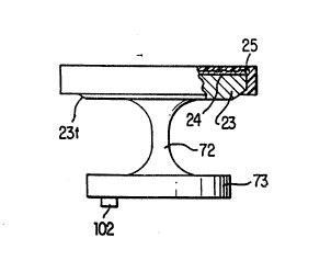
Fig. 11 shows another pad 20 according to the
present invention. The pad 20 includes a pad portion 23,
a support portion 7~ and a base 73. Again, the base 73
is designed to be mounted in a bore lOl in one of the
carrier constructions 10 disclosed herein. In this case,
the base 73 is formed with a thread ~0 as discussed above
in connection with Figs. llA and llB, for example. The
support 72 of the pad in this case is formed wi.th a con- -
tinuously curved surfa~e which is thinnest at the central
portion of the support 72 and flares out toward~ both the
pad portion 23 and the base 73. Geometrically, this
complex shape is roughly equivalent to the shape of the
hole in a doughnut or, more technically, the shape
enclosed within a torus or annulus which is a clouble-
curved surface generated by revolving a circle about a
straight line axis which does not contain the center of
the circle. The purpose of the complex shape of the
support portion 72 is to increase flexibility of the
center region of the support post 72 and relieving stress
from the end regions at which the post 72 joins the pad
portion 23 and the base 73. These regions might other-
wise be subject to stress concentrations. By virtue of
this construction, the pad 20 has a tendency to tilt more
eacily about the center of the support portion 72 to
improve deflection. The support portion 72 may be coax-
ial with the pad portion 23, to simplify manufa~ture and
assembly. Alternatively, the support portion may be off-
set either radially or both radially and circumferen-
tially to achieve the aforementioned functional advan-
tages.
Figs. 12A-12B disclose another bearing pad
according to the present invention~ This bearing pad
construction is similar to that shown in Fig. ll and
described above. Specifically, the bearing pad 20
includes a pad portion 23, a base portion 73 and a sup-
port portion 72. The support portion 72 again flares in
WO 94~07~43 PCf /VS93/OX7XI
~12~25~ - 18 -
a continuous curve toward both the pad portion 23 and the
base 73. In this case, however, the center region of the
support portion 72 is somewhat elongated such that the
shape of the support 72 cannot, strictly speaking, be
described as the shape defined as the void left in the
center region of a torus. Nonetheless, the support por-
tion 72 achieves the same effects of providing maximum
flexibility in the center region of the support 72 and
relieving stress and reducing flexibility at those por-
tions of the support 72 nearest the pad portion 23 andthe base 73.
The pad portion 23 is provided with a continu-
ous annular taper 23t at the lower edge thereof. As
noted earlier, the provision of such a taper improves
inlet bending.
Further, the base 73 includes a locator projec-
tion 102 for precisely posîtioning the pad 20 with the
bores 101 of a carrier. Of course, such a locator post
is especially useful when the post center is offset from
the pad center.
As shown in Fig. 12B, the bearing pad 20 may be
provided with a wear surface 25. Again, the wear surface
25 is preferably formed by moldling CELEDYNE~ to the pad
portion 23 as shown in Fig~ 12B. In addition, if neces-
sary to assure proper adherence, a surface rougheninglayer 24 may be provided on the surface of the pad por-
tion 23 prior to molding of the resin or other material
onto the pad portion 23.
One particularly important aspect of the pres-
ent invention is the disclosure of easily machinable padshapes. Specifically, the circular pad shapes of the
type disclosed in Figs. 8-12B can be readily formed from
cylindrical bar stock using a lathe. Pad shapes which
can be formed using a lathe provide a significant advan-
tage over ~nown constructions in which complex machiningor casting must be performed both in terms of production
cost and the cost and complexity of manufacturing proto-
types. In regard to the offset constructions, it is
W09~/~7043 2 ~ ~ ~ 2 ~ 8 PCT/US93/087Xl
- 19 -
noted that the pad would have to be lathed on more than
axis to form such configurations.
Another important advantage of the present
invention is the disclosure of bearing pads which are
formed separately from the carrier. Such constructions
make it possible to use standard carriers lO to achieve a
wide variety of results using a relatively limited number
of pads. Although the base portions of a number of the
pads shown herein are described as simple cylindrical
bases which can be mounted in the bores, it should be
understood that the base can be threaded, press fit,
adhered with an adhesive or the like to the carrier.
FIGS. 6A, 6B, 6C, 6D, 6E, 6F and 6G illustrate
another aspect of the present invention whereby the bear-
ing pads 20 can be precisely located within the carrier1~. In FIGS. 6A and 6B, the carrier 10 is provided with
locating pins 102 non-symmetrically disposed within the
bores lO1 provided for receiving the bearing pads 20.
The locator pin 102 can be received in one of the non-
symmetrically disposed openings in a bearing pad supportstructure (or a similar opening provided somewhere else
in the bearing pad), to precisely position the bearing
pad within the bore in the carrier lO. An alternative
construction is illustrated in FIGS. 6C and 6D. In this
construction locating protrusions 102 extending from the
wall of the bore lOl and used instead of sPparate locat-
ing pins. The locatiny protrusion can be received in a
complementary notch formed in the dog leg or tertiary
support portion of any of the bearing pads of the present
invention. By virtue of this locking pin or protrusion
arrangement, the pre-biased bearing pads are forced into
proper alignment when mounted in the bore.
Figs. 6E-6F illustrate a similar construction
in which locator holes 103 are formed in each of the
bores 101. The locator holes 103 are adapted to receive
the locator pins 102 formed on bearing pads such as, for
example, those shown in Figs. 9A and lOA. Since bearing
pads formed with a locator pin 102 can only be positioned
W094/07~14~ 2 1 2 2 2 ~ ~ PCT/US93/(~X7Xl
- 20 -
within the bore 101 such that the locator pin 102 is
received in the locator hole 103, the pads must be pre-
cisely positioned if they are to be received in the open-
ings 101. One advantage of the construction shown in
Figs. 6E-6F is that the carrier 10 will receive pads
which do not have a locator pin 102 just as it will
receive pins that do have a locator pin 102. Thus, the
carrier construction shown in Figs. 6E-6F can be more
widely used.
Yet another form of carrier for precisely posi-
tioning the bearing pads within the carrier is shown in
Fig~ 6G. This carrier 10 is adapted for receiving pads
having a oval base such as the pads shown in Figs. ~-7C.
Thus, the openings 101 have a non-circular, in this case,
oval shape. By virtue of the non-circular shape of the
openings 101, the pads must be precisely positioned to
fit in the opening.