Note: Descriptions are shown in the official language in which they were submitted.
~2~U~5
PROC~SSING APPARA~
This invention relates to the processing of
photosensitive material such as photo~raphic film, x-
ray, or paper~
~'~
Manufacturers of photographic processing
equipment are continually striving to attain rapid and
accurate processing of photographic materials. This
equipment should be easily manufactured, reliable and
economical. This involves simplifying the design
and/or reducing the physical size of various elements
in the processorO
In typical prior art processors, a sheet of
photosensitive material is passed through a series oE
open top cha~bers, each containing a quantity of a
processing fluid, by a series of rollers generally
centered so that the photosensitive material will pass
into and out of each open top cha~ber. There are a
number of disadvantages with respect to processors of
this type. First, the lengthy transport path impedes
the ability to realize high processing throughput.
Exposing of the photosensitive material to atmospheric
conditions between the processing chamber is generally
not conducive to processing due to the lack of
photochemical interaction that takes place during this
exposure. Bxposure to air can also enhance the
breakdown of the processing chemistry. In addition,
~he photosensitive material is more susceptible to
scratching or marring due to the stresses induced as
the material remains in substantial contact with
multiple sets of rollers required to transverse a
serpentine transport path.
Another problem with prior art processors is
that each processor is typically designed to be used
21223~.i
--2--
with a particular type chemistry and/or film. This
results in a lack of common parts between processors
due to the dlfferent requirements required of each
processor. Therefore, it is necessary for manufactures
and~or distributors to stock a large variety of
different parts in order to manufacture and repair
various different type processors. Further, designing,
redesigning, retrofitting or updating of processors can
be quite time consuming and costly. Additionally, due
to lack of commonalty, changing production lines from
one type processor can require substantial amounts of
time and money.
While some attempts have been made to
standardize components in certain processors, such as
illustrated in US-A-4,989,028; US-A-4,994,840; US-A-
5,059,997; and US-A-5,093,678, these devices are
limited in their ability to be interchangeable and
modified for different applications.
Applicants have invented an improved
processor which is simple in construction, easy to
repair and retrofitted, allows for shorter design time
and manufacture change over, and which can be easily
modified to operate in a variety of configurations and
allow interchange ability between various processors
such that common subassemblies can be used in a variety
of different type processors.
In accordance with one aspect of the present
invention there is provided a processor for processing
a photosensitive material. The processor having a
housing chamber. At least one modular wall structure
is provided for dividing the housing chamber into a
plurality of ~luid processing chambers. A modular
processing device may placed in at least one of the
plurality of fluid processing chambers for circulating
212~05
.
a processing fluid placed in said Eluid processing
chamber.
Other objects and advantages will become
apparent from the following description presented in
connection with the accompanied drawings wherein:
Figure 1 is a cross-sectional view of a
processor made in accordance with the present invention
containing a plurality of modular subassemblies;
Figure 2 is a top plan view of the processor
of Figure 1 with modular subassemblies removed;
Figure 3 is a perspective of one of the
modular wall section used in the processor of Figure 1;
Figure 4 is partial enlarged perspective view
of one of the processing modular sections illustrated
in Figure 1;
Figures 5A and SB are enlarged fragmentary exploded
perspective views of a portion of the processor of
Figure 3 illustrating the end portions of a pair of
modular wall sections and adjacent modular pump~
sections:
Figures 6A and 6B are enlarged ~ragmentary exploded
perspective views of the ol:her end portions of the
modular wall sections and adjacent modular pump
sections of Figure 5; and
Figure 7 is a cross-sectional view of the
modular wall section and adjacent pump section as taken
along line 6-6 of Figure 6.
~_~ ' .
In the description that follows use is made
of the terms "upper", "lower", "top", "bottom", etc. to
facilitate discussion of the present invention. This
terminology is used only to provide perspective with
respect of the accompanying drawings and is not
intended to confine ~he scope of the present invention
described therein.
21~23~3
--4--
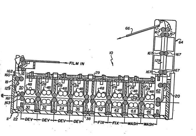
Referring to Figures 1-3 of the clrawings
there is shown a processor 10 having a housing 11 which
comprises a pair of side walls 14,16, a pair of end
walls 18,20 and a bottom wall 22 which form a fluid
tight housing chamber 26. In the particular embodiment
illustrated, walls 14,16,18,20 and 22 each comprise
individual components that are secured together by any
desired means, for example by threaded fasteners.
However the housing 11 may be fabricated as a single
component or as many components as desired. The
processor 10 further includes a plurality of modular
wall structures 28 which divide the housing chamber 26
into a plurality of fluid processing chambers
30,32,34,36,38,~0,42,44,46. Each of the fluid
processing chambers 30-46 are capable of holding an
appropriate processing fluid. In the particular
embodiment illustrated, four fluid processing chamhers
30,32,34,36 combine to form the development section of
the process which are designed to hold developing
processing fluid. In the particular embodiment
illustrated, there is illustrated a multistage
developing processing system wherein the active
component of the processing fluid decreases as the film
passes through the processor. However, it is to be
understood that any desired number of development
processiny chambers may comprise the developing
section. Applicants have found the use of multistage
development processing chambers enhances the chemical
utilization efficiency of overall processing of the
photosensitive material.
Fluid processing chambers 40,42 define the
fix section of the processor and contain processing
fluid typically used ~o fix the photosensitive
material. Here, as in the development stage, a co-
current multistage process is utilized, however, it is
2~2230~
to be understood that any desired number of fixingprocessing chambers may be pxovided in the processor.
In the preferred embodiment illustrated, an
intermediate processing chamber 38 is provided between
the fluid processing chambers containing the
development proce~sing fluid and the fixing sol~tion.
It is important that no fixing solution contaminate the
developing processing solution. Even very small
amounts of fixing solution can severely affect the
efficiency of the de~elopment solution. Intermediate
wall assembly 29 is provided for separating fluid
processing chambers 36,40 is provided. Modular wall
assembly 29 hasically comprises a pair of roller wall
sections of the modular wall structures 28 which are
secured together to form a sealed air chamber 38
therebetween. Preferably as illustrated the chamber 38
is slightly pressurized with air. In particular the
embodiment illustrated the chamber 38 is pressurize
with about two inches of water pressure. Applicant
have found that ~his small amount of pressure to be
sufficient to minimize any leakage from chambers 36,38.
Additional intermediate wall asseI~lies 29 may ~e
utilized at various locations as desired or be entirely
omitted.
Processing chambers 44,46 define the wash
section of the processor 10 wherein the photosensitive
material is washed. In the particular embodiment
illustrated, wash water flows from chamber 46 in~o
chamber 44, thus providing a counter current Elow for
the wash water.
Disposed in each of the development
processing chambers 30,32,34,36 there is provided a
modular processing module 48 for circ~ulating a
processing fluid within the chamber against the
photosensitive material passing therethrough. In the
preferred embodiment illustrated, modules 48 are
` ` 2122305
-6-
provided in each of the fluid processing chambers
30,32,34,36. It is, of course, to be understood that
modular processing modules 48 need not be provided in
each Eluid processing chamber. Similar-like processing
modules are also provided in chambers 40,42,44,46 for
circulating of the respective processing fluid therein
against the photosensitive material passing
therethrough.
The processor 10 further includes an entrance
chamber 50 wherein a photosensitive material is
delivered to the first processing chamber 30 and a exit
chamber 62 adjacent the last processing chamber 46 for
receiving the photosensitive material. A drying module
64 is provided adjacent the exit chamber Eor receiving
a photosensitive material and drying the photosensitive
material therein and transporting the photosensitive
material onto a receiving tray 66.
The modular wall structures 28 are slideably
mounted within housing 12. For the sake of clarity,
only one of the modular wall structures 28 will be
discussed in detail, it being understood that the other
wall structures 28 are similarly constructed.
Referring to Figure 3, the modular wall structure 28
comprises a support frame 110 having a top and bottom
~5 support 112,114, respectively, and a pair of side walls
116,118 which ar~ secured together to the top and
bottom supports 112,114 to form a substantially rigid
structure. In the particular embodiment illustrated,
top and bottom supports 112,114 and side walls 116,118
are secured together by thread fasteners. However,
various other means may be used for securing these
parts together. The support frame 110 is preferably
made of a light-weight thermo plastic material. In the
particular embodiment illustrated, support frame 110 is
made of a standard ABS material (Acrylonitrile-
Butadiene-Styrene polymer)O The wall structure 28
212230~
--7--
further includes an upper wall member 120 mounted to
lower surface 113 of top support 112 and a lower wa].l
support member 122 mounted to the upper surface 115 of
bottom support 114. The ends 117 of each wall member
120,122 are fastened to the interior side of side walls
116,118, by any desired means to ;provide seal surfaces
at their respective interfaces. Additionally, wall
members 120,122 are each tapered at their lower and
upper ends 121,123, respectively, to form wiping
surface 124,126 in opening 125 therebetween. Modular
wall assembly 29 is similar in construction to wall
structure 28 except that a pair of roller wall sections
120,122 are secured to top, bottom and side walls of
frame 110.
As best illustrated by reference to figures 1
and 2, the housing 11 is provided with a plurality of
generally U-shaped channels 127 which extends
continuously along side walls 14,16 and bottom wall 22
in a direction substantially perpendicular to the path
129 of travel of the film going through the process~r.
Each channel 127 being designed to receive a modular
wall structure 28 or 29.
Positioned in the opening provided between
wiping surfaces 124,126, as best seen by reference to
figure 3, there is provided a pair of substantially
parallel contacting rollers 128,130. The rollers
128,130 are designed to rotate in such a manner so as
to drive a photosensitive material between the rollers
124,126 and through the apparatus. Referring to Figure
5, rollers 128,130 are driven by a drive train assembly
140 which includes a pair of gears 142 which are
connected to shafts 144,145 in rollers 128,130. Drive
train 140 further includes a drive shaft 147 rotatably
mounted to frame 110. A pair of drive gears 149 are
secured to the lower end of shaft 147 which engage
gears 142. A take-off drive gear 146 is provided at
` 212230;3
the upper end of drive shaft 147. The gears 142 are
secured to the end of rollers 124,126 such that wh~n
shaft 144 is rotated, it will cause the rollers 128,130
to rotate in the desired direction. A primary drive
shaft 150 (see Figure 2) is provided at the upward end
of wall 14. A plurality of gears 151 are provided
along shaft 156 for engaging and driving gears 146.
Modular wall structure 28 is desi~ned so that take-off
gear 146 slideably engages its associated gear 151 as
modular wall structure is set into the processor. Any
appropriate drive means may be connected to sha~t 150.
In the particular embodiment illustrated, a motor (not
shown) having a shaft 193 i.s connected to shaft 150 by
drive belt 157 and pulleys 161, 163. Utilization of
vertical shaft 147 for transferring power to the
rollers submersed in the processing fluid has the
additional advantage of adding very little agitation to
the processing fluid. This minimizes exposure of the
processing chemicals to air, thereby avoiding
undesirable oxidation and reducing the life of the
processing chemicals.
One of the side walls 116,118, for example,
side wall 116, of the frame 110 is provided with a
vertically extended projection 154 (see Figure 5A)
which is designed to slide and mate within a
corresponding vertically extending recess 153 provided
in the side walls of channel 127. This indexes the
modular wall structure 28 with the drive train on
housing 11.
The frame 110 is provided with means for
providing a sealing relationship with housing 11. In
particular, frame 110 is provided a substantially U-
shaped recess 155 which extends continuously along side
walls 116,118 and bottom support 112 (see figures 5 and
6). Recess 155 is designed to receive an elastomeric
gasket 158 having a subst~ntially circular cross-
2122~0.7
sectional configuration. The gasket 158 is made of amaterial and sized such that it will form a sealing
relationship with the adjacent side of the channel 127
in which side walls are designed to be placed. In the
particular embodiment illustrated, gasket 158 is made
of silicone rubber having a 40 durometer shore A
hardness. A suitable silicone rubber ( ASTM D1418) may
purchased from Apple Rubber Products, Inc. of
Lancaster, New York. Installation of the modular wall
structure 28 is accomplished by simply sliding the wall
structure 28 down into the housing 11. The sealing
relationship wall structure forms with housing 11
divides the housing into separate fluid processing
chambers. The side walls 116,118 are each slightly
tapered such that the upper end is slightly longer than
the lower end adjacent the bottom wall so that a small
compressive force is applied between the gasket 150 and
the adjacent side wall of the channel 127 in which the
structure 28 is placed. If and when repair is
nece~sary to either the modular wall structure 28
and/or modular processing module 48, they can simply be
removed and replaced by another identical structure.
In the preferred embodiment illustrated, the
modular processing modules 48 are identical in design
and construction. Therefore, a discussion of only a
single modular processing module 48 will be described
in detail, it being understood that the other
processing modules 48 are likewise constructed.
However, it is to be understood that the processing
modules 48 placed in the processing chambers need not
all be of the same type or of the same construction.
The modules 48 need only have a construction such that
it can easily slide in and out of it respective
chamber.
Referring to figures 4, 5 and 6, modular
processing module forms a channel or recess 170 for
- 2122'~0i
-10-
receiving of the photosensitive material. In the
particular embodiment illustrated, the modular
processing modul~ 48 is designed to circulate
processing fluid such that the processing fluid will be
impinged against the photosensitive material as it
passes through the recess 170. Module 48 includes a
frame 166 having a top member 169 and a pair of side
walls 172, 173. An upper section 171 and lower section
173 are secured to frame 166 which forms the recess 170
for receiving the photosensitive material. Upper and
lower sections 171,173 each having a chamber 177
wherein a pair of gears 179 are provided. The rotation
of gears 179 cause fluid to enter chamber 177 as
indicated by the arrows, and pass through exit 181 to
recess 170 and impinge against the photosensitive
material. Side walls 172,173 are designed to be
received in a pair of oppositely disposed channels
174,175 provided in side walls 14,16 of housing 11.
The channels 17~,175 are aligned such that the modular
processing module 48 extends substantially ~ransversely
across the housing chamber. One of the side walls
172,173 of frame 168 is provided with a indexing
projection 176 which is designed to mate and slide into
a vertically extending recess 178 provided in the
adjacent side wall of channel 174 which thereby allows
the modular processing module 48 to be properly indexed
within the housing chamber 26. As shown in Figure 6,
the opposite side wall 173 of each of the modules 48 is
received in channel 174 in the opposite side walls 16
of housing 12~ Thus, each processing module 48 is
removably supported and aligned in an operative
position in its associated processing chamber.
Means are provided for aligning the recess
170 of module 48 with the nip of roller 126,128 of the
adjacent wall sections 128. In the particular
embodiment illustrated, the bottom of side walls 172
~122'~0~
are provided with an indexing block 179 which mates
with the surface 115 of bottom wall of the adjacent
sect.ions 28. The side wall 173 is similar aligned wikh
the other end of modular wall section 28. As
illustrated in Figure 7, the side wall 172,173 extend
adjacent the walls 116,118 of the adjacent wall
sections 28. This assists in providing further
stability to the modular pump sections 48.
Means are also provided in the processing
module 48 for circulating of the processing fluid
against the photosensitive material. There is provided
means for transferring power to the module 48. In
particular, a gear train 180 is provided for
transferring power to the module 48. In particular,
the gear train includes a rotatably shaft 182 connected
to a take-off gear 184 at one end of the shaft 182 and
a pair of transfer gears 186 which mesh with
corresponding drive gears 188 in module 48. The drive
gears 188 are connected to pump gears 179. The take-
off gear 184 meshes with a corresponding drive gear 189secured to primary drive shaft 191 rotatably mounted to
the top of side wall 16 (see Figure 2). Modular
processing module 48 is designed such that drive gear
189 slideably engages take-off gear 184 as module 48 is
inserted into its associated chamber. Drive shaft 191
i5 driven by any drive means desired. In the
particular embodiment illustrated, drive shaft 191 is
driven by motor (not shown) having a drive shaft 193
which is connected to shaft 191 by a connecting drive
belt 195 and pulleys 197, 139.
Due to the modular construction of the module
wall structures 28, intermediate wall assembly 29 and
modular processing modules 48, processors of various
types and construction can be made simply and easily by
simply rearranging the modules within the housing, or
simply providing a new housing designed to meet the
` 212230~
particular needs of that type processor. For e~ample,
in the particular embodiment illustrated, four
development processing chambers are shown. However, if
50 desired, a fewer or greater n~mber of processing
chambers may be provided by simply providing a housing
haviny suEficient number of channels to receive the
processing module 48 and wall structure 28. Li]sewise,
the desired number of fixing or washing processing
chambers may be made to be greater or equal than the
preferred embodiment illustrated. This allows a great
versatility in the designer in adapting the processor
to various chemistries or films that are to be
processed in the processor without substantially
changing individual component parts, thus requiring a
minimal amount of redesigning or fabrication.
Likewise, the processor can be easily modified to
incorporate modified and/or improved wall structures
and/or processing modules without any substantial
redesign to the processor. Additionally, time can be
saved in changing production lines from producing one
type processor to another type.
The processor of the embodiment illustrated
provides a simple apparatus which allows the film to - -
travel in a substantially straight path through the
processor. A brief discussion of the operation of the
processor follows. Referring to Figure 1, the film
enters into chamber 50 and passes through initial pair
of rollers 160,162 and then through a second pair of
rollers 161,163 into the first modular processing
chamber 30 and fluid processing pump 48.
Photosensitive material then passes through the rollers
in the modular wall structure 28 which are driven by an
appropriate source so as to further cause the
photosensitive material to travel along the film path
129 illustrated. The photosensitive material continues
through each successive fluid processing chamber
~12230~
-13-
through the exit chamber 62 and into the dryer 64 by a
series of rollers 167 whereupon the photosensitive
material is dispensed onto chute 66 at the exit of the
dryer.
S It is, of course, understood that various
other means may be provided for providing of the
appropriate driving force through each of the wall
structures and processing modules as desired.