Note: Descriptions are shown in the official language in which they were submitted.
2122383
24-NF-05317 j ~:
...., ~ .
PI~GER MILL ~7DREL MEASURING DEVICE
Field of the Invention
This invention generally relates to electro-optical
methods for detecting and measuring the shape or contour
of objects. In particular, the invention relates to a
system for precisely measuring the contour of tapered
cylindrical objec~s, such as a mandrel used in a pilger
mill for cold rolling of tubing.
Backaround of the Invention
Pilger mills are used for cold rolling of seamless
pipes or tubing to desired dimensions and tolerances.
The pilgering process is advantageously used, for
example, to produce Zircaloy tubing for nuclear fuel
bundle assemblies. The pilgering process consists of
stepwise feeding and turning a tube between a set of
tapered die rolls reciprocating over a tapered mandrel.
This results in a smooth reduction of the tubing to the
desired tube diameter and wall thickness.
For purposes of illustration, a pilger mill 10 is
shown in FIG. 1 employing a thrust block 12 for
supporting a rod 14 which extends through a feed
carriage 16 to hold a mandrel die 18. In operation, an
ingoing tubing 20 is pushed by the feed carriage 16
through an entry chuc~ 22 and between a pair of spaced
rolls 24 and 26. The rolls 24 and 26 rotate as they
undergo a reciprocating lateral movement as indicated
by the arrow 28. The rolls have respective grooves 30
and 32 formed therein; each of which has a semicircular
cross section with a groove diameter that tapers
smoothly in size along the arc length on the roll
-.~ '
"'' ~ ~:
2122383
-2- 24-NF-05317
circumference from the ingoing tubing diameter to the
desired diameter of the finished tubing 34. As the
ingoing tubing 20 advances through the reciprocating
rolls, the tubing is worked to the desired diameter and
degree of tolerance.
Reciprocating rotary movement is imparted to the
rolls 24 and 26 by pinions mounted on the roll axle
engaged with racks fixed to the machine frame (not
shown3. A crank drive 38 and push rod 40 are used to
drive the rolls mounted on a saddle (not shown) along
the racks. The two grooved rolls embrace the tubing
from above and below as they roll over a predetermined
length of the tubing, called the pass length. At the
completion of each stroke, the entry chuck 22 and exit
chuck 36 grip the tubing and rotate it a predetermined
angular amount such that the entire circumference of the
tubing can be worked in stepwise fashion.
The ingoing tube 20 is elongated to form the
finished tubing 34 through cold rolling reduction of the
tubing diameter and wall thickness between the rolls 24
and 26 and the mandrel 18. The mandrel tapers in the
direction of rolling from the size of the inside
diameter of the ingoing tubing 20 to the size of the
inside diameter of the finished tubing 34. The
condition and dimensions of the mandrel affect the
amount of inner diameter reduction and the output tube
quality. Rey mandrel traits which result in poor
quality output tubing include reverse taper, ovality,
size problems, surface condition and defects.
Prior methods for addressing this problem include
the use of a hand micrometer to measure the outer
diameter of the mandrel at a particular location
determined by eye. However, such manual measurement
does not provide enough information to accurately
determine if the mandrel has acceptable traits for
continued use.
2122383
-3- 24-NF-05317
Summarv of the Invention
The present invention seeks to provide the ability
to precisely measure pilger mill mandrels, and thereby
increase the quality and consistency of tubing produced
through the pilgering process. The invention is a
method and an apparatus for measuring a tapered
cylindrical object, such as a mandrel used in the
pilgering process. The apparatus comprises ~eans for
rotatably supporting a mandrel in a generally horizontal
position on a linear positioning table assembly having
a slide mounting for a laser micrometer, an axial
position stepper motor for moving the laser micrometer
stepwise along the axial length of the mandrel, and an
angular position stepper motor for stepwise rotation of
the mandrel.
At each axial position of the laser micrometer, the
mandrel is rotated in a stepwise manner. At each
angular position of the mandrel, the laser micrometer
measures the mandrel outer diameter, making multiple
scans (e.g., 512 scans). For each angular position at
an axial point along the mandrel, the average outer
diameter is determined for the multiple scans. Taking
the average avoids deviations in the measurement results
due to noise.
The result is a series of outer diameter
measurements at predetermined angular increments over
the circumference of the mandrel which effectively
represent the cross-sectional contour of the mandrel at
that axial position. The contour measurements are then
repeated for a series of axial positions over the length
of the mandrel, thereby effectively representing the
contour of the tapered cylindrical surface.
Thus, the step sequences of an angular position
stepper motor and an axial position stepper motor are
controlled by computer so that the laser micrometer
measurements are taken at precise angular and axial
' . ",,.
. ' ' ~.
21~2383 ~;
~ : .
-4- 24-NF-05317 ;
intervals. A selected number of angular intervals are
circumferentially distributed at equal angular intervals
about the circum~erence of a plurality of cross
sections. Each of the plurality of cross sections is
taken at each respective axial positions arranged at
intervals along the length of the mandrel to be
measured.
Average outer diameter measurements are computed
by averaging the measurements taken at each position.
The mandrel is then assessed by computer program
functions for comparing selected traits of the measured
mandrel for deviation within given error levels, such
as for incremental change in outer diameter, ovality,
and fitting to a reference mandrel profile. If the
measured traits are found to be within specified ranges
of tolerances, the mandrel can be designated as
acceptable for use.
Brief Descri~tion of the Drawinqs
~he preferred embodiment of the invention will be
described in detail with reference to the drawings,
wherein:
FIG. 1 is a schematic diagram of a conventional -~
pilger mill in which tubing is cold worked between a
reciprocating pair of rolls and an inner mandrel;
FIGS. 2 and 3 are top and side views showing a
system in accordance with the present invention for
precisely measuring a tapered cylindrical object such
as a mandrel used in the pilgering process; ~;
FIG. 4 is an end view of a linear positioning table
30 used in the mandrel measuring system of FIG. 2; ~-
FIG. 5 is a sectional view of the linear
positioning table taken along section 5-5 in FIG. 2;
IFIG. 6 is a diagrammatic perspective view
¦illustrating use of the system in accordance with the
invention to measure a mandrel; and
2122~3
.
-5- 24-NF-05317
FIG. 7 is a block diagram of a computer logic
sequence for control of the measuring system in
accordance with the invention.
Detailed Description of the Preferred Embodiment
A preferred embodiment of the invention will be
described in terms of the specific application of
measuring the mandrel for a pilger mill. It is
understood, however, that the principles of the
invention are applicable to related applications for
precisely measuring any tapered cylindrical object.
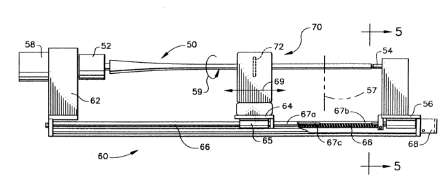
Referring to FIGS. 2 and 3, a system for precisely
measuring a mandrel 50 includes a holder collet 52
rotatably mounted on a fixed member 62 and a holder
spindle 54 mounted to an adjustable, lockable end member
52 at an opposite end from the collet 52. The fixed
member 62 is securely mounted at one end of a linear
positioning table assembly 60. The adjustable member
52 is slidably mounted at the opposite end of linear
positioning table assembly 60. The end position of end
member 56 with spindle 54 may be adjusted to accommodate
a range of mandrel lengths, as indicated by the dashed
line 57 in FIG. 3.
A rotary stepper motor 58 has a rotary drive
coupled to the collet 52 for moving the mandrel held
between the collet 52 and the spindle 54 in stepwise
fashion in an angular direction indicated by the arrow
59
The linear positioning table assembly 60 also
incorporates a slide member 64. The slide member 64 is
. . , : . . ~,
moved linearly in an axial direction (indicated by the
arrow 69) relative to the mandrel 50. The slide member
64 is driven by a screw rod 66 coupled to the rotary
drive output of another rotary stepper motor 68.
For the specific application of pilgering nuclear
fuel rod tubing, the linear positioning table assembly
,,
'." , '
. ., ~
2122383
... .
-6- 24-NF-05317
may be selected to accommodate a range of mandrel
length, for example, up to 45 inches. A suitable linear
positioning table assembly is the M1-90000 Series sold
by LinTech Positioning Systems of Monrovia, California.
Overtravel limit switches (not shown) are set at the
ends of the mandrel length to limit the travel of the
laser micrometer 70 along the mandrel S0.
The linear positioning table assembly in accordance
with the preferred embodiment of the invention is
illustrated in greater detail in FIGS. 4 and 5. The
slide member 64 rides on twin rails 67a, 67b through
ball bushings along the travel length (indicated by the
dashed arrow 71) as established by the setting of the ~;
overtravel limit switches. A guide rod 67c is provided
in parallel with and in proximity to the screw rod 66.
Screw rod 66 threads in a threaded member carried on an
underside of the slide member 64. The exact linear
position of the slide member 64 is measured by a scanner
head 82 relative to a gauge plate 80 of a linear encoder
unit. A suitable linear encoder unit is model DRC LX
lB-0042-BA-L10 sold by Motionex, Inc., of Raleigh, North
Carolina. The gauge plate 80 is mounted on a fixed
machine surface parallel to the travel axis and has
optically readable markings thereon which are read by
1 25 scanner head 82 mounted on slide member 64.
¦ A laser micrometer instrument 70 is securely i~
mounted on the slide member 64 of linear positioning
table assembly 60. When the slide member 64 is moved
linearly in an axial direction (indicated by the arrow
69) relative to the mandrel S0, laser measurements of
the outer diameter can be taken at a multitude of axial
positions arranged at intervals along the length of the
mandrel.
As shown in FIGS. 2 and 6, the laser micrometer 70
is preferably of the type having a laser scanning head
72 which emits a sequence of laser beams in a vertical
2122383
-7- 24-NF-05317
curtain 74 which scans across the vertical cross-
sectional diameter of the mandrel at a constant scanning
speed. A photoreceptor unit 76 is disposed opposite to
the scanning head 72, the scanning head and photo-
receptor unit being separated by a scanning gap.
As the beam traverses the diameter of the mandrel
over a predetermined scanning interval, a timer circuit
coupled to the photoreceptor unit 76 measures the
precise time at which the laser beam is first blocked
by the bottommost edge of the mandrel and the precise
time at which the laser beam is detected upon being no
longer blocked by the topmost edge of the mandrel. The
interval between these two instants of time represents
the time required for the scanning beam to traverse a
distance equal to the outer diameter of the mandrel at
the particular axial position of the scanning beam.
Thus, the measurement of the beginning and end times
effectively takes a "snapshot" of the silhouette of the
mandrel at a particular angular position of the mandrel
and at a particular axial position along its length.
The mandrel outer diameter can be calculated by
multiplying the measured time interval by the speed of
scanning. A number (N) of measurements may be taken and
averaged for greater reliability. A suitable laser
m~crometer system for performing such measurements
includes a model LS3060 scan head and a model LS3100
control module sold by Keyence Corp., of Fairlawn, New
Jersey.
At each axial position of the laser micrometer, the
mandrel is rotated in stepwise fashion. At each angular
position of the mandrel, the laser micrometer measures
the mandrel outer diameter. The result is a series of
outer diameter measurements (ODJ~) at predetermined
angular increments (9~) over the circumference of the
mandrel. This data effectively represents the cross-
sectional contour of the mandrel at that axial position.
2122383
-8- 24-NF-05317
The contour measurements are then repeated for a series
of axial positions (X~) distributed at intervals along
the length of the mandrel, thereby effectively
representing the contour of the tapered cylindrical
surface.
FIG. 7 illustrates a computer logic sequence for
control of the measuring system in accordance with the
preferred embodiment of the invention. The step
sequences of the angular position stepper motor 58 and
the axial position stepper motor 68 are controlled by
computer so that the laser micrometer measurements are
taken multiple times (N) at precise angular (Hj) and
axial intervals (X~). They are in effect "geared"
together under program control. A selected number (C)
of angular (~j) intervals are circumferentially
distributed at equal angular intervals about the
circumference (2~) for the cross section at each
respective axial position along the length of the
mandrel. The number (M) of axial intervals (X~) are
spaced at intervals along the length L of the mandrel
to be measured. The number of measurements N and
intervals C, M are selected depending upon the size of
the mandrel being measured and the accuracy required.
Each mandrel is assigned a serial number and the mandrel
profile determined from the laser measurements is saved
in computer memory.
Average outer diameter measurements (ODJ~) are
computed by averaging the N measurements taken at each
position. The mandrel is then assessed by computer
program functions for comparing selected traits of the
measured mandrel for deviation within given error levels
(C1~ e2, ~3), such as for incremental change in outer
diameter, ovality, and fitting to a reference mandrel
profile. IP the measured traits are found to be within
specified ranges of tolerances, the mandrel can be
designated as acceptable for use.
2~22383
,
-9- 24-NF-05317
The measuring system of the present invention
allows rapid, automatic, and complete measurement and
evaluation of the surface profile of the object being
measured. For the application to mandrels for forming
S nuclear fuel cladding, the invention makes it possible
to obtain increased throughput and higher yields for
Zircaloy tubing production. It also results in an
increased likelihood that mandrels will run properly,
and will require less operator adjustments when
installed in the pilger mill. Therefore, less downtime
will be incurred by having to change or reposition a
mandrel. Also, tube quality problems arising from
defective mandrels should be minimized due to the pre-
measurement and precise analysis of the condition of the
mandrels.
These and other variations and modifications of the
disclosed preferred embodiment will be readily apparent
to practitioners skilled in the art of electro-optical
detection and measurement. All such variations and
modifications are intended to be encompassed by the
claims set forth hereinafter.
` ` '~ '' '' ~ ~ . ',
' ~, ' '' ' ::
'''' '-'~''',''`~
~'.:' ''' ''.''
' ' ~;"'~' ~''
.
,.,
,
; ~