Language selection

Search

Patent 2122391 Summary

Third-party information liability

Some of the information on this Web page has been provided by external sources. The Government of Canada is not responsible for the accuracy, reliability or currency of the information supplied by external sources. Users wishing to rely upon this information should consult directly with the source of the information. Content provided by external sources is not subject to official languages, privacy and accessibility requirements.

Claims and Abstract availability

Any discrepancies in the text and image of the Claims and Abstract are due to differing posting times. Text of the Claims and Abstract are posted:

  • At the time the application is open to public inspection;
  • At the time of issue of the patent (grant).
(12) Patent: (11) CA 2122391
(54) English Title: APPLIANCE MOUNTING SYSTEM
(54) French Title: SYSTEME DE MONTAGE D'APPAREILS
Status: Deemed expired
Bibliographic Data
(51) International Patent Classification (IPC):
  • F24F 13/00 (2006.01)
  • F24F 13/32 (2006.01)
(72) Inventors :
  • ANOSZKO, THOMAS J. (United States of America)
(73) Owners :
  • RESEARCH PRODUCTS CORPORATION (United States of America)
(71) Applicants :
  • RESEARCH PRODUCTS CORPORATION (United States of America)
(74) Agent: BORDEN LADNER GERVAIS LLP
(74) Associate agent:
(45) Issued: 1998-01-20
(22) Filed Date: 1994-04-28
(41) Open to Public Inspection: 1994-10-29
Examination requested: 1994-10-31
Availability of licence: N/A
(25) Language of filing: English

Patent Cooperation Treaty (PCT): No

(30) Application Priority Data:
Application No. Country/Territory Date
055,229 United States of America 1993-04-28

Abstracts

English Abstract


A mounting system for suspending an appliance from a
supporting structure includes an elongated U-shaped bracket and a
plurality of fasteners for securing the bracket to a supporting
structure. A mounting pin is disposed toward one end of the
bracket and a mounting hook is disposed toward one end of the
appliance so that the hook may be placed over the mounting pin
and the appliance can be pivotally suspended from the bracket. A
locking means is provided toward one end of the appliance so that
the appliance may be pivoted about the mounting pin and locked
onto the bracket.


French Abstract

Un système de fixation pour accrocher un appareil à une structure support comprend une ferrure allongée en forme de U ainsi que plusieurs attaches pour fixer la ferrure à une structure support. Une tige de fixation est logée près d'une extrémité de la ferrure et un crochet de fixation est logé près d'une extrémité de l'appareil de sorte que le crochet puisse être placé par-dessus la tige de fixation et que l'appareil puisse être accroché de façon pivotante sur la ferrure. Un dispositif de verrouillage est installé près d'une extrémité de l'appareil de sorte que l'appareil puisse être pivoté autour de la tige de fixation et verrouillé à la ferrure.

Claims

Note: Claims are shown in the official language in which they were submitted.


- 4 -

THE EMBODIMENTS OF THE INVENTION IN WHICH AN EXCLUSIVE
PROPERTY OR PRIVILEGE IS CLAIMED ARE DEFINED AS FOLLOWS:


1. A mounting system for suspending an appliance having
a linear dimension from a supporting structure, said system
comprising:
an elongated bracket and means for securing said bracket to
the supporting structure,
a mounting pin disposed toward one end of said bracket and
a mounting hook disposed toward one end of the appliance so that
said hook may be placed over said mounting pin and the appliance
can be pivotally suspended from said bracket, and
locking means disposed toward the other end of the
appliance whereby the appliance may be pivoted about said
mounting pin and locked onto said bracket.
2. The mounting system defined in claim 1 wherein said
elongated bracket comprises a U-shaped channel member with the
legs of the member extending away from the supporting structure.
3. The mounting system defined in claim 2 wherein said
mounting pin comprises a threaded member extending through
openings in said legs of said U-shaped member and across said
channel.
4. The mounting system defined in claim 2 wherein said
locking means comprises a locking sleeve dimensioned to be
disposed within said channel and a locking pin disposed within
said sleeve engageable with said bracket to hold the appliance on
said bracket.
5. The mounting system defined in claim 4 wherein said
locking pin comprises a threaded member extending through said
sleeve and through openings in said legs of said U-shaped member.

- 5 -


6. A mounting system for suspending an appliance having
a linear dimension from a supporting structure, said system
comprising:
an elongated U-shaped channel bracket and means for
securing said bracket to the supporting structure with the legs of
the member extending away from the supporting structure,
a mounting pin disposed toward one end of said bracket and
extending through openings in said legs of said U-shaped member
and across said channel and a mounting hook disposed toward one
end of the appliance so that said hook may be placed over said
mounting pin and the appliance can be pivotally suspended from
said bracket, and
a locking sleeve disposed toward the other end of the
appliance and dimensioned to be disposed within said channel and
a locking pin disposed within said sleeve and engageable with said
bracket whereby the appliance may be pivoted about said mounting
pin and locked onto said bracket.

Description

Note: Descriptions are shown in the official language in which they were submitted.


2~2239~

APPI,I~IC:E ~qOUNTIMG SYSTEM
Bar-k~round of the L.v~lltlon
~he present invention relates to a mounting system for an
appliance and more specifically to a mounting system for
suspending a heat recovery ventilation system from a support
skucture.
Heat recovery ventilation systems are ~pically used in
conjunction with the central heating system of a dwelling and as
such are typically mounted near the ductwork of the furnacc and
more specifically are usually mounted to either the wall or the
ceiling ~oist in that vicinit~. In the past, the installation and/or
mounting of the heat recovery ventilation system was a two man
operation. 1'he unit was typically secured by strapping or bolting
the unit to brackets or the wall or ceiling itself. Since the unit is
rather large and cumbersorne, it was necessaly for one man to lift
and hold the unit in position while the other performed the
fastening steps.
It is an object of the present invention to provide a simple
appliance mounting system that makes it possible for one man to
install and secure a cumbersome appliance ~such as a heat recoveIy
ventilation unit.
of ~h~ Inv~ io~
A mounting system for suspending an appliance from a
supporting structure includes an elongated U-shaped bracket and
means for secunng the bracket to the supporting structure.
In accordance with one aspect of the invention, a mounti~g
pin is disposed toward one end of the bracket and a mounting hook
is disposed toward one end of ~e appliance so that the hook may
be placed over the mounting pin and the appliance can be pivotally
suspended from the bracket.
In accordance with another aspect of the invention, locking
means are disposed toward the other end of the appliance so that

~' i.

2~2%3~1
- 2 -
the appliance be pivoted about the rnounting pin and locked onto
the bracket.
I~e present invention thus provides a simple mounting
system that allows a cumbersome appliance such a heat recovery
ventilation unit to be initially lifted and hung from a bracket and
then swung into a locking position, thus allowing for "one man
installation".
Brlef ]:Pe~s~ tlon of the l:)ra~
The drawings illustrate th~e best mode presently
contemplated of carrying out the invention.
In the drawings:
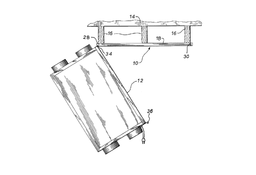
Fig. 1 is a side view of an appliance partially mounted with
the mounting system of the present invention;
Fig. 2 is a side view of an appliance fully mounted using the
system of F'ig. 1;
Fig. 3 is an exploded view of the mounting bracket of the
mounting system of Fig. l;
Fig. 4 is a sectional view along the line 4-4 of Fig. 3; and
Fig. 5 is a sectional view along the line 5-5 of Fig. 3.
DetaL~led Descript~on of tl~e ~ d Embodiment
FIGS. 1-5 illustrate a mounting system 10 for suspending an
appliance 12 from a supporiing structure 14. In this instance,
appliance 12 is a heat recovery ventilation unit and supporting
structure 14 is comprised of a series of ceiling joists 16. While the
drawings illustrate heat recovery ventilation unit 12 being
suspended from an elevated horizontal surface, it should be
appreciated that mounting system 10 can also be utilized with a
vertical mounting surface such as a wall.
As seen in FIG. 3, mounting system 10 includes an
elongated U-shaped bracket 18 haYing legs 20 that define a channel
22. E~racket 18 is secured to ceiling joist 16 by a plurality of
threaded fasteners 24 and legs 2() are proYided with a pair of
aligned openings 26 at one end of bracket 18 that accept a

-~ 2122391
-- 3 -
threaded mounting pin 28. Similarly, legs 20 are prov~ded with
aligned openings 30 at the other end of bracket 18 which accept a
threaded locking pin 32. The r~m:~inin~ elements of mounting
system 10 include a mounting hook 34 disposed at one end of
appliance 12 and dimensioned to fit over locking pin 28 and a
locking sleeve 36 disposed at the other end of appliance 12 and
dimensioned so as to fit within channel 22.
In order to mount appliance 12, an installer first secures
mounting bracket 18 to the supporting structure by means of
fasteners 24. Mounting pin 28 is then inserted through holes 26 in
bracket 18 and secured in place by nut and washer combination 38.
The installer than lifts appli.mce 12 and positions hook 34 over pin
28 so that appliance 12 is pivotally suspended from mounting pin
28 (FIG. 1). The installer then pivots appliance 12 upwardly so that
the opening in sleeve 36 aligns with openings 30 in bracket 18.
Threaded locking pin 32 is then inserted through holes 30 and
sleeve 36 and secured in place by nut and washer combination 40.
The prevent iIlvention thus provides a mounting system that
permits one man to pivotally hang an appliance ~rom the mounting
20 system and then swing the appllance into a locking position and
secure it in that position.

Various modes of carI~ring out the invention are
contemplated as beLng within the scope of the following claims
particularly pointing out and distinctly claiming the subject matter
regarded as the invention.


. . .

Representative Drawing
A single figure which represents the drawing illustrating the invention.
Administrative Status

For a clearer understanding of the status of the application/patent presented on this page, the site Disclaimer , as well as the definitions for Patent , Administrative Status , Maintenance Fee  and Payment History  should be consulted.

Administrative Status

Title Date
Forecasted Issue Date 1998-01-20
(22) Filed 1994-04-28
(41) Open to Public Inspection 1994-10-29
Examination Requested 1994-10-31
(45) Issued 1998-01-20
Deemed Expired 2013-04-29

Abandonment History

There is no abandonment history.

Payment History

Fee Type Anniversary Year Due Date Amount Paid Paid Date
Application Fee $0.00 1994-04-28
Registration of a document - section 124 $0.00 1994-10-07
Maintenance Fee - Application - New Act 2 1996-04-29 $100.00 1996-04-25
Maintenance Fee - Application - New Act 3 1997-04-28 $100.00 1997-03-12
Final Fee $300.00 1997-10-02
Maintenance Fee - Patent - New Act 4 1998-04-28 $100.00 1998-03-17
Maintenance Fee - Patent - New Act 5 1999-04-28 $150.00 1999-04-01
Maintenance Fee - Patent - New Act 6 2000-04-28 $150.00 2000-03-14
Maintenance Fee - Patent - New Act 7 2001-04-30 $350.00 2001-06-04
Maintenance Fee - Patent - New Act 8 2002-04-29 $350.00 2002-06-26
Maintenance Fee - Patent - New Act 9 2003-04-28 $150.00 2003-02-18
Maintenance Fee - Patent - New Act 10 2004-04-28 $450.00 2004-07-16
Maintenance Fee - Patent - New Act 11 2005-04-28 $250.00 2005-03-16
Maintenance Fee - Patent - New Act 12 2006-04-28 $450.00 2006-07-07
Maintenance Fee - Patent - New Act 13 2007-04-30 $250.00 2007-03-16
Maintenance Fee - Patent - New Act 14 2008-04-28 $250.00 2008-03-25
Maintenance Fee - Patent - New Act 15 2009-04-28 $450.00 2009-03-18
Maintenance Fee - Patent - New Act 16 2010-04-28 $450.00 2010-03-17
Maintenance Fee - Patent - New Act 17 2011-04-28 $450.00 2011-03-17
Owners on Record

Note: Records showing the ownership history in alphabetical order.

Current Owners on Record
RESEARCH PRODUCTS CORPORATION
Past Owners on Record
ANOSZKO, THOMAS J.
Past Owners that do not appear in the "Owners on Record" listing will appear in other documentation within the application.
Documents

To view selected files, please enter reCAPTCHA code :


To view images, click a link in the Document Description column. To download the documents, select one or more checkboxes in the first column and then click the "Download Selected in PDF format (Zip Archive)" or the "Download Selected as Single PDF" button.

List of published and non-published patent-specific documents on the CPD .

If you have any difficulty accessing content, you can call the Client Service Centre at 1-866-997-1936 or send them an e-mail at CIPO Client Service Centre.


Document
Description 
Date
(yyyy-mm-dd) 
Number of pages   Size of Image (KB) 
Cover Page 1998-01-28 1 49
Cover Page 1995-04-14 1 80
Abstract 1995-04-14 1 41
Claims 1995-04-14 2 117
Drawings 1995-04-14 2 112
Description 1995-04-14 3 196
Claims 1997-04-22 2 99
Drawings 1997-04-22 2 70
Representative Drawing 1998-01-28 1 14
Fees 1997-03-12 1 69
Fees 1996-04-25 1 50
Correspondence Related to Formalities 1994-04-28 1 26
Correspondence Related to Formalities 1994-04-28 1 21
Examiner Requisition 1997-01-24 2 69
Prosecution Correspondence 1997-02-07 5 281
Office Letter 1995-01-16 1 63
Prosecution Correspondence 1994-10-31 1 30
Prosecution Correspondence 1998-04-28 7 286
Prosecution Correspondence 1997-02-07 2 44
Correspondence Related to Formalities 1996-03-18 1 37