Language selection

Search

Patent 2122392 Summary

Third-party information liability

Some of the information on this Web page has been provided by external sources. The Government of Canada is not responsible for the accuracy, reliability or currency of the information supplied by external sources. Users wishing to rely upon this information should consult directly with the source of the information. Content provided by external sources is not subject to official languages, privacy and accessibility requirements.

Claims and Abstract availability

Any discrepancies in the text and image of the Claims and Abstract are due to differing posting times. Text of the Claims and Abstract are posted:

  • At the time the application is open to public inspection;
  • At the time of issue of the patent (grant).
(12) Patent: (11) CA 2122392
(54) English Title: HEAT EXCHANGER MEDIA FRAME
(54) French Title: CADRE DE MEDIUM ECHANGEUR DE CHALEUR
Status: Deemed expired
Bibliographic Data
(51) International Patent Classification (IPC):
  • F28F 9/26 (2006.01)
  • F28F 9/00 (2006.01)
(72) Inventors :
  • GUETERSLOH, TIMOTHY L. (United States of America)
  • ESSMANN, GARY E. (United States of America)
(73) Owners :
  • RESEARCH PRODUCTS CORPORATION (United States of America)
(71) Applicants :
(74) Agent: BORDEN LADNER GERVAIS LLP
(74) Associate agent:
(45) Issued: 1996-03-26
(22) Filed Date: 1994-04-28
(41) Open to Public Inspection: 1994-10-29
Examination requested: 1994-10-31
Availability of licence: N/A
(25) Language of filing: English

Patent Cooperation Treaty (PCT): No

(30) Application Priority Data:
Application No. Country/Territory Date
055,228 United States of America 1993-04-28

Abstracts

English Abstract


A corner frame construction for a heat exchanger includes
an elongated L-shaped member disposed between the top and
bottom plates of the heat exchanger. The L-shaped member has a
first leg extending parallel to a first edge of the media layers and a
second leg extending perpendicular to the first leg and parallel to a
second edge of the media layers. A first flange is connected to the
first leg and extends inwardly toward the edge of the media layer
and a second flange is connected to the second leg and extends
inwardly toward a second edge of the media layer. A layer of
flowable sealant is disposed along the length of the L-shaped
member and is contact with both the first and second legs, the first
and second media edges and the first and second flange members.


Claims

Note: Claims are shown in the official language in which they were submitted.

-6-

THE EMBODIMENTS OF THE INVENTION IN WHICH AN EXCLUSIVE
PROPERTY OF PRIVILEGE IS CLAIMED ARE DEFINED AS FOLLOWS:


1. A corner frame construction for a heat exchanger of the
type in which a plurality of substantially rectangular media layers
are disposed within a framework having top and bottom plates
joined by four corner members so that the edges of the media
layers are exposed and define two substantially normal air flow
paths, said corner construction comprising:
an elongated L-shaped member having one end connected
to the top plate and the other end connected to the bottom plate,
said L-shaped member having a first leg extending substantially
parallel to a first edge of the media layers and a second leg
perpendicular to said first leg and extending substantially parallel
to a second edge of the media layers,
a first flange member connected to and extending the
length of said first leg, said first flange extending inwardly toward
said first media layer edge,
a second flange member connected to and extending the
length of said second leg, said second flange extending inwardly
toward said second media edge, and
a layer of flowable sealant disposed along the length of said
L-shaped member and in contact with both of said first and second
legs, both of said first and second media edges and both of said first
and second flange members.
2. The corner construction defined in claim 1 further
comprising:
a first lip connected to said first flange member and
extending parallel to said first leg so that said first leg, said first
flange member and said first lip define a sealant containing
channel, and

-7-
a second lip connected to said second flange member and
extending parallel to said second leg so that said second leg, said
second flange member and said second lip define a sealant
containing channel.

Description

Note: Descriptions are shown in the official language in which they were submitted.


2122392

HEAT EXCHANGER MEDIA FRAME
Ra~k~ound of the Illv~ on
The present invention relates to heat exchangers and more
specifically to a corner frame construction for use on a heat
exchanger.
It is known to manufacture a heat exch~nger by stacking a
plurality of substantially rectangular media layers within a
framework so that the open edges of the media layers are exposed
and define two substantially normal air flow paths. The air flowing
along these two flow paths is of different temperatures and heat is
exch~nged between the two.
In order to increase the efficiency of the heat exchanger, it
is desirable that all of the air be forced through the air paths
defined by the media layers and that leakage around the media
layers be kept to a minimum.
In the past, corner constructions for such heat exchangers
were of the type shown in Fig. 2 in which an elongated L-shaped
member was provided at the corner and flowable sealant was
disposed between the L-shaped member and the edges of the
media layers. I~pically, the heat exchanger media is a paper-like
material which will expand and contract as it is exposed to
different temperatures and humidities. This would result in the
edges of the media layer pulling on the sealant and separating it
from the L-shaped member. This would create a leak path for the
air around the media layers and reduce the efficiency of the heat
exchanger.
It is an object of the present invention to provide a corner
construction that enhances the bonding surface for the sealant so as
to prevent media and sealant separation from the corner member.
S tmm~t~ of the I~l-v~ on
An improved corner frame construction for a heat
exchanger of the type in which a plurality of substantially
rectangular heat ~xch~nging media layers are disposed within a

- 2122392
- 2 -

framework having top and bottom plates joined by four corner
members includes an elongated L-shaped member having one end
connected to the top plate and the other end connected to the
bottom plate with a first leg of the L-shaped member extending
substantially parallel to a first edge of the media layers and a second
leg of the L-shaped member being perpendicular to said first leg
and extending substantially parallel to a second edge of the media
layers.
In accordance with one aspect of the invention, the
elongated L-shaped member is provided with a first flange member
that is connected to the first leg and extends the entire length of
the first leg. The flange member extends inwardly toward an edge
of the media layers.
In accordance with another aspect of the invention, a
second flange member is connected to and extends the length of
the second leg of the L-shaped member and extends inwardly
toward a second edge of the media layers.
In accordance with yet another aspect of the invention, a
layer of flowable sealant is disposed along the length of the L-
shaped member and is in contact with both the first and second
legs, the first and second media edges and both of said first and
second flange members.
In accordance with still another aspect of the invention, the
corner construction can be provided with a first lip that is
connected to the first flange member and extends parallel to the
first leg so as to define a sealant containing channel and a second
lip connected to the second flange member and extending parallel
to the second leg so as to define a second sealant con~ining
channel.
3 0 Brief Descrlpffon of the Draw~n~s
The drawings illustrate the best mode presently
contemplated of carrying out the invention.

- 2122392
-- 3 -

In the drawings:
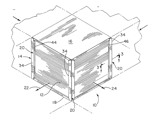
Fig. 1 is a perspective view of a heat exch~nger constructed
according to the present invention;
Fig. 2 is a top cross-sectional view of the corner section of a
prior art heat exchanger;
Fig. 3 is a sectional view along the line 3-3 of Fig. l; and
Fig. 4 is a top cross-sectional view of an alternate
embodiment for the heat ~x~h~nger of Fig. 1.
Detailed Description of the Preferred Embodiment
FIG. 1 illustrates a heat ~xch~nger 10 of the l~rpe in which a
plurality of substantially rectangular heat ex(~h~nging media layers
are disposed within a framework 14 having a top plate 16 and a
bottom plate 18 joined by four corner members 20. The layers of
heat ~xch~n~ing media 12 define two substantially normal air flow
paths 22 and 24. The temperature of the air in flow path 22 is
typically substantially different from that of the air in flow path 24
and since the two flow paths are separated by only a thin layer of
paper-like material, heat is exchanged between the two flowing air
masses.
In the past, the corner construction for a heat exchanger of
this type was such as that shown in FIG. 2. In this corner
construction, an elongated L-shaped member 26 was disposed at
each of the four corners of the framework. A flowable sealant 28
was disposed between L-shaped member 26 and the two edges 30
and 32 of media layers 12. Since the paper-like media layers are
subjected to varying temperatures and humidity levels, it is not
unusual for them to expand and contract. During this expansion
and construction, sealant 28 would be separated from L-shaped
member 26 and an undesirable flow path would be created around
the edges of the heat exchanger media. This would result in
reduced efficiency for heat exchanger 10.

42l22392

The present invention provides an improved corner
construction consisting of an elongated L-shaped member 34
having one end connected to top plate 16 and the other end
connected to bottom plate 18.
L-shaped member 34 is provided with a first leg 36 that
extends substantially parallel to a first edge 38 of media layers 12
and a second leg 40 that is perpendicular to first leg 36 and
extends substantially parallel to a second edge 42 of media layers
12.
A first flange member 44 is integral with first leg 36 and
extends inwardly towards media edge 38. Similarly, second leg 40
is provided with a second flange 46 that extends inwardly toward
media edge 42.
A flowable sealant 48 is disposed along the entire length of
L-shaped member 34 and is in contact with both first and second
legs 36 and 40, first and second media edges 38 and 42 and first
and second flange members 44 and 46. Flange members 44 and 46
provide additional bonding surfaces for sealant 48 so that it is much
more difficult for sealant 48 to separate from L-shaped member 34.
FIG. 4 illustrates an alternate embodiment of the invention
in which a lip 48 is connected to first flange member 44 and
extends parallel to first leg 36 so as to define a sealant containing
~h~nnel 50. Similarly, second flange member 46 is provided with a
lip 52 that extends parallel to second leg 40 and defines a sealant
cont~ining channel 54. This provides yet another bonding surface
and also an obstruction to the movement of the sealant away from L-
shaped member 34.
The present invention thus provides a corner construction
for a heat ~xch~nger in which multiple bonding surfaces are
provided for the sealant so that the expansion and contraction of
the heat exchanger media will not result in the separation of the
sealant from the corner member. This eliminates undesirable

2122392
-- 5 --
leakage flow paths around the comer members and enh~nces the
efficiency of the heat exchanger.

Various modes of carrying out the invention are
contemplated as being within the scope of the following cl~im.s
particularly pointing out and distinctly cl~iming the subject matter
regarded as the invention.

Representative Drawing
A single figure which represents the drawing illustrating the invention.
Administrative Status

For a clearer understanding of the status of the application/patent presented on this page, the site Disclaimer , as well as the definitions for Patent , Administrative Status , Maintenance Fee  and Payment History  should be consulted.

Administrative Status

Title Date
Forecasted Issue Date 1996-03-26
(22) Filed 1994-04-28
(41) Open to Public Inspection 1994-10-29
Examination Requested 1994-10-31
(45) Issued 1996-03-26
Deemed Expired 2013-04-29

Abandonment History

There is no abandonment history.

Payment History

Fee Type Anniversary Year Due Date Amount Paid Paid Date
Application Fee $0.00 1994-04-28
Registration of a document - section 124 $0.00 1994-10-07
Maintenance Fee - Patent - New Act 2 1996-04-29 $100.00 1996-04-25
Maintenance Fee - Patent - New Act 3 1997-04-28 $100.00 1997-03-12
Maintenance Fee - Patent - New Act 4 1998-04-28 $100.00 1998-03-17
Maintenance Fee - Patent - New Act 5 1999-04-28 $150.00 1999-04-01
Maintenance Fee - Patent - New Act 6 2000-04-28 $150.00 2000-03-14
Maintenance Fee - Patent - New Act 7 2001-04-30 $350.00 2001-06-04
Maintenance Fee - Patent - New Act 8 2002-04-29 $350.00 2002-06-26
Maintenance Fee - Patent - New Act 9 2003-04-28 $150.00 2003-02-18
Maintenance Fee - Patent - New Act 10 2004-04-28 $450.00 2004-07-16
Maintenance Fee - Patent - New Act 11 2005-04-28 $250.00 2005-03-16
Maintenance Fee - Patent - New Act 12 2006-04-28 $450.00 2006-07-07
Maintenance Fee - Patent - New Act 13 2007-04-30 $250.00 2007-03-16
Maintenance Fee - Patent - New Act 14 2008-04-28 $250.00 2008-03-25
Maintenance Fee - Patent - New Act 15 2009-04-28 $450.00 2009-03-18
Maintenance Fee - Patent - New Act 16 2010-04-28 $450.00 2010-03-17
Maintenance Fee - Patent - New Act 17 2011-04-28 $450.00 2011-03-17
Owners on Record

Note: Records showing the ownership history in alphabetical order.

Current Owners on Record
RESEARCH PRODUCTS CORPORATION
Past Owners on Record
ESSMANN, GARY E.
GUETERSLOH, TIMOTHY L.
Past Owners that do not appear in the "Owners on Record" listing will appear in other documentation within the application.
Documents

To view selected files, please enter reCAPTCHA code :


To view images, click a link in the Document Description column. To download the documents, select one or more checkboxes in the first column and then click the "Download Selected in PDF format (Zip Archive)" or the "Download Selected as Single PDF" button.

List of published and non-published patent-specific documents on the CPD .

If you have any difficulty accessing content, you can call the Client Service Centre at 1-866-997-1936 or send them an e-mail at CIPO Client Service Centre.


Document
Description 
Date
(yyyy-mm-dd) 
Number of pages   Size of Image (KB) 
Cover Page 1996-03-26 1 16
Claims 1995-04-08 2 73
Drawings 1995-04-08 1 53
Description 1995-04-08 5 251
Abstract 1996-03-26 1 25
Description 1996-03-26 5 209
Claims 1996-03-26 2 53
Drawings 1996-03-26 1 51
Cover Page 1995-04-08 1 33
Abstract 1995-04-08 1 41
Representative Drawing 1999-07-13 1 34
Fees 1997-03-12 1 68
Fees 1996-04-25 1 51
Correspondence Related to Formalities 1996-03-18 1 40
Correspondence Related to Formalities 1996-01-18 1 31
Prosecution Correspondence 1995-05-24 4 253
Prosecution Correspondence 1994-04-28 2 48
Prosecution Correspondence 1994-10-31 1 25
Office Letter 1995-01-11 1 63
Prosecution Correspondence 1995-05-24 1 37
Examiner Requisition 1995-01-24 1 56