Note: Descriptions are shown in the official language in which they were submitted.
21224~
G-11021
PARKING MECHANISM FOR A POWER TRANSMISSION
TECHNI CAI F IELD
This invention relates to power transmission
assemblies having parking mechanisms, and more
particularly, to such assemblies having two parking
pawls engageable with a toothed member on the output
shaft.
10 BACKGROUND OF THE lNV~;N'l'lON
In vehicles Pquipped with automatic
transmissions, the park function is typically
accomplished by locking the drive wheels of the
vehicle through the transmission to ground. The
15 wheels are generally held by engaging a parking pawl ~
into a dedicated parking gear that is connected '
continuously with the wheels through the transmission
output shaft. One such device is shown in U.S. Patent
2,875,856 issued March 3, 1959, to Mrlik et al.
~0 Since the parking pawl prevents the wheels
from turning by grounding them to the transmission
case, the strength requirements of the pawl must
generally be taken by a single tooth design mated to a
gear having complementary teeth formed thereon. This
results in designing the gear with a circular tooth
thickness large enough to withstand the parking
forces. The pawl is also designed with a pressure
angle of approximately 16 degrees to provide for
control of the push out force on the pawl during
~0 parking. This push out force must be maintained with
any range, such that excessive pull out forces are not
' ~ ~
2122461
required when the transmission is parked on a steep
grade.
There have been some consideration given to
multi-tooth park mechanisms, however, these mechanisms
S do not generally provide the resistance to sheer loads
that are desired.
SUMMARY OF THE lNv~NllON
This invention provides a parking pawl
merhAn;s~ of reduced mass and cost and, most
importantly, axial space. The parking function is
accomplished by utilizing the reverse driven gear to
provide the parking gear. The reverse driven gear is
rotationally fast with the transmission output shaft
and, therefore, when grounded, will provide the ~ -
parking function desired.
The reverse gear does have a large diametral
pitch, however, it also has a reduced circular tooth
thickness. To accommodate this reduced circulax tooth
thickness, the present invention provides a parking
pawl which will have two teeth in contact with the
reverse gear during engagement and disengagement.
As a general rule, the working gears of the
transmission have a pressure angle of approximately 22
degrees. The use of this pressure angle on the
parking pawl teeth would result in excess push out
forces resulting in the need for a heavier park
mechAn; ,c~
The present invention solves this dilemma by
rotating the pawl teeth on the parking pawl 6 degrees,
thereby providing an effective and more conventional
2~22461
pressure angle of 16 degrees between the park pawl and
the reverse driven gear
As is well known with park mech~n;~ the
parking pawl must engage during both a forward and a
reverse rotational bias on the output ~haft. To
accommodate this situation, the prP~ent invention
includes a duplicate set of pawl teeth, such that the
first set will provide for the ccntinuous contact if a
forward rotational bias i~ present, and the second set
will provide for continuous rotational contact if a
reverse bias is present.
Since the parking pawl teeth will provide for
continuous contact, the ~ n~l1m circle of the parking
pawl teeth i9 concentric with the a~n~llm circle of
the reverse driven gear when the tip~ of the teeth are
in radial alignment. With this feature, the
ratcheting forces are distributed over all four
parking pawl teeth, thereby reducing the wear which
might otherwise be present on a single tooth, and also
reducing the loads on the tooth when engagement is
attained.
It is therefore an object of this invention to
provide an improved parking mechanism for a automatic
shifting power transmission, wherein the park pawl has
a plurality of teeth, two of which provide constant
contact with a park gear in the transmission during
engagement and disengagement of the parking pawl.
It is another engagement of this invention to
provide an improved parking mechanism for an automatic
transmission, wherein the parking pawl has a plurality
of teeth having an ~d~n~llm circle which i8 concentric
to the ad~ndllm circle of the parking gear immediately
: ~ :
; .. ,. - . , ,.: - : -
-
.~ . . . - .,, ~ :: ,.: .
,
,, ~ . . - , , ~,
. , ~ . ~ ., . ~
2122~61
prior to the teeth on the parking pawl being brought
into mesh with the teeth on the parking gear.
These and other objects and advantage~ of the
present invention will be more readily apparent from
the following specification and drawings.
DESCRIPTION OF THE DRAWINGS
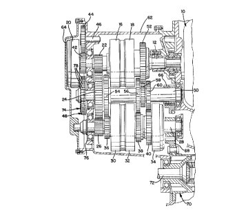
Figure 1 is a cross-sectional elevational view
of a power transmission incorporating the present
invention and taken along the line 1--1 of Figure 2.
Figure 2 is an end view with a portion of the
end cover removed showing the location of the parking
pawl and park gear.
Figure 3 i9 an enlarged view of the parking
pawl during engagement with the park gear at initial
engagement when a forward rotational bias is imposed
on the park gear.
Figure 4 is an enlarged view of the parking
pawl during engagement with the park gear at
approximately 50 percent engagement when a forward
rotational bias is imposed on the park gear.
Figure 5 is an enlarged view of the parking
pawl during engagement with the park gear at full
engagf -nt when a forward rotational bias i9 imposed
on the park gear.
Figure 6 is a view similar to Figure 3,
wherein the park pawl is at initial engagement when a
reverse rotation bias is imposed on the park gear
during the parking maneuver.
Figure 7 is a view similar to Figure 3,
wherein the park pawl is at approximately 50 percent
~ : .: . ~, -
2122461
engagement when a reverse rotation bias is imposed on
the park gear during the parking maneuver.
Figure 8 is a view similar to Figure 3, -~
wherein the park pawl i8 at full engagement when a
reverse rotation bias is imposed on the park gear
during the parking maneuver.
DESCRIPTION OF AN EXEMPhARY EMBODIMENT
In Figure 1, there is seen a power
transmission disposed in cross section. The
powertrain shown therein can be constructed in
accordance with U.S. Patent No. 5,186,065 issued '
February 16, 1993, to Downs. The transmission
includes a torque converter 10, which drives an input
shaft 12 on which is supported a first ratio clutch 16
and a fourth ratio clutch 18. Also drivingly secured ~-
with the input shaft 12 is a reverse clutch 20.
The first ratio clutch 16 is drivingly
connected with a gear 22, which is disposed in meshing
relation with a first ratio output gear 24, which in
turn meshes with a transfer gear 26. The transfer -~
gear 26 is rotatably secured with a countershaft 28 on
which is supported a selectively operable second ratio
clutch 30, a third ratio clutch 32 and fifth ratio
clutch 34. Each clutch 30, 32 and 34 has associated
therewith a respective gear 36, 38 and 40.
The reverse clutch 20 has associated therewith
a reverse gear 42 which meshes with a reverse idler
gear 44 rotatably mounted on a shaft 46. The idler
gear 44 meshes with a reverse driven gear 48 which is
rotatably secured with an output shaft 50.
2 122461
The gear 24 i8 mounted on a conventional one-
way clutch, not shown, on the shaft 50, such that the
first clutch 16 can be maintained in engagement
throughout the forward drive ratios of second through
fifth, if desired. The fourth ratio clutch 18, when
engaged, is operable to connect the gear 52 through
the input shaft 12.
The gear 36 meshes with a second ratio output
gear 54, such that when clutch 30 is engaged, the
drive ratio between the input shaft 12 and output
shaft 50 is determined by the gears 36 and 54. The
gear 38 is driving connected with a third ratio output
gear 56, the gear 52 is meshingly connected with a
fourth ratio output gear 58, and the gear 40 meshes
with a fifth ratio output gear 60.
The reverse gear 48 and the forward gears 54,
56, 58 and 60 are all drivingly connected with the
output shaft 50. Therefore, whenever the output shaft
50 has a rotational bias imposed thereon, these gear
members also have a rotational bias imposed thereon.
The transmission disclosed herein has the gear
members and clutches enclosed in a housing 62, which
is closed at one end by an end cover 64. The end
cover 64 is preferably constructed in accordance with
the end cover shown in U.S. Patent No. 5,111,872,
issued May 12, 1992, to Diehl et al. This end cover
design will permit the distribution of lubrication and
control fluid to the various clutches and bearings
required in the transmission.
The output shaft 50 has a gear 66 mounted
thereon, which meshes with a ring gear 68 which is a
component within a conventional differential 70. The
2122~61 ~ ~
7 ~ ~ '
differential 70 has a pair of output shafts, one of
which is shown at 72, which are drivingly connected to
the vehicle wheels in a well known manner. The wheel~
connected with the output shaft 72 are therefore
operable to impose a rotational bias on the gears
which are connected with the output shaft 50. In
particular, the gear 48, which is the rever~e driven
gear, has the rotational bias imposed thereon.
As viewed in Figure 2, the reverse gear 48 has ~ '
a bias in the direction of Arrow A, if a forward
rotational bias is imposed on the output shaft, and in
the direction of Arrow B, if a reverse rotational bias
is imposed thereon. A parking pawl 74 is pivotally
mounted on a transmission wall 76 for engagement by a
lS conventional parking mechanism 75 with the reverse
driven gear 48. The reverse driven gear 48 has a ~
plurality of teeth, generally designated 78, which are ~ ~ '
of conventional de~ign to permit the transmission of
power from the input shaft 12 to the output shaft 50
whenever a reverse ratio is desired.
The parking pawl 74 has four teeth 80A, 80B,
80C and 80D formed thereon. As best seen in Figures 3
through 8, these teeth can be brought into mesh with
the teeth 78 of the reverse driven gear 48. The teeth
80A through 80D have an a~en~l~m circle 82 which
defines the innermost surface or the tip of the teeth
80A through 80D. The gear teeth 78 have an a~n~l]m
circle 84 which defines the outermost surface or tip
of the teeth 78.
When the teeth 80A through 80D are aligned
tip-to-tip with the teeth 78, as shown in Figure 2,
the addendum circles 82 and 84 are concentric, such
2122461
that the tips of the four teeth 80A through 80D will
abut radially with a respective one of the teeth 78 on
the gear 48. This can occur during a parking
manipulation. However, the reverse driven gear 48
generally will not remain stationary in this position
as either a forward or reverse bias will be imposed
because the vehicle has a slight t~ndency to roll.
In Figures 3 through 5, the park engagement is
shown with a forward bias in the direction of Arrow A
being imposed on the reverse gear. As best seen in
Figure 3, the parking pawl 74 begins engagement with
the gear 48 by the abutment or contact of the teeth
80A and 80B with respective teeth, specifically
designated 78A and 78B. The teeth 80C and 80D remain
out of contact with the respective teeth 78C and 78D.
Figure 4 ~hows progressive movement of the
pawl 74 in the direction of Arrow C. As seen, the
teeth 80A and 80B increase their depth of penetration
between the adjacent teeth 78A and 78B. Figure 5
shows the complete engagement of the parking pawl
within the reverse driven gear 48.
It should be appreciated from Figures 3
through 5 that the teeth 80A and 80B will share the
shear loading which might occur due to the forces
being imposed by the vehicle weight during the parking
maneuver, and in Figure S after the parking maneuver
has been fully reached. The teeth 80C and 80D may
also'come into contact with the reverse driven gear 48
if there is sufficient loading on the gear teeth 78 to
permit deflection of the gear teeth 78 and the gear
teeth 80A and 80B.
~122461
g ' .
In Figure 6, the initial contact between teeth
80C and 80D with teeth 78C and 78D is seen when a
reverse bias, in the direction of Arrow B, is imposed
on the reverse driven gear 48. It should be
appreciated that prior to the position shown in Figure
6, the tips of teeth 80A through 80D could have been
aligned radially with the tips of teeth 78B through
78E, respectively, but due to the reverse bias in the
direction of Arrow B, the reverse driven gear 48
rotated slightly, such that the gear teeth 80C and 80D
will come into flank contact with the teeth 78C and
78D.
The positions depicted in Figures 7 and 8 show
the L ~ n~er of the engagement sequence of the
lS parking pawl 74 with the reverse driven gear 48 when a
reverse rotational bias is imposed on the output shaft
50.
In order to provide acceptable performance
during torque transmission, the reverse driven gear
48, as well as the other working gears reshlng
therewith, are designed with a 22 degree pressure
angle. However, if the parking pawl teeth 80A through
80D are permitted to engage with a pressure angle of
22 degrees, the push out force will become exces~ive.
When the parking pawl is engaged with the gear 48, a
force in the direction of Arrow D, as saen in Figure
2, must be maintained on the parking pawl 74. With
the pressure angle of 22 degrees, the force in the
direction of Arrow D could become excessive if the
vehicle is parking on a steep grade.
To prevent the force from becoming larger than
desired, the tooth profile of the teeth 8OA through
~ ' '! ' ,- ~ :, . : ; :
2122A61
80D is rotated so that an effective 16 degree pressure
angle i5 presented between the teeth of the parking
pawl 74 and the reverse driven gear 48. This 16
degree pressure angle will maintain the forces that
must be compensated for by the parking pawl hold-in
mechanism to be maintained within an acceptable region
in accordance with the current practice of parking
pawl mechanisms.
If the operator attempts to engage the parking
pawl 74 while the vehicle is moving with a
predetermined velocity, the teeth 80A through 80D and
the teeth 78 are designed such that a ratchet
situation will occur. That is, the gear teeth 78 will
slide across the tips of the teeth 80A through 80D
with sufficient velocity such that the spring
mechanism, not shown, engaging the parking pawl 74
will not be sufficient to urge the parking pawl 74
into engagement with the driven gear 48.
In order that the wear and the shear loading
on the teeth tip be maintained at a desirable low
level, the tip-to-tip m~sh;ng provided by the
concentric a~Pndtlm circles 82 and 84 is provided.
This assures that the system will not have excessive
wear during a ratcheting situation.
Obviously, many modifications and variations
of the present invention are possible in light of the
above teaching. It iq therefore to be understood,
that within the scope of the appended claims, the
invention may be practiced otherwise than as
specifically described.