Note: Descriptions are shown in the official language in which they were submitted.
WO 93/08754 ~ ~ ~ PCT/US92/08776
,,~--..
ELECTROSURGICAL CUTTING TOOL
Background of the Invention
The present invention relates to an
electrosurgical tool which is adapted to
simultaneously cut, fuse, and cauterize the cut
tissue so as to improve hemostasis.
Surgical procedures often require incisions
to be made in internal organs. such as the intestine,
causing profuse bleeding at the site of the
incision. Prompt control or elimination of the
bleeding is of paramount importance to the success
and safety of the procedure.
Currently known surgical cutting devices
utilize different techniques to control or eliminate
bleeding. One known device is the Proaimate Linear
Cutter available from the Ethicon, Inc. of
Sommerville, New Jersey. This device is specifically
adapted to make an incision in tissue or an organ
such as the intestine. The device engages~a portion
of the tissue or organ between two type-like
members. To effect cutting. a blade mounted on one
of the types travels along a predetermined path,
thereby making a linear incision through the tissue
or organ. Simultaneously, surgical staples are
deployed by the cutting device on either side of the
incision. resulting in the separation of the organ
WO 93/08754 PCT/US92/08776
2 ~. 2 2 ~7 ~ -2-
into two segments, each of which is sealed adjacent
to the incision by surgical staples. Despite the use
of surgical staples and the precise cutting of the
tissue, bleeding is not entirely eliminated and
separate cauterization procedures must often be
utilized to control or stop bleeding.
Surgical devices also are known which
utilize electrical current in the form of radio
frequency (RF) energy to cauterize tissue and to
prevent or control bleeding. U.S. Patent No.
4,651,734 discloses a surgical scalpel modified to
include an electrode. This scalpel has the ability
to cut tissue and. when properly positioned, to
cauterize tissue following a cutting procedure. Such
a surgical tool is useful but does not simultaneously
cut and cauterize tissue. The separate cauterization
procedure which must be utilized is relatively time
consuming and may result in unnecessary bleeding.
Moreover, such a scalpel is not well suited to many
surgical procedures such as the transection of the
intestine.
Accordingly, there is a need for a surgical
tool which conveniently and safely enables precise
incisions to be made in internal organs, and which
simultaneously is able to eliminate essentially all
bleeding which results from the incision.
It is thus an object of the invention to
provide a surgical tool which has improved cutting
capability and which decreases some of the risk
associated with surgery by minimizing the amount of
WO 93/08754 ~ ~ ~ ~ ~ ~ ~ PCT/US92/08776
~, .
- _3_
bleeding resulting from incisions. Another object is
to provide a surgical tool which is adapted to
simultaneously cut tissue and to cauterize the cut
tissue. A further object is to provide an
electrosurgical tool which is specifically adapted to
make linear incisions in internal organs and,
simultaneously, to fuse the tissue adjacent to the
incision in order to eliminate any associated
bleeding. Gther objects of the invention will be
apparent upon reading the disclosure which follows.
Summary of the Invention
The present invention comprises an
electrosurgi.cal cutting tool which is able to effect
a precise incision through~tissue, while at the same
time ensuring that essentially all of the bleeding
which results from the incision is controlled or
eliminated. The electrosurgical cutting tool
features a housing which includes a handle portion
and a cutting template element which is disposed
adjacent to the handle portion of the housing. The
cutting template preferably includes first and second
elongate tyne elements which define a tissue engaging
space. A first tyne element includes a retractable
cutting blade which is adapted to travel along a
linear cutting path defined within the first type.
The cutting blade is electrically insulated from the
remainder~of: the tool and is in electrical
communicatian with an active electrode Which provides
a source of electrosurgical energy to the blade. The
surgical cutting tool of the invention also includes
a mechanism, preferably located on the handle, which
controls the' movement of the blade along the cutting
path.
WO 93/08754 PCT/US92/08776
z~224~r5 _4_
The electrosurgical cutting tool may be a
bipolar device or a monopolar device. In the
preferred bipolar configuration an active electrode
supplies electrical current to the blade, and a
return electrode is disposed on a tissue-contacting
portion of the second type. A return electrode is
not integrally associated with the tool when it is
configured as a monopolar~device. Instead, a ground
plate. remote from the tool itself, is positioned to
contact a portion of the patient's body.
The electrosurgical energy provided to the
cutting blade, preferably in the form of radio
frequency energy, improves the mechanical cutting
ability of the blade, and more importantly,
facilitates cauterization and/or fusion of the tissue
following the incision. It has been found that the
use of radio frequency energy in connection with the
cutting tool effectively allows the simultaneous
cutting of tissue, and cauterizing and fusing of
tissue adjacent the incision in order to eliminate
virtually all resulting bleeding.
In another embodiment of the invention a
plurality of surgical staples may be deployed by the
device during a cutting procedure. In this
embodiment a surgical staple cartridge is disposed
within the first type, defining a central
longitudinal groove through which the cutting blade
is able to travel. The surgical staple cartridge
includes a plurality of staples, preferably disposed
in dual rows on either side of the longitudinal
groove. Upon movement of the blade, a staple
-- 21 224 75
- 5 -
ejecting devicE~ travels with the blade along the length of
the staple cars:ridge causing the staples to be depolyed
through the tissue. A staple closing mandrel preferably is
disposed in the second tyne to effect closure of the
staples. This embodiment :~ advantageous as it allows the
tissue to be cut, and at the same time, enables a row of
staples to be deployed adjacent the incision while
electrical current is passed through the blade to eliminate
bleeding by effecting cauterization and tissue fusion. In
some instances it may be desirable to deliver
electrosurgical energy through the surgical staples as well
as through the blade.
Accordingly, in one aspect, the present invention
resides in an electrosurgical cutting device, comprising:
a tool housing including a handle portion;
a cutting element, adjacent the handle portion, having
substantially parallel first and second elongate tyne elements which define a
tissue
engaging space therebeaween;
a pathway within the first tyne member which defines a cutting
path;
a moveable cutting blade, electrically isolated from the
remainder of the tool, said cutting blade being adapted ~to move from a
retracted
position, through the pathway in the first type to sever tissue;
means for moving the cutting blade through the pathway to
effect cutting of tissue;
selectively operable electrosurgical current delivery means for
communicating electrosurgical energy through the cutting blade to tissue to
cauterize
tissue simultaneous with the cutting action of the blade; and
a. return electrode in electrical communication with the second
tyne element and electrically isolated from the cutting blade, forming a
bipolar
electrosurgical instrument.
A
,,....
21 22475
- 5a -
In another aspect, the present invention resides
in a bipolar electrsurgical cutting device, comprising:
a handle means for grasping and manipulating the device;
a cutting portion, adjacent to the handle means, having
substantially parallel first and second elements that define a tissue engaging
space therebetween;
a cutting blade disposed within the cutting portion of the
device and adapted to b<: manipulated to sever tissue, the cutting blade being
electrically isolated from the remainder of the device and being in electrical
communication with a remote generator which provides electrosurgical energy to
the blade for delivery to tissue contacted by the blade;
a tissue contacting return electrode associated with a tissue-
contacting region of the cutting portion electrically isolated from the
cutting
blade, forming a bipolar electrosurgical device;
lever means for effecting the movement of the blade within
the cutting portion of the device to sever tissue; and
power control means for activating and regulating the
electrosurgical energy supplied to the tool.
In a further aspect, the present invention resides
in a method of conducting electrosurgical procedures, comprising
the steps of:
delivering a bipolar electrosurgical cutting tool having as an
active, energy delivering electrode a retractable blade selectively moveable
along a
predetermined cutting path, said cutting blade being connected to one pole of
a
bipolar generator and being electrically insulated from a return electrode
disposed on
the tool and adjacent the blade;
pJ.acing tissue in the cutting path of the cutting blade; activating
the cutting blade such that it passes through and severs the tissue; and
dE:livering electrosurgicai energy through the cutting blade to
tissue adjacent the incision simultaneously with the severing of tissue by the
blade
such that the affected tissue is cauterized and bleeding associated with the
incision is
essentially eliminated.
n
CA 02122475 2004-O1-09
- 5b -
In a further aspect, the invention resides in an
electrosurgical cutting device (10), comprising: a housing
(12) including a handle portion(14); a cutting template
element (16), adjacent to the handle portion (14), having
substantially parallel first and second tyne elements (18,
20) which define a tissue engaging space (22) therebetween;
the first tyne element (18) having a pathway within the first
tyne element (18) which defines a cutting path; the second
tyne element (20) having a tissue-contacting portion (48); a
moveable cutting blade (34); means for moving the cutting
blade (34) through the pathway to sever tissue; characterised
in that the device further comprises selectively operable
electrosurgical current delivery means (26) for communicating
electrosurgical energy through the cutting blade (34) to
tissue to cauterize tissue simultaneous with the cutting
action of the blade (34); the cutting blade (34) is
electrically isolated from the tissue-contacting portion
(48), said tissue-contacting portion being adapted to
function as a return electrode.
Brief Description of the Drawincrs
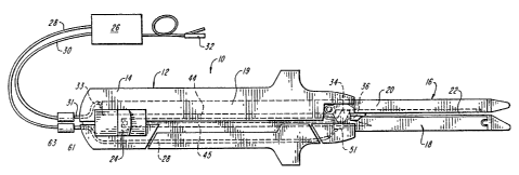
Figure 1 schematically illustrates the surgical cutting
tool of the invention, including a supply source of
electrosurgical energy.
Figure 2 is an exploded side view of the electrosurgical
cutting tool illustrated in Figure 1.
Figure 3 is a sectional view of the electrosurgical tool
of Figure 2 at lines A-A.
Figure 4 is a sectional view of the electrosurgical tool
of Figure 2, at lines B-B.
CA 02122475 2004-O1-09
- 5c -
Figure 5 is a sectional view of the electrosurgical tool
of Figure 2 at lines B-B in an embodiment which does not
include a surgical staple cartridge.
WO 93/08754 PCT/US92/08776
-6-
_z12z~7~
Detailed Description of the Inver,t;r",
Figures 1 and 2 illustrate one embodiment of
the invention in which the surgical cutting tool 10
comprises a housing 12 including a handle portion
14. Adjacent handle portion 14 is cutting template
element 16 which includes a first tyne 1B and a
second tyne 20. The two tynes 18, 20 of cutting
template element 16 are substantially parallel and
define a tissue engaging space 22 into which is
inserted the tissue or organ to be incised. In a
preferred embodiment, the surgical tool 10 includes a
lever 24 which facilitates the movement of a cutting
blade 39 slang a predetermined path.
Figure 1 further illustrates an
electrosurgical generator 26 which serves as an
energy source from which electrical current,
preferably in the radio frequency range, is
communicated to the cutting tool through insulated
wire 28. Insulated wire 30 communicates through
connector 31 and internal ground wire 33 with a
conductive portion of type 20 which serves as a
ground. A control switch 32, preferably in the form
of a foot petal, may be used to control the power
supplied to the cutting tool. Alternatively, a
control switch may be disposed on a portion of the
cutting tool such as the housing 12.
As best shown in Figures 1 and 3. blade 34
can be retracted when not in use. In the retracted
position blade 34 is disposed rearward of the first
tyne 18 within a forward portion of housing 12.
WO 93/08754 212 2 4'~ 5 P~'/US92/08776
.. _
_7_
Blade 34 includes a cutting edge 36 disposed at the
leading edge of the blade. Further, a blade
actuation arm 44 which eztends into housing 12 is
either attached to or integral with blade 34. The
blade 34 is adapted to move along the longitudinal
azis z of the tyne 18 upon actuation of lever 24 in
order to effect the cutting of tissue.
A surgical staple cartridge 38 may
optionally be seated within the first tyne 18, as
illustrated in Figures 1 through 3. Cartridge 38 is
adapted to securely fit within a channel 39 formed in
tyne 18. The staple cartridge 38 includes a central
cutting groove 40 through which the cutting blade 34
passes during a cutting procedure. Dual rows of
openings 92 through which surgical staples (not
shown) emerge straddle either side of groove 40.
As further illustrated in Figures 1 and 3.
lever 24 preferably is connected to the blade 34
through an actuation arm 44. Forward movement of
lever 24 thus effects movement of the blade 34
causing it to traverse the cutting groove 40.
Preferably, a staple ejecting mechanism, such as
ejection arms 45, is actuated simultaneous with
actuation of the blade. In this way staples are
ejected through openings 42 as the blade traverses
the groove 40. As shown in the illustrated
embodiment lever 24 may be connected to ejection arms
45 such that movement of the lever 24 also controls
movement of the ejection arms 45.
WO 93/08754 ~ PCT/US92/08776
2122475 -8-
Figure 5 illustrates an embodiment of the
invention in which the electrosurgical cutting tool
does not utilize surgical staples. In this
embodiment the tissue contacting surface 41 of tyne
18 is constructed of or coated with a non-conducting
material, such as a suitable polymer. Surface 41
defines a cutting groove 43 through which blade 34
travels when it effects a cutting procedure.
As shown in Figure 4, type 20 is secured
within housing segment 12a which preferably is
detachable from housing segment 12b associated with
type 18. Further, tyne 20 has a tissue-contacting
surface 48 which faces first tyne 18. A central
groove 52,is formed in surface 48, superimposable
with cutting grooves 40 or 43 of tyne 18, to
facilitate movement of the blade along longitudinal
axis a.
In an embodiment in which surgical staples
are to be deployed simultaneously with a cutting
procedure, staple cartridge 38 is present within type
18. In addition, surface 48 of tyne 20 includes a
mandrel with a plurality staple-closing depressions
50 which correspond to the openings 42 in staple
cartridge 38. Preferably, dual rows of depressions
are disposed on either side of groove 52. In an
embodiment in which a staple cartridge is not
utilized, the surface 48 may be substantially smooth
and absent depressions 50. In either embodiment,
however, surface 48 of tyne 20 should be made of a
conductive material so that it may serve as a return
electrode for electrical energy delivered through the
cutting blade.
WO 93/08754 21 '~ ,~ ~.'~ ~ PCT/US92/08776
,,.-. -
_g_
In some instances, it may be desirable to
apply electrosurgical energy through the surgical
staples as well as through blade 34. One skilled in
the art could easily modify the electrosurgical
surgical tool described herein by connecting internal
wire 28 to the staple ejection arms 45 as well as to
the blade 34.
Figures 1 through 5 illustrate the
connection of the cutting tool 10 to electrosurgical
generator 26. As illustrated, an inner wire 28
eztends between conductive bushing 51 and electrical
connector 61 which protrudes from housing 12.
Insulated wire 28 may be attached to electrical
connector 61 through connector 63. Bushing 51
communicates electrical curient from the generator 26
to blade 34, directly or through blade actuation arm
44. In a preferred embodiment arm 44 and blade 34
are able to slide within bushing 51 while maintaining
electrical contact therewith.
In a preferred embodiment, the
electrosurgical cutting tool 10 of the invention
comprises a bipolar cutting tool in which the cutting
blade 34 is electrically isolated from the remainder
of the tool and serves as an electrode to deliver
electrosurgical energy to the tissue. In this
embodiment type 20 serves as the return or ground
electrode.. In other embodiments, it is possible that
the surgical tool may comprise a monopolar tool in
which electrosurgical energy is delivered through the
cutting blade 34, and a separate ground plate (not
shown) serves as the return electrode.
WO 93/08754 PCT/US92/08776
212 2 47 ~ -10-
In the preferred bipolar mode surface 48 of
tyne 20 serves as a ground electrode. Accordingly,
exterior ground wire 30 communicates with internal
ground wire 33 through connector 31. Internal ground
wire 33, in turn, is in electrical communication with
a conductive internal anchoring component 19 of tyne
20. Where the cutting device is used in the
monopolar mode. external ground wire 30 should not
communicate with type 20, and the tissue contacting
surface 48 of tyne 20 should be made from or coated
with a non-conductive material.
As noted above, generator 26 supplies
electrosurgical energy to the cutting blade.
Virtually any generator which provides
electrosurgical energy for medical applications may
be used with the present invention. Preferably, the
generator is a voltage determinative. low source
impedance generator which provides radio frequency
energy. Preferably, a suitable generator can supply
up to 2 amps of current and has an impedance value of
less than 10 ohms.
The energy supplied by generator 26 to the
electrosurgical cutting device is preferably in the
radio frequency range. Although virtually any
frequency in the RF range may be supplied to the
cutting device, the preferred frequency range is
about 500 to 700 KHz, and most preferably about 550
3 0 KFi z .
WO 93/08754 ~ ~ 2 ~ ,4'~ ~ PCT/US92/08776
-11-
The energy requirements of the
electrosurgical tool of the present invention are
dynamic and depend to a great extent upon the
impedance values of the tissue encountered by the
blade during cutting procedures. The impedance of
tissue varies among tissue types and the amount of
blood present in or around the tissue. The amount of
current delivered Dy the tool to the tissue is a
function of the impedance of the tissue. Where
tissue contacted has a lower impedance value, more
current will be delivered to the tissue by the blade,
and, conversely, less current will be delivered to
tissue having a higher impedance value. Generally,
the amount of current delivered to tissue ranges
between about 0.5 and 2.0 amps. The voltage applied
to the tissue between the blade and the return
electrode typically is between about 50 to 100 volts
rms.
The surgical tool of the present invention
is particularly well adapted for use in surgical
procedures which require transection of an organ such
as the intestine. in operation, the tissue (e. g.,
intestine) is placed within space 22 defined by types
18 and 20. The blade is moved forward along the
longitudinal axis a of types 18 and 20 by movement of
lever 24. As the blade moves forward, it passes
through the tissue causing it to be severed.
Simultaneously, electrical energy (e. g., radio
frequency energy), which may be activated for ezample
by foot switch 32, is delivered to the tool. The
electrosurgical current is communicated from the
blade 34 to the tissue adjacent the blade and in the
vicinity of the incision.
WO 93/08754 PCT/ US92/08776
-12-
2122475
During a cutting procedure the blade should
be actuated such that it requires approximately 1.5
to 4.5 seconds to move along its predetermined path
to sever tissue. Current should be delivered through
the blade to the tissue during the entire cutting
procedure.
The application of electrical energy in this
manner provides two advantages. Electrosurgical
energy is delivered through the blade to adjacent
tissue to allow for more effective cutting action,
and to promote cauterization and/or tissue fusion
which effectively eliminates all or substantially all
bleeding which results from the incision. The
cauterization and/or fusion effect imparted to tissue
minimizes blood loss and increases the safety of the
surgical procedure as cauterization occurs at
substantially the same time that the incision is
made.
In a preferred embodiment of the invention,
the electrosurgical tool also includes a staple
cartridge 38 which houses a supply of surgical
staples to be supplied adjacent the incision. The
staples may be deployed in one or more linear rows on
either side of the incision to assist in closing the
incision and sealing the severed end of the organ.
The staples are deployed simultaneously with the
cutting action of the blade and the tissue fusion
effect imparted by the electrical energy.
WO 93/08754 ~ ~ ~ ~ PCT/US92/08776
. r ,
-13- ~ ~ ~
One skilled in the art will appreciated that
a variety of materials are well suited for the
manufacture of the electrosurgical tool of this
invention. For example, housing 12 and cartridge 38
may be made from or coated with various
non-conducting polymers. The conductive components
of the tool may be made of various metals, including
surgical grade stainless steel and aluminum.
Although the invention is described with
respect to the cutting tool illustrated in Figures 1
through 5, it is understood that various
modifications may be made to the illustrated
electrosurgical cutting device without departing from
the scope of the invention. For example, a variety
of blade actuation mechanisms may be used. Also, it
is not necessary that types 18 and 20 take on the
shape and orientation illustrated in the drawings.
Moreover, the electrical connection between the
generator may be made in ways other than those
illustrated and described herein. Thus, the present
invention is potentially applicable to virtually all
electrosurgical cutting devices in which a cutting
blade, moveable along a predetermined path, provides
electrosurgical energy to incised tissue
simultaneously with the cutting of tissue.
What is claimed is: