Note: Descriptions are shown in the official language in which they were submitted.
~ PCT/US92/09471
W093/08937 2 1 2 2 ~ ~ 6
-
Title~.C.D AND APPARATUS FOR SIMULTANEOUSLY
FORM~NG FOUR ~ETAL ROUNDS
S~ ~.LCATIOtJ
Field of ~h~ ~nvPn~-i on
T~i8 invention relates to the forming of ~
s diameter ~etal ~v~.~ uc~ as reinforcing bar rounds.
M~re ~re~tfically~ this invention relates to ~et~ods
~nd app~ratus for ~i~ultaneously forming by rolling
four roundfi of unlfor~ ~ize.
Ba~ of I h~ ~nvent~on
The for~ing of ~~11 di~ter rounds from l~rger
bar~ is known in the ~ ng art. Cenerally, ~ large
~r i8 8"c-~FFi~ely p~ hrough a ~er~e of rollers
that reduce the cross cectional area of the b r and,
lS t~u~. a number of internediate ~t-ps, ~ ually
forms the de6ired ~hape. ~ec~u~e the a~ount of the
reduction of the cro~ ~ection~l are~ on each p~s
t~u~h the roller~ ie li~ited, the ~m_ller the cro~
~ectional area of final ~du~, the larger the number
of roller p,aQ~s, m_chinery and production floor space
required.
The ~inulta~ forming of ~ultiple ~v~.db
~ignific~ntly rc'_~e: the ~Lv~e ~Lated pro~lems bec~use
the ,~du~ion in tot~l cro~ ~ectional arQa i~
2s con~iderably le~, therefore, fe~er inter~ediate ~teps
~re required and the ~peed and length of the end
product i~ re~1-o-d.
It is known in th- art to ~imul~neo~ly produce
two un~for~ metal round~ and three un~for~ ~et~l
2 ~ 2 6
-2-
rounds. The simultaneous production of three rounds is described in U.S. Patent
No. 4,357,819.
The additional problems involved in producing four rounds simultaneously
from one bar are significant. The problems include maintaining the uniformity of5 the cross sectional areas of the strands as well as avoiding the cobbling of the
strands during the slitting process. Other considerations include the resistanceproduced when separating the strands, which resistance can result in excessive
heat, lower separating speeds and lower efficiency.
10 Summary of the Invention
This invention discloses apparatus for use in simultaneously forming four
metal rounds. The apparatus includes a first pair and a second pair of forming
rollers. The invention in one aspect comprehends apparatus for use in
simultaneously forming four metal rounds comprising a first pair and a second pair
15 of forming rollers each roller having a forming surface, the first pair and second pair
being connected in series to sequentially pass a bar in a first pass and a second
pass through the roller forming surfaces and each pair having an adjustable
separation distance with the directions of adjustment being substantially non-
parallel. Grooves are in the forming surface of at least one roller of each of
20 the first pair and the second pair, the grooves being dimensioned in combination
to form the bar at the completion of the second pass into four connected strandsof substantially equal cross sectional area . A pair of pre-slitter forming rollers are
connected downstream of the first and second roller pairs having an adjustable
separation distance, the pre-slitter rollers having forming surfaces defining two
25 central grooves and two outside grooves, the four grooves being separated by
three serial ridges with each central groove defining a central groove cross
sectional area and each outside groove defining a strand cross sectional area. The
central groove cross sectional area exceeds the strand cross sectional area by afree space area, the free space area being sufficient to accommodate a variance
30 in strand cross sectional area without requiring redistribution of metal from strands
within central grooves to strands within outside grooves. The pre-slitter grooves
and pre-slitter ridges are dimensioned in combination with the grooves of the first
c;
2 2 6 2 6
-3-
and second forming roller pairs to form a bar comprised of four serial strands of
substantially equal cross sectional area separated by thin connecting portions.
In the preferred embodiment each roller of the first roller pair has a groove
oriented with respect to the entering bar such that each groove forms an end
5 portion of the bar. The separation distance between the surfaces of the first roller
pair determine the width of the bar. The width of the groove in each roller of the
first pair determines the cross-sectional height of an end portion of the bar.
In the preferred embodiment the rollers of the second pair are oriented with
respect to the entering bar such that the separation distance between the roller10 surfaces determines the height of the central portion of the bar. In addition, in the
preferred embodiment, the rollers of the second pair have ridges for forming the bar
into four portions separated by thick connecting portions.
In the preferred embodiment the ridges of the pre-slitter roller have outside
and inside slope angles of approximately 30~.
The invention discloses further apparatus for use in simultaneously forming
metal rounds from a bar guided to the apparatus, the bar being comprised of fourserial strands, two outside and two middle, separated by thin connecting portions.
Another aspect of the invention provides apparatus for use in simultaneously
forming metal rounds from a bar guided to the apparatus, the bar being comprised20 of four serial strands, two outside and two middle, separated by thin connecting
portions. The apparatus comprises a first pair of slitter rolls, a first ridge and a
second ridge on each roller of the first pair, the first ridges being located tocorrespond with a thin portion connecting a first outside strand to a first middle
strand, the second ridges being located to correspond with a thin portion
25 connecting a second outside strand to a second middle strand, each ridge having
an outside ridge slope angle greater than an inside strand slope angle of a
corresponding portion of the outside strand. Means is serially connected
downstream of the first pair of slitter rolls, for separating the two middle strands.
A
In the preferred embodiment the outside slope angles of the ridges of the first
slitter rollers exceed the inside slope angles of the corresponding portions of the
outside strands by approximately 22~. Further, it has been found effective if the
outside slope angle of the ridges of the first slitter rollers are approximately 52~.
The apparatus may further include inside slope angles for each ridge of the
first slitter rollers that are less than the outside slope angle of the corresponding
middle strand. It has been found effective if the inside slope angles of the first slitter
rollers are approximately 25~.
In the preferred embodiment the means for separating the two middle strands
is comprised of a slitter roller pair wherein at least one roller has a ridge located to
correspond to the thin connecting portion between the two metal strands. The slope
angles of the second slitter roller ridge are greater than the corresponding inside
slope angles of the middle strands. It has been found effective if the inside slope
angles of the ridge exceed the corresponding inside slope angles of the middle
strands by approximately 5~. Thirty-five degrees (35~) has been found to be an
effective slope angle for the ridge of the second slitter roller.
The invention discloses a method for forming a bar to be slit
and simultaneously formed into four metal rounds that comprises adjusting the
separation distance between a first pair of forming rollers and between a second pair
of forming rollers. The method includes passing a bar by the first pair
of rollers to form a bar of fixed cross-sectional width and fixed
cross-sectional height over end portions of the bar and passing the
bar by the second pair of rollers to form a bar of
6 :~ ~
-5-
fixed cross-sectional height over central portions of the bar. The method includes,
subsequent to the above steps, passing the bar by a pair of pre-slitter rollers. The
pre-slitter rollers have three ridges for forming four serial strands of approximately
equal cross-sectional area separated by thin connected portions.
The invention also discloses a method of slitting a bar comprised of four
serial strands, two outside and two middle, of approximately equal cross-sectional
area separated by thin connecting portions. The invention also pertains to a
method for slitting a bar comprised of four serial strands, two outside and two
middle, of approximately equal cross sectional area separated by thin connectingportions, comprising passing the bar by a first pair of slitter rollers, each having
two ridges with interfering outside ridge slope angles and noninterfering insideridge slope angles, thereby separating a first outside strand from a first middle
strand and a second outside strand from a second middle strand by applying a
lateral force with portions of an outside surface of a ridge to portions of an inside
surface of an outside strand without applying significant lateral force with an inside
surface of a ridge to an outside surface of a middle strand, and subsequently
separating the two middle strands.
Brief Description of the Drawings
Fig. 1 comprises a schematic plan view of a series of connected forming and
slitting rollers of the preferred embodiment.
Fig. 1 A comprises a schematic elevational view of a roller stand.
Figs. 2A through 2G illustrate the bar subsequent to the forming passes, the
slitting passes and further forming passes.
Fig. 3A is an elevational view of one of a pair of forming rollers.
Fig. 3B is an elevational view of one of a pair of forming rollers.
Fig. 4 is an elevational view of one of a pair of pre-slitter rollers.
Fig. 5 is an elevational view of a slitter roller.
Fig. 5A is an illustrative view of the interaction of a bar formed into strands
s with a slitter roller.
Fig. 5B is an illustrative closeup of a detail of the interaction of the ridge of
a slitter roller with the sides of the strands of a bar.
Fig. 6 is a view of a single ridge slitter roller.
Fig. 6A is a view of a bar separated into four strands connected by thin
10 connecting portions.
Description of the Preferred Embodiment
A conventional roller stand S is schematically shown in Fig. 1 A. An
elevational view of a roller pair that would be utilized toward the end of the process
of simultaneously forming four metal rounds is illustrated. As shown, two cylindrical
rollers 154 are mounted within frame 99. The longitudinal axes of the rollers are
shown horizontal to the floor. The two rollers are further illustrated as being placed
vertically parallel to each other, one on top of the other. This presumption of a
horizontal and vertical alignment of the rollers has been adopted herein for
convenience. Those skilled in the art would understand that the roller stand could
20 be rotated such that the aforementioned vertical and horizontal directions could
assume other directions.
When rollers 154 of Fig. 1A are rotated in the direction indicated by the
arrows, the bar of metal, now separated into four strands, will be drawn through the
rollers and would move in a direction out of and perpendicular to, the surface of the
paper. The bar, or strands, may be regarded as having a length, a width and a
height. The width and the height are cross sectional dimensions. Rollers 154
predominately form and affect the cross sectional dimensions of the bar or strands.
In roller stand S, the axes of the rollers, indicated by dashed lines 166 and
5 168, are usually adjustable with respect to each other. This permits adjustment of
the separation distance between the surfaces of the rollers. The adjustability of the
axes is indicated by the arrows 171 associated with axes 166 and 168. The
separation distance between the rollers affects the form of the bar and the cross
sectional area of the strands created. The ability to vertically adjust the rollers also
10 permits compensation for wear of the roller surfaces.
The cylindrical surfaces of the rollers are conventionally sculpted, or
dimensioned, to contain circumferential grooves 170 and ridges 172. A ridge, as the
word is used herein, may present a flat top surface, as illustra~ed in Fig. 1A, or may
rise to a nearly pointed or a pointed surface, as in roller 144 of Fig. 1 . The grooves
15 and ridges serve to form the bar in a pass. The cross sectional area of the bar will
exhibit a configuration conforming or semi-conforming to the cross sectional area
between the rollers. The degree of conformation depends upon the design of the
rollers and the extent to which they contain free space in or around the grooves.
The grooves are designed with respect to the anticipated cross sectional area
20 of the incoming bar. The separation distance of the rollers may be adjusted such
that the metal of the bar is forced to flow into, conform to and fill all of the space
of the groove. Excess metal, in such case, may move during the pass
WO 93/08937 212 2 ~ 2 6 pcTlusg2lo9471
-8-
toward the free space at the side of the rollers. The grooves may
also be designed, in conjunction with the separation distance, to a
depth that defines a free space therein. The free space serves to
substantially eliminate the flow of metal from a groove during a
pass.
The preferred embodime,lt illustrated herein assumes that
the grooves and ridges of a roller pair are sculpted identically onto
the face of each roller to form a matched pair. However, it will be
appreciated by those skilled in the art that the invention may
function if the rollers of a roller pair are designed with nonmatcl,illg
grooves and/or ridges.
The term "slope angle" is used herein. "Slope angle" as it is
used indicates the angle between the "vertical" and a tangent
drawn to a point on a ridge or a strand. A "vertical" in regard to a
strand is perpendicular to the axis of the rollers of the previous
roller pair that passed and formed the strand. Reference is made to
"inside" and "outside" "slope angles" of ridges and strands.
"Inside" refers to either an inside element or a side facing toward
the inside of the rollers or the inside of the strand. "Outside"
refers to either an outside element or a side facing toward the
outside of the rollers or the outside of the strand. When this
reference is used, it is to be understood that, with respect to a
strand, only the slope angles of "central portions" of sides of a
strand are indicated. When the "slope angle" of a ridge of the
roller is referred to, it is to be understood that only the slope angles
of portions of the ridge that "correspond to" central portions of a
corresponding side of a strand are indicated.
For instance, in Fig. 4 the area designated 90 illustrates the
portions of ridges 146, 147 and 148 that correspond to the slope
angles of central portions of the strands formed by the ridges. In
Fig. 5B the areas designated 165 and 166 comprise illustrative
central portions of sides of a strand.
The slope angle of the strands in their "central portions" is
referred to because it is against these
side walls of the strands that the slitter rollers, to be discussed below, either
do or do not "interfere", or do or do not exert a lateral force. As discussed
below, a lateral force can be exerted by a ridge of a slitter roller. When this
ridge exerts the lateral force, it is said that the ridge has a slope angle, at
least in portions corresponding to central portions of the strand, that would
"interfere" with the slope angle of the strand.
The actual slope angle in "non-central" portions where, for instance,
strand 150b or strand 150c, as illustrated in Fig. 5B, intersect the thin
connecting portion separating the two strands, is not so significant. It is the
slope angle along the "central portions" of the side slope of the strand that
is important. These central portions either will receive a lateral force from the
interference of the slitter roller slope angle or there will be no interference.For instance, as illustrated in Fig. 5B, which is included for illustrative
purposes, not as part of the preferred embodiment, one ridge of slitter roller
160 is shown inserted within or between the side walls of strand 1 50c and
1 50d to the point where it touches or virtually touches the thin connecting
portion. It may be that where the peak of the ridge on slitter roller 160 meets
or almost meets the thin connecting portion, the slope angle of the ridge is
in fact less than the slope angle of strands 1 50d.
As illustrated in Fig. 5B, the slope of the inside central portion of the
wall of strand 1 50d is defined by the angle between tangent 1 12 drawn to
that inside strand wall and vertical 122. This angle is illustrated as angle 106in Fig. 5B. The slope of the corresponding central portion of the ridge of the
slitter 160 is illustrated by angle 104 drawn between vertical 122 and
tangent 1 19 drawn at a "central portion" of the outside of the ridge of slitterroller 1 60.
-10-
Similarly, when measuring the relative slope angles of the inside
surface of the slitter ridge vis-a-vis the outside surface of strand 150c, the
relevant central portion of strand 150c is denominated by numeral 166 in Fig.
5B. Tangent 117 drawn to a point on a central portion of strand 150c makes
angle 100 with vertical 122. Tangent 121 drawn to a corresponding central
portion of the ridge of slitter roller 160 makes angle 102 with vertical 122.
The relative sizing of angles 104 and 106 and angles 100 and 102 determine
whether the ridge of the slitter roller interferes, or does not interfere, with the
side wall of the strand.
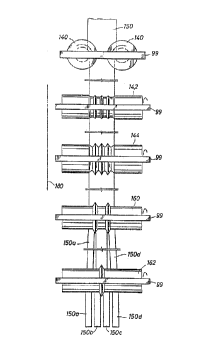
As schematically shown in Fig. 1, a metal bar 150 moves in the
direction of arrow 180 past five roller stands. First rollers 140 are shown
installed with their axis of rotation in the vertical direction. Since the
schematic view is presented as from above and the following four roller pairs
are illustrated as installed vertically, one above the other, only one roller ofthe subsequent four pairs, roller 142, roller 144, roller 160 and roller 162, isshown. For the same reason rollers 140 have a central groove 139 that is
not shown in Fig.1 but is shown in Fig. 3A.
As bar 150 proceeds through the series of roller stands in the
direction of arrow 180, it takes on new cross sectional shapes as a function
of the shape of the grooves and the ridges found in the surface of the rollers
and to some extent, of the separation distance between the rollers in a pair.
Rollers 160 and 162 are stirrer rollers. As illustrated in Fig.1, roller
160 slits bar 150 into a central portion and two outside strands, 150a and
150d. Slitter roller 162 slits the central portion of bar 150 into strands 150b
and 1 50c.
After the four separated strands emerge from slitter roller 162, they
will be formed into metal rounds by a further series of forming rollers, as is
known in the art. Such forming rollers are not illustrated in Fig. 1.
As mentioned above, the dimensioning of the grooves and ridges on
the roller surfaces, as well as the adjustment of the separation distance
between the rollers of a pair, determines the effect the grooves and ridges
have upon the metal bar passing the stand. Such effect is illustrated for the
preferred embodiment in Figs. 2A through 2G.
Fig. 2A illustrates rollers 140 installed with their axes of rotation in
the vertical direction. Fig. 3A illustrates one forming roller 140 in greater
detail. The separation distance between the roller 140 surfaces is established
such that one central groove 139 in each roller conforms each end portion of
bar 150 to the dimensions of the groove. The adjustment of the separation
distance between rollers 140 determines the width of the bar. The height of
groove 139 determines the height of each end portion of bar 150 as it passes
rollers 140. Free space 141 between the rollers accommodates the flow of
any excess metal from the ends of the bar into the central portion of the bar.
Rollers 142 of Fig. 2B are illustrated installed with their axes of
rotation in the horizontal direction, as are all succeeding roller pairs. Fig. 3B
illustrates one roller 142 in greater detail. Rollers 142 have sculpted in theirsurface a series of grooves 1 43a and flat ridges 143. The separation distance
between rollers 142 is adjusted such that the metal of the bar fills the space
in the central portion of the rollers between the roller surfaces. Thus, the
-12-
height and shape of at least the central portion of the bar is formed by rollers142. Excess metal is accommodated by being permitted to flow to the
outside space between the two rollers.
Those skilled in the art will appreciate that bar 150 is guided between
s roller pairs 140, 142, 144 and the slitter rollers. Thus, the grooves and
ridges of one roller pair can be aligned in combination with the grooves and
ridges of a prior roller pair. They can be dimensioned in combination to create
an effect in sequence.
Both rollers 144 in the preferred embodiment contain three ridges
146, 147 and 148. Although it is preferred that both rollers contain the
ridges, one roller with the ridges could suffice. Fig. 4 illustrates one roller
144 in greater detail. Ridges 146, 147 and 148 are dimensioned to establish
four strands in bar 150, namely 150a, 150b, 150c and 150d. The four
strands are connected by thin connecting portions. Strands 150a and 150d
are outside strands. Strands 150b and 150c are middle strands. Ridges 146,
147 and 148 not only establish thin connecting portions between four serial
strands but also establish certain slope angles that the strands assume.
Roller pair 144 also contains two central grooves 145 that provide for
free space 145a above middle strands 150b and 150c formed in grooves
145. The free space permits the forming of the thin connecting portions by
the rollers of pair 144 without redistributing metal from the middle strands to
the outside strands. The free space accommodates a certain variance in
cross sectional area of middle strands 150b and 150c.
Slitter rollers 160, one of which is illustrated in Fig. 5, will slit the bar
- 13 -
150 comprised of four serial strands 150a, 150b,150c and 150d connected
by thin connecting portions, as illustrated in Fig. 2C, into a middle portion
comprised of strands 150b and 150c still connected by a thin connecting
portion and separate outside strands 150a and 150d, as illustrated in Fig.2D.
Slitter rollers 162, one of which is illustrated in Fig. 6, separates
middle section 150b and 150c connected by thin connecting portions, as
illustrated in Fig. 2D, into two separate strands 150b and 150c as illustrated
in Fig. 2E. Figs. 2F and 2G illustrate a subsequent working of the four
separated strands 150a, 150b, 150c and 150d by rollers by 152 and rollers
154 into four uniform rounds. This subsequent simultaneous working,
illustrated in Figs. 2F and 2G, is understood by those skilled in the art.
Hence, the details of such working will not be further discussed.
In a review of Figs. 2A and 2B, it can be seen that bar 150 as it
emerges from rollers 140 has a predetermined width and the height of its end
portion is determined. Bar 150 as it emerges from rollers 142 of Fig. 2B has
the height of its central portion determined. In the preferred embodiment, bar
150 as it emerges from rollers 142 contains in fact four portions separated
by thick connecting portions, the thick connecting portions being formed by
ridges 143. Bar 150, after completing the pass of rollers 140 and 142, is
known to be divided, by one who is informed of the dimensions of rollers 140
and 142, into four portions of substantially equal area.
One problem to be solved in the simultaneous forming of four metal
rounds is maintaining the uniformity of the cross sectional area of the four
metal rounds. That is, the diameter of the rounds should conform to
specifications within a certain tolerance. The words "substantially equal
-14-
area" are used herein to indicate that the cross sectional area of the four
portions would, if formed into rounds, have diameters that conformed to the
specifications within the given tolerances.
In the preferred embodiment, the passes are arranged such that the
bar passes first through rollers 140 and then past rollers 142. Reversing the
progress through the first two pair of forming rollers, i.e. putting rollers 140downstream of rollers 142, should yield a somewhat equivalent result. That
is, bar 150 subsequent to both passes could be divided into four portions of
substantially equal cross sectional area.
As discussed above, the first two passes by the forming rollers
conform entering bar 150 to four portions of substantially equal cross
sectional areas. Pre-slitter rollers 144 separate the bar into four strands
separated by thin connecting portions. The substantially equal cross sectional
area is maintained. Pre-slitter rollers 144 also establish slope angles of the
strand.
In the preferred embodiment, the two outside strands are first slit
from the two middle strands by slitter rollers 160. Subsequently, the two
middle strands are slit by slitter rollers 162. This is illustrated in Fig.1 andFigs. 2d and 2e. The slitting is performed by applying a lateral horizontal
force to the walls of the strands, effecting a tearing along the thin connectingportions. The lateral force is delivered by the interference of the slope angle
of a side of a ridge of the slitter roller with the slope angle of a corresponding
side of a strand. In the process of separating off the two outside strands
with slitter rollers 160, ridge angle 118 is designed in combination with the
ridge angles 146 and 148 of pre-slitter rollers 144 such that the slitter roller
ridge angle is greater than the strand 150a or 150d inside slope angle. In the
preferred embodiment the difference in the angle 118 and the angles 146 or
148 is approximately 22~. Angle 118 is preferably approximately 52~ while
angles 146 and 148 are approximately 30~.
s In the preferred embodiment, the inside slope angles of the ridges of
slitter roller 160, that is, the angle formed by side 120, is less than the
outside slope angle of strands 150b and 150c. The difference is
approximately 5~. In the preferred embodiment the outside slope angle of
strands 150b and 150c are approximately 30~ while the inside slope angles
of the ridges of roller 160 are approximately 25~. In such a fashion, lateral
separating forces are applied to strands 150a and 150d without applying a
friction force to the two captive inside strands 150b and 150c.
Although the side walls of the ridges of slitter roller 160, as illustrated
in Figs. 5 and 5A, are shown approximately straight, i.e. side walls 118 and
120, it should be understood that the side walls of the ridge of slitter roller
160 could assume a continuously curved configuration. They should be
designed in conformity with a similarly curved configuration given to strands
150a, 150b, 150c and 150d, at least in their central portions, by the ridges
146, 147 and 148 of pre-slitter rollers 144.
As illustrated in Figs. 6 and 6A, inside edge 134 of the ridge of
second slitter roller 162 forms angle 138 with a vertical 132. The inside
slope angles of strands 150b and 150c make angle 97 between tangents 98
and vertical 112. In the preferred embodiment, angles 138 are greater than
angles 97. In fact, angles 138 exceed angles 97 by 5~. In the preferred
embodiment, the inside slope angle 97 is essentially 30~ and the ridge
-16-
outside slope angles are essentially 35~. With such arrangement, second
slitter roller 162 applies a lateral force and separates by tearing strand 1 50bfrom strand 1 50c.
The foregoing disclosure and description of the invention are
illustrative and explanatory thereof. Various changes in the size, shape and
materials as well as the details of the illustrated construction may be made
without departing from the spirit of the invention.