Language selection

Search

Patent 2122735 Summary

Third-party information liability

Some of the information on this Web page has been provided by external sources. The Government of Canada is not responsible for the accuracy, reliability or currency of the information supplied by external sources. Users wishing to rely upon this information should consult directly with the source of the information. Content provided by external sources is not subject to official languages, privacy and accessibility requirements.

Claims and Abstract availability

Any discrepancies in the text and image of the Claims and Abstract are due to differing posting times. Text of the Claims and Abstract are posted:

  • At the time the application is open to public inspection;
  • At the time of issue of the patent (grant).
(12) Patent: (11) CA 2122735
(54) English Title: OSCILLATOR FREQUENCY DIVIDE-DOWN TRANSMIT OFFSET SCHEME FOR REDUCING SELF-QUIETING
(54) French Title: METHODE DE PRODUCTION D'UNE FREQUENCE DE DECALAGE PAR DIVISION DE LA FREQUENCE D'UN OSCILLATEUR POUR MODE D'EMISSION
Status: Deemed expired
Bibliographic Data
(51) International Patent Classification (IPC):
  • H04B 1/40 (2015.01)
  • H04B 15/04 (2006.01)
  • H04B 1/40 (2006.01)
  • H04Q 7/32 (2006.01)
(72) Inventors :
  • MARKO, PAUL D. (United States of America)
  • BORRAS, JAIME A. (United States of America)
(73) Owners :
  • MOTOROLA, INC. (United States of America)
(71) Applicants :
(74) Agent: GOWLING WLG (CANADA) LLP
(74) Associate agent:
(45) Issued: 1998-12-22
(86) PCT Filing Date: 1992-10-30
(87) Open to Public Inspection: 1993-05-13
Examination requested: 1994-05-02
Availability of licence: N/A
(25) Language of filing: English

Patent Cooperation Treaty (PCT): Yes
(86) PCT Filing Number: PCT/US1992/009304
(87) International Publication Number: WO1993/009606
(85) National Entry: 1992-10-30

(30) Application Priority Data:
Application No. Country/Territory Date
07/787,279 United States of America 1991-11-04

Abstracts

English Abstract


A radio communication device (10) having a receive mode and a transmit mode, includes a receiver portion, a transmitter
portion, and multiple oscillators for providing reference waveforms for the radio communication device (10). During the receive
mode, the receiver portion receives signals having a selected frequency, converts received signals to at least a first intermediate
frequency (1F), and a transmitter oscillator (44) produces a first waveform having a frequency equal to a multiple of the first
intermediate frequency during the receive mode. During the transmit mode, the transmitter portion requires a reference waveform
having an offset frequency equivalent to the first 1F frequency to produce a radio frequency signal. Thus, the radio communication
device also comprises a divider (48) coupled to the transmitter oscillator (44) for dividing the frequency of the first waveform
to the required offset frequency in the transmit mode.


French Abstract

Dispositif de radiocommunication (10) comprenant un mode de réception et un mode d'émission. Le dispositif est constitué d'un récepteur, d'un émetteur et de nombreux oscillateurs qui lui (10) assurent une forme d'onde de référence. Lorsqu'il est en mode de réception, le receveur reçoit des signaux d'une fréquence choisie, convertit ces signaux en au moins une première fréquence intermédiaire (IF) et un oscillateur d'émission (44) produit une première forme d'onde dont la fréquence est égale à un multiple de la première fréquence intermédiaire au cours du mode de réception. En mode d'émission, l'émetteur nécessite une forme d'onde d'une fréquence décalée équivalent à la première fréquence IF afin de produire un signal de fréquence radio. Le dispositif de communication radio comprend également un diviseur (48) raccordé à l'oscillateur d'émission (44) afin de diviser la fréquence de la première forme d'onde en vue d'obtenir la fréquence décalée requise en mode d'émission.

Claims

Note: Claims are shown in the official language in which they were submitted.


THE EMBODIMENTS OF THE INVENTION IN WHICH AN EXCLUSIVE
PROPERTY OR PRIVILEGE IS CLAIMED ARE DEFINED AS FOLLOWS:


1. A radio transceiver, having a receive mode and a transmit mode, comprising:
a receiver for receiving signals having a selected frequency, the receiver
comprising means for converting received signals to at least one intermediate
frequency;
a transmitter for transmitting signals at said selected frequency;
oscillator means, coupled to the receiver and to the transmitter, including
an output for providing a waveform having a frequency f0 to the transmitter, thefrequency f0 being a multiple of the at least one intermediate frequency; and
divider means, coupled between the output of the oscillator means and
the transmitter, for dividing the frequency f0 by a predetermined amount during
the transmit mode.

2. The radio transceiver of claim 1 wherein the means for converting
received signals to at least one intermediate frequency comprises a mixer.

3. The radio transceiver of claim 1 further comprising switch means for
turning off the divider means during the receive mode.

4. A radio transceiver having a receive mode and a transmit mode, the
radio transceiver comprising:
frequency synthesizer means for synthesizing reference waveforms, the
frequency synthesizer means including:
a first loop for providing a first waveform having a first intermediate
frequency; and
a second loop for providing a second reference waveform having a
second frequency, the second frequency being a multiple of the first frequency;
the second loop comprising a divider for dividing the frequency of the
second waveform to provide a third waveform having a frequency equal to the
first intermediate frequency; and
switch means coupled to the divider for turning on the divider during the
transmit mode and for turning off the divider during the receive mode.


5. In a radio transceiver having a receive mode and a transmit mode, a
method for reducing self-quieting comprising:
providing a reference waveform providing a frequency f0 with an
oscillator during the receive mode;
dividing the frequency f0 using a divider by a predetermined amount
during the transmit mode; and
quickly switching the divider from on to off when said radio transceiver
switches from transmit to receive and quickly switching the divider from off to on
when said radio transceiver switches from receive to transmit.

Description

Note: Descriptions are shown in the official language in which they were submitted.


W093/09~6 2 1 2 2 7 ~ 5 PCT/US92/09304
_


OSCILLATOR FREQUENCY DIVIDE-DOWN TRANSMIT OFFSET SCHEME FOR
REDUCING SELF-QUIETING


Technical Field
This invention relates generally to radio communication
15 devices, and more specifically to radio communication devices
using time division multiplexing.

Back~round
Many modern communication systems use time division
20 multiplexing. Radios in such multiplexed systems switch rapidly
between the receive and transmit modes. Such radios may
include oscillators that provide reference waveforms for both the
receiver and transmitter portions of the radios. A problem may
arise in such radios when an oscillator in the radio produces a
25 signal having a frequency equal to the receive frequency, or to an
intermediate frequency of the receiver, because in many cases,
the oscillator cannot be turned off sufficiently fast to prevent its
output from being received by the receiver when the radio goes
into its receive mode. These oscillator signals interfere with the
30 performance of the radio because the receiver receives the
oscillator signals instead of desired signals. This phenomenon is
known as self-quieting, and is obviously undesirable. One
possible solution to the self-quieting problem is to shield the
receiver portion of the radio so that the oscillator signals are not
35 received during the receive mode. However, shielding of a
receiver requires space and may not be as effective as desired.

2 ~

Thus, a need exists for a method and apparatus for reducing self-
quieting that avoids the detriments of shielding.

Summary of the Invention
Briefly, according to the invention, a radio communication
device, having a receive mode and a transmit mode, includes a
receiver portion, a transmitter portion, and multiple oscillators for
providing reference waveforms for the radio communication
device. During the receive mode, the receiver portion receives
signals having a selected frequency, converts received signals to
at least a first intermediate frequency (IF), and a transmitter
oscillator produces a first waveform having a frequency equal to a
multiple of the first intermediate frequency during the receive
mode. During the transmit mode, the transmitter portion requires
a reference waveform having an offset frequency equivalent to
the first IF frequency to produce a radio frequency signal. Thus,
the radio communication device also comprises a divider coupled
to the transmitter oscillator for dividing the frequency of the first
waveform to the required offset frequency in the transmit mode.
Brief Description of the Drawings
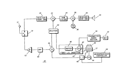
FIG.1 is a block diagram of a radio transceiver 10 in
accordance with the invention.

Detailed Description of the Preferred Embodiment
Referring to FIG. 1, there is shown a radio transceiver 10
using an offset scheme in accordance with the invention.
The radio transceiver 10 comprises receiver and transmitter
portions. The radio 10 is a time division duplex radio which
transmits and receives at the same frequency. Thus, an antenna
switch 14 (possibly an integrated circuit) switches periodically
between the receive and transmit modes. The radio transceiver
10 further comprises a microprocessor 64 for controlling its
operation.
In the receive mode, an antenna 12 receives radio
frequency (RF) signals at a frequency selected by its user (e.g.,

~O 93/09606 2 I 2 2 7 3 5 PCI/US92/09304

between 864 and 868 MHz). A receiver front end 16 receives the
RF signal from the antenna 12 and processes it for mixing with a
first injection waveform at mixer 22. The receiver front end 16
includes conventional frequency selective circuitry to select the
5 proper signals. The outptut of the receiver front end 16 is
multiplied with a reference waveform (having a frequency of 819-
823MHz, in this example) at the first mixer 22. The output of the
mixer 22 is ~pp'!ed to surface acoustic wave (SAW) filter 24
(having a center frequency of 45 MHz) to produce a first
1 0 intermediate-frequency (IF) signal. A second down mixer 26
mixes the first IF signal with a 34.3 MHz reference waveform
(produced with an oscillator 36). The oùtput of the second mixer
is ~ppliQd to a receiver back end 28 where it is amplified and
r~l with a 10.7 MHz bandpass filter (within the receiver back
1 5 end 28) to produce a second IF signal. A demodulator circuit
(also within the receiver back end 28) demodulates the second IF
signal and extracts data therefrom to present the data or audio to
a user (possibly via a speaker 30).
In the transmit mode, a microphone 32 receives voice
20 signals from the user of the radio 1 û, and applies them to a
transmitter audio section 34. The transmitter audio section 34
includes conventional audio circuitry. The output of the audio
section 34 is then applied to an injection circuit 40 at a VCO 42
which operates with a frequency synthesizer 37 to modulate a
25 reference waveform (or carrier) with the information signals
provided by the audio section 34. The output of the VCO 42 is
buffered (46) to avoid frequency pull problems. A splitter 54
provides output of the buffer 46 to transmitter up-mixer 56 and
receiver mixer 22. The mixer 56 multiplies the output of the
30 splitter 54 with a 45 MHz reference waveform to produce a radio-
frequency signal for transmission. The mixer 56 drives a
bandpass filter 60 (preferably an 866 MHz stripline filter) which
removes out-of-band components of the signal provided at the
' mixer 56. The synthesizer 37 is also coupled to VCO 44 to
35 provide an injection signal to mixer 56. A power amplifier 62

WO 93/09606 PCI/US92/09' - '
2122735

amplifies the output of the bandpass filter 60 to a level suitable for
transmission.
The synthesizer 37 is of a conventional design and is
coupled to a cr,vstal 38 for synthesizing signals. In accordance
5 with the invention, the VCO 44 provides a waveform having a
frequency of 90 MHz. This frequency is twice what is required at
the mixer 56 to convert the modulated signal to the transmit
frequency. Accordingly, a divide-by-two divider 48 divides the
frequency of the output of VCO 44 by two. The divider 48, unlike
10 the VCO 44, can be turned on and off very quickly. Thus, when
the radio 10 switches from transmit to receive, the divider 48 is
turned off by the microprocessor controller 64. Therefore, during
the receive mode the transmitter portion of the transceiver does
not produce a 45 MHz waveform and the self-quieting problem is
15 at least reduced.
Therefore, the invention solves the self-quieting problem
by operating the transmit oscillator at a multiple of the required
frequenc,v during the receive mode, and the output of the
oscillator is frequency-divided to the desired frequency in the
20 receive mode.

What is claimed is:

Representative Drawing
A single figure which represents the drawing illustrating the invention.
Administrative Status

For a clearer understanding of the status of the application/patent presented on this page, the site Disclaimer , as well as the definitions for Patent , Administrative Status , Maintenance Fee  and Payment History  should be consulted.

Administrative Status

Title Date
Forecasted Issue Date 1998-12-22
(86) PCT Filing Date 1992-10-30
(85) National Entry 1992-10-30
(87) PCT Publication Date 1993-05-13
Examination Requested 1994-05-02
(45) Issued 1998-12-22
Deemed Expired 2002-10-30

Abandonment History

There is no abandonment history.

Payment History

Fee Type Anniversary Year Due Date Amount Paid Paid Date
Application Fee $0.00 1992-10-30
Maintenance Fee - Application - New Act 2 1994-10-31 $100.00 1994-09-26
Registration of a document - section 124 $0.00 1994-10-21
Maintenance Fee - Application - New Act 3 1995-10-30 $100.00 1995-09-28
Maintenance Fee - Application - New Act 4 1996-10-30 $100.00 1996-09-24
Maintenance Fee - Application - New Act 5 1997-10-30 $150.00 1997-09-19
Final Fee $300.00 1998-08-07
Maintenance Fee - Application - New Act 6 1998-10-30 $150.00 1998-09-22
Maintenance Fee - Patent - New Act 7 1999-11-01 $150.00 1999-09-16
Maintenance Fee - Patent - New Act 8 2000-10-30 $150.00 2000-09-20
Owners on Record

Note: Records showing the ownership history in alphabetical order.

Current Owners on Record
MOTOROLA, INC.
Past Owners on Record
BORRAS, JAIME A.
MARKO, PAUL D.
Past Owners that do not appear in the "Owners on Record" listing will appear in other documentation within the application.
Documents

To view selected files, please enter reCAPTCHA code :


To view images, click a link in the Document Description column. To download the documents, select one or more checkboxes in the first column and then click the "Download Selected in PDF format (Zip Archive)" or the "Download Selected as Single PDF" button.

List of published and non-published patent-specific documents on the CPD .

If you have any difficulty accessing content, you can call the Client Service Centre at 1-866-997-1936 or send them an e-mail at CIPO Client Service Centre.


Document
Description 
Date
(yyyy-mm-dd) 
Number of pages   Size of Image (KB) 
Representative Drawing 1998-12-18 1 7
Cover Page 1998-12-18 2 66
Claims 1995-07-29 2 68
Description 1998-04-14 4 167
Claims 1998-04-14 2 62
Drawings 1998-04-14 1 18
Cover Page 1995-07-29 1 19
Abstract 1995-07-29 1 59
Drawings 1995-07-29 2 37
Description 1995-07-29 4 189
Correspondence 1998-08-07 1 32
Fees 1996-09-24 1 78
Fees 1995-09-28 1 76
Fees 1994-09-26 1 77
Fees 1994-09-26 1 84
National Entry Request 1994-05-02 6 276
Prosecution Correspondence 1994-05-02 8 302
Prosecution Correspondence 1997-12-19 2 35
Examiner Requisition 1997-06-20 2 61
International Preliminary Examination Report 1994-05-02 15 374
Prosecution Correspondence 1994-05-02 1 28