Note: Descriptions are shown in the official language in which they were submitted.
3 ~ 3 ~ ~
-
PROCESS AND DEVICE FOR TAKING
REPRESENTATIVE MILK SAMPLES
The invention relates to a process for taking a representative milk
sample during delivery of a milk charge of a supplier from a tank via a deliveryline into a collecting tank, and also to a device for performing this process.
In a process and device of this kind it is important to take milk samples
which are representative and have a reproducible volume. In order to do so it isnecessary to know the amount of milk supplied by the respective supplier, and
to input this amount into a data acquisition means so that the sample bottle forreceiving a milk sample is constantly filled as a result of this parameter.
As the aim is to take a representative milk sample for the entire milk
charge supplied, the milk sample removal process must be controlled as a
function of the total milk charge volume. The term: "representative milk sample"is understood to mean that only a maximum volume is available in the sample
bottle intended for the milk sample and that, if possible, the milk sample should
have a roughly constant volume, independently of whether a small volume milk
charge or a very large milk charge is delivered. A constant volume for the milk
sample is necessary because certain minimum quantities are required for
investigating and testing the milk sample.
However, another objective of obtaining a representative milk sample
is to draw the sample over the entire delivery and suction cycle of the
corresponding milk charge. However, since, as a function of the volume, the milkcharges are suctioned with different delivery capacities, e.g. from a tank and
pumped into the milk collecting truck, so that different delivery times occur, which
must also be taken into account when obtaining a representative milk sample.
Another aspect of taking a milk sample relates to the entrainment-free
sampling, which is substantially guaranteed by taking the sample via a suction
line.
DE 35 02 858 A1 discloses a milk sampling process and device which
partially take into account the above-mentioned aspects. Measurement of the
delivery flow is carried out with the help of a magnetic-inductive flow meter (MID).
- 1 -
' - -
An air detector is also provided, which switches off the device or signals a
malfunction when a pre-determined amount of air in the delivery line is exceeded.
A conductivity switch serves as signal transmitter for a mechanism by which an
outlet funnel can be adjusted to perform a programmed rinsing of the milk line at
5 the beginning of a milk sample removal.
In this process and device, however, one does not account for the fact
that the delivered milk charge contains quantitatively differing air admixtures as
a function of the delivery time. This is particularly the case at the end of a
delivery when, as in the case of fat milk, the cream portion floating on top of the
10 milk, which represents an important quality characteristic for the supplier, is
suctioned off. With this type of sampling, however, this cannot be performed in
the desired way due to air bubbles.
Further, the generation of air bubbles in the milk depends on the skill
and constancy of the staff member suctioning off the milk at the time. Human
15 error sources strongly influence the delivery capacity and time, when taking over
a milk charge from a tank into the milk collecting truck or into another tank, and
also affect the relevance of the information obtained from the sampling.
Further, it is known from DE 40 18 468 A1 to determine the delivery
capacity of a peristaltic pump for the sampling means by taking into account an
20 acceptance characteristic for the particular pump.
DE 37 37 607 A1 discloses a flow measuring method for milk, which
employs a relatively expensive device in which an inlet and a measuring chamber
are separated from each other by a partition wall with slots or sieves. The
measuring chamber is continuously supplied with milk, which can continuously
25 flow off via a substantially vertical slot. In the measuring chamber, a backplate
electrode and a plurality of vertically arranged measuring electrodes are provided,
which serve to detect milk quantity by determining the specific density of the milk-
air mixture as a function of altitude. The entire volume in the measuring chamber
is subdivided into layers and is measured in altitude levels with the same mutual
30 altitude distances and the same cross-section individual parameters, such as
electric conductivity, thermal conductivity or infrared absorption capacity, and an
$ -2 -
.~
equivalent is formed of the measured value of each altitude level and a measuredreference value.
The reference value is measured at the bottom of the measuring
chamber in the vicinity of the air-free, vented milk. For determining the
conductivity, punctual measuring electrodes are used. This relatively expensive
measuring means, however, does not guarantee consistently representative milk
sampling, in particular not when the milk is very foamy and fat at the end of
delivery.
A measuring system described in DE 41 08 138 A1 for measuring
liquids, in particular waste water, provides a magnetic-inductive flow meter, which
operates like a normal MID when the line pipe is full. If the filling height
decreases in the pipe, additional electrodes, which have been installed in the
lower half of the pipe, can be used for measured value determination. In this
system, a flow along the wall and air bubbles in the liquid, which are unavoidable
with milk, have not been adequately taken into account.
A method for measuring a prerinsing volume is disclosed in DE 39 38
076 A1. The untested prerinsing volume, which passes a branch-off point at the
sample-prerunning vessel, is measured via the distance between a detection
point, which is formed by a signal transmitter, and the branch-off point. The
signal transmitter reacts on the arrival of the boundary layer between the gas and
liquid flow and starts a predeterminable prerinsing time. The rinsing of the pipe
takes place at the beginning of the milk removal.
The apparatus described in DE-PS 1 224 522 provides the
arrangement of at least two hollow needles for removal, which are distributed
over the pipe cross-section and which from the beginning to the end of the flow
branch off a milk quantity independently of the pressure in the pipe into a
sampling vessel. The actual milk sample is taken from a measuring chamber of
the sampling vessel at the end of the delivery process and after a mixing
process.
Further, a volume measuring unit for milk collection trucks having a
pulse-controlled sampling means is known from DE 35 28 827 A1. A constant
sample volume is obtained independent of the delivery quantity because a
- 3 -
~ 7 ~
.. ,..~
constant pulse number is predetermined, while the volume per pulse is calculatedas a function of the delivery quantity.
It is the object of the invention to provide a process and a device for
obtaining a representative milk sample under consideration of the practical
5 conditions and for obtaining an almost faultless quantitative and qualitative milk
determination.
According to the invention this object is achieved through a process for
taking a representative milk sample during the delivery of a milk charge of a
supplier from a tank via a delivery line into a collecting tank, comprising the steps
10 of:
a) continuously detecting milk delivery rate in an intake portion of the
delivery line by means of a sensor;
b) continuously detecting the degree of filling of the delivery line by
15 means of a sensor;
c) inputting supplier data, desired milk charge data, continuously
detected data concerning milk delivery rate, and continuously detected data
concerning degree of filling of the delivery line into a data acquisition means;d) supplying said data to a control means for controlling a pump of a
20 sampling means;
e) determining the actual volume of milk delivered as a function of the
data concerning milk delivery rate and the data concerning degree of filling of the
delivery line;
fl taking a representative milk sample out of the delivery line, from a
25 location in the vicinity of the delivery line bottom spaced from a detecting
location, by a sampling means comprising a pump; and
g) controlling the pump as a function of the momentary actual volume
of milk delivered.
30 There is also provided an apparatus for taking a representative milk sample
during the delivery of a milk charge of a supplier from a tank via a delivery line
into a collecting tank, comprising:
, ;,~i~
~F~
=W_
a) a sensor for detecting the milk delivery rate, arranged in the intake
portion of the delivery line and having a planar sensing organ;
b) a sensor for detecting the degree of filling of the delivery line, having
a planar sensing organ;
c) data acquisition means for the desired milk charge data and for
inputting actual data of the supplier as well as for continuously detected data
concerning the milk delivery rate and the degree of filling, which is designed to
detect the actual volume of milk delivered from the continuously detected milk
delivery rate data and degree of filling data;
d) control means connected to the data acquisition means for
controlling a pump of a sampling means; and
e) sampling means comprising a pump for taking the representative
milk sample as a function of the detected data and removal means with an
opening arranged closely above the bottom of the delivery line.
According to the invention, the controlling of the pump of the sampling
means takes place on the basis of the actual volume of the milk delivered. In
other words, control of the pump is based on the momentary and actual milk
quantity delivered, and it is consequently of no importance how much air is added
to the milk and which persons carry out the milk delivery. According to the
invention, the detection of the actual value of the delivered milk quantity takes
place by continuous detection of the degree of filling of the milk in the delivery
line in addition to the continuous detection of the delivery rate in this line. The
differences in consistency of the flowing milk during a sampling in a pipe line has
been taken into account by way of the degree of filling. For example, a wall flow
covering the entire interior pipe as well as a foamed milk flow having different air
bubbles and a flow covering the bottom are likewise detected. According to the
invention the degree of filling and consequently also the level as well as the
delivery rate are each detected with planar sensors, e.g. rectangular or square
electrodes. In order to completely account for the milk portion with a high
percentage of cream during sampling, according to the invention a sampling is
taken in the vicinity of the bottom of the delivery line, however, spaced from the
latter. Since the sampling takes place some distance away from the bottom of
the delivery line, it is guaranteed that the residual milk of the previous supplier
is not detected. This is advantageously realized through time control, by way ofwhich the sampling is only released from a predetermined degree of filling, which
5 is in each case determined by the filling degree sensor, after the expiration of a
predetermined time interval.
A representative milk sample is consistently obtained even under the
most unfavourable conditions in practice, and also when peristaltic pumps are
used for the sampling means or other pulse-controlled or mainly continuously
10 driven sample pumps, which are characterized by differing suction capacity.
As is well-known, volume measurements are dependent on various
parameters, such as temperature. According to an advantageous embodiment
of the invention, these directive values are considered in a simple and effective
manner in that a calibration of the detected volume, in particular concerning the
15 temperature-dependence of the directive value of the milk, is performed at a pre-
determined moment during removal when the line is completely filled. A
corresponding automatic calibration routine (autocalroutine) takes place in a time-
controlled manner during the suction at the supplier's.
In order to avoid delay times during the detection of the milk volume,
20 it is provided in an advantageous embodiment of the invention to account for the
distance between the place of sampling and the measuring place for the
momentary actual volume of the supplied milk quantity in the form of a time
constant. Accordingly, this embodiment of the invention provides a process
wherein the filling level is additionally detected and the detection of the milk25 delivery rate, the degree of filling and the filling level takes place at a detecting
location positioned upstream of the sampling location, wherein the distance
between sampling and detecting locations is considered in controlling the pump
of the sampling means in the form of a time constant.
Further, the practical requirements are met according to the invention
30 in that predetermined data, such as the suction output detected in the days
before, are considered in the sampling. Immediately after the detection of the
.~.~. - 6 -
momentary actual milk charge or milk quantity volume begins, this predetermined
value is replaced by the actual data.
In order to be able to account for production variations of the supplier,
namely various supplied milk quantities, it is advantageously provided to calculate
5 with a predetermined tolerance when considering previous data which
corresponds to the milk quantity, such as the data of the day before. For
example, if on the previous day, a total of 100 litres of milk had been suctioned
off from a certain supplier, the following day up to 120 litres, for instance, are
accepted as a result of the tolerance, without which this excessive quantity could
10 lead to invalid sampling.
The problem concerning residual milk can also be avoided because a
short rinsing takes place via the pump of the sampling means at the end of a
sampling and therefore at the end of the suction action from the sheet iron can
of the supplier so that the tube line for the sampling is free of residual milk. If
15 only small suction quantities are available, it is at least possible to dispense with
the corresponding prerinsing process, in which at first a partial sample is taken
in via the sample line but is not placed in the sampling bottle.
The apparatus, which is particularly suitable for performing the process
according to the invention, but is also suitable for attaining precise control in
20 sampling other liquids, has a sensor for detecting the milk delivery rate and a
sensor for detecting the conductivity of the milk charge, a data acquisition means
and a control means connected thereto for controlling a pump for the sampling
as a function of the detected data. In addition to said sensor for detecting themilk delivery rate the device is provided with a conductivity sensor for detecting
25 the filling level and/or the degree of filling, which is also positioned in the inlet
passage of the delivery line.
Advantageously, the sensor for detecting the delivery rate as well as
the conductivity sensor for detecting the degree of filling are mechanism-free
sensors, and more specifically, are sensors without movable sensing organs.
30 Thus, the measured values are not influenced in an unfavourable manner by thesensors themselves. A magnetic-inductive flow meter is preferably provided as
a sensor for detecting the delivery rate. For an almost flawless detection of the
,~,~.
~ - 7 -
.~.
momentary actual value of the milk delivery quantity both the sensor for detecting
the delivery rate and the sensor for detecting the degree of filling are constructed
as planar sensing organs, in particular as rectangular or square electrodes.
It is appropriate to arrange the sensing elements in a correspondingly
5 designed measuring chamber so that the entire chamber and consequently the
entire volume can be detected in the measurement. Preferably, the measuring
chamber has a rectangular or square cross-section. The geometry of the
measuring chamber guarantees in connection with the electrode geometry the
sought precise detection of the actual milk volume.
The apparatus according to the invention further provides a removal
means, the opening of which is positioned closely above the bottom of the
delivery line, in particular an intake cannula with an opening inclined towards the
direction of delivery. The opening may also be straight.
With respect to the delivery direction, both sensors are preferably
15 arranged in series, the order of the sensors being basically random. It is
appropriate to integrate both sensors in a common casing and also to arrange theelectrodes of said sensors in a common measuring chamber. In order to
precisely detect the degree of filling, it is useful to fix the planar electrodes in a
vertical arrangement within the measuring chamber. In view of a flawless
20 calibration it is favourable to provide additional electrodes in positions above and
below the central axis of the delivery line so that the bottom covering of the line
and the complete filling can be detected across the entire cross-section.
If the cross-section of the line is not rectangular in form, it may be
appropriate to adapt the geometry of the electrodes independent of the line cross-
25 section in order to achieve a precise and genuine measured-value detection. For
example, with a circular cross-section it is advantageous to arrange the
electrodes in the central area with a constriction in order to obtain a precise
measured-value detection.
In this geometrical adaption of the electrodes it is supposed to arrange
30 the electrodes in a substantially vertical manner (Figure 4).
The invention is described in greater detail hereinafter relative to the
drawings in which:
- 8 -
Figure 1 is a diagrammatic view of an arrangement for the suction of
milk with the apparatus according to one embodiment of the invention for taking
a representative milk sample;
Figure 2 is a plan view of the embodiment of Figure 1;
Figure 3 is a vertical longitudinal section through a delivery pipe line
in the vicinity of the sensors;
Figure 4 is a cross-section along the line IV-IV in Figure 3; and
Figure 5 is a velocity diagram of a milk charge delivered with the
arrangement of Figure 1 from, for example, two 40 litre tanks.
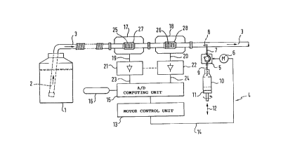
The milk-delivery arrangement shown in Figure 1 comprises a tank (1)
with milk supplied by the supplier and a means for suctioning milk as well as for
taking a sample e.g. provided at a milk collection truck, a container (not shown)
on the milk collection truck for taking over the milk from tank (1).
The manifold (2) of a delivery pipe line (3) projects into the tank (1)
and the opposite end of the manifold is connected to the storage tank or tanks
of the milk collection truck. A sampling means (4) which is designed for
representative milk sampling and comprises a tube pump (5), which is driven via
an electric motor (6), is connected for transmission with the intake of the delivery
Iine (3). The pump (5) is connected at its intake end via a pipe line (7) to an
intake cannula (8), which projects into the delivery line (3). At the opposite end
of the pump (5), a tube line (9) ends in a sampling tank (10). The tank (10) is
arranged on a carrier (11), which can be moved upwards and downwards in the
direction of the double arrow (12) in order to position a sampling bottle (10)
opposite to the line (9), i.e. to lower the bottle (10) out of this position and to
hand it over to a delivery means not shown. With the delivery means, both the
filled sampling bottle and a new sampling bottle are delivered. The sampling
bottles are preferably hermetically sealed by means of a plug. At its free end, the
tube line (9) has a stationary needle, which may penetrate the plug when the
carrier (11) is lifted. In order to support this process, the bottle (10) is fixed on
the carrier (11) and the carrier (11) rotates both during its upwards and its
downwards movement so as to facilitate the penetration process of the needle
or the pulling off of the bottle with the plug from the needle, respectively.
,.~ g
The pump (5) of the sampling means (4) is controlled as a function of
the momentary actual volume of milk delivered. Therefore, a control means (13)
is provided, which is connected to the motor (6) of pump (5) via a control line
(14). At its input side the motor control means (13) is connected to an arithmetic
5 and logical unit (15), which forms part of a data acquisition unit, by way of which,
among other things, the data of the supplier as well as desired data concerning
the milk charge can be input via an input means, such as e.g. via a keyboard
(16). Apart from that, signals from sensors (17), (18) are transmitted to the
arithmetic and logical unit (15), the sensors being installed in the delivery line (3).
10 The output signals from the sensors are processed via lines (19), (20) in circuits
(21), (22) before being transmitted via lines (23), (24) to the arithmetic and logical
unit (15), which at its input side additionally comprises analog/digital converters
for converting the processed analog sensor signals into digital signals.
The sensors subsequently arranged in the line (3) are a sensor (17)
15 for detecting the delivery rate, which is preferably constructed as magnetic-inductive flow meter (MID), and a sensor (18) for detecting the filling degree in
the delivery line (3), which is constructed as a conductivity sensor (G-sensor).It is beneficial for the precision of the detected delivery rate and the detected
filling degree that both sensors are constructed without mechanical detecting
20 organs. The sensors (17), (18) are basically arranged such that they do not
project into the flow and thus do not impair the flow concerning turbulences or the
like. In particular, the sensors (17), (18) do not have movable sensing organs.
Further, it is essential for precision in the data acquisition that both
sensors (17), (18) have planar electrodes (25), (26) for measured-value detection,
25 which are arranged in a rectangular or square chamber, (27 and/or 28) of the
sensor casing or in or at the faces of a rectangular cross-section of suction line
(3).
Thus, the sensors (17), (18) precisely and continuously detect the milk
flow and the filling degree as well as the filling level in the line (3), wherein these
30 measured values are linked with each other in order to represent the momentary
actual volume of milk delivered, after having passed the signal processing steps(21), (22) in the arithmetic and logical unit (15). As a function of the detected
- 10-
.~
.J 4 c~
momentary actual volume of the milk delivered, the controlling of the motor (6)
for the pump (5) takes place via the motor control (13) while taking into account
the data of the supplier and the desired data concerning the milk charge such
that a representative milk sampling is obtained. In doing so, it is of special
5 importance to take the milk sample exclusively as a function of the delivered
actual volume of milk so that, for example, the air contained in the milk cannotinfluence the sampling in an unfavourable manner. Dependencies on
disturbances, such as air contained in the milk or a flow in the vicinity of a wall,
which leads to incorrect measuring results in a filling-level measurement, are
10 consequently eliminated. In an alternative arrangement shown in Figures 3 and4 are provided a MID (37) as flow meter and a conductivity sensor (38) for
detecting the filling degree in a common casing (30). Rectangular electrodes
(35), (36), which are virtually identically constructed, are used as planar sensing
organs. In a slightly tapered area of the delivery line (3) the electrodes (35) and
(36), which are each arranged in parallel, of both sensors (37 and (38) are
positioned in such a manner that almost the entire pipe cross-section is detected
during measurements. Sensors (37) and (38) also permit the detection of the
filling level in the delivery line (3). For additional safety in the preferably
automatic calibration routine are also provided additional electrodes (39), (40)20 with a relatively small surface in an upper and lower centrical arrangement in the
almost square measuring chamber (34). Electrodes (39) and (40) particularly
supply data concerning the bottom covering and a flow over the entire cross-
section of the line. In this embodiment the electrodes (36) of the conductibility
sensor (38) for detecting the degree of filling are arranged in flow direction
25 upstream of the MID (37).
Figure 5 shows a velocity diagram of the milk delivered in the delivery
line, the delivery being subsequently performed from two tanks (1). In Figure 5,the time axis runs along the abscissa from right to left, and the first pulse train
corresponds to the velocity diagram of the milk delivery from the first tank, and
30 the second pulse train to the velocity diagram of the delivery from the second
tank.
-11 -
It becomes clear that, at first, the suction volume rises steeply and
becomes flatter during the course of the delivery. Incisions in the delivery
volume, which are detected by the filling degree sensor, indicate the presence of
air in the milk.
As is obvious from Figure 1, the end portion of the cannula (8) runs
inclined opposite to the milk delivery direction. The cannula portion ends with its
opening spaced from the bottom of the line (3). Said squaring off of the removalcannula (8) guarantees that even at the relatively lowest level of the sucked milk
in the pipe a sample can be taken. On the other hand, the suction cannula is
positioned with its opening so high above the lowest dead point of the pipe thataccount is not being taken of the residual milk in the line (3) of a previous
supplier for the representative sample of the following supplier. Apart from that,
as a result of the particularly inclined arrangement of the cannula (8) and the
large-surfaced construction of the electrodes of the sensors for detecting the
delivery rate and the degree of filling it is achieved that also very fat or creamy
milk can be detected representatively.
~1~
~ - 12-