Note: Descriptions are shown in the official language in which they were submitted.
2~2~~~Q
S P E C I F I C A T I O N
TITLE OF THE INVENTION
Multipurpose Bucket Structure
BACKGROUND OF THE INVENTION
Field of the Invention
The present invention relates to a multipurpose
bucket structure to be attached to the leading end
portion of an arm of a constructing machine such as a
power shovel.
Description of the Related Art
In the prior art, a working machine such as the
constructing machine or the power shovel can be used
according to its function for constructing works such
as a trench digging operation. Because of this
simplified function, the machine cannot be suffi-
ciently applied to various constructing works.
For example, the power shovel of the prior art
has a single bucket which is attached to the leading
end portion of its arm but which is not equipped with
any cover. Some power shovel is so modified as to
have various attachments. In either case, the func-
tions are so restricted that the working efficiency
1
X122890
cannot be enhanced to meet the term of works.
SUMMARY OF THE INVENTION
Therefore, the present invention is intended to provide
a multipurpose bucket structure suitable for tasks such as
carrying long materials; demolishing a building and taking
away the pieces; disassembling an automobile and taking away
the parts; working with a large-sized tool; digging the
ground; restoring an area destroyed by a disaster; carrying
ready-mixed concrete; and carrying concrete blocks or
secondary products of concrete.
Specifically, according to the present invention, there
is provided a multipurpose bucket structure comprising: a
body bucket forming an upper bucket jaw, said body bucket
having a first leading end portion and first peripheral edges;
and an openable bucket forming a lower jaw, said openable
bucket having a second leading end portion and second
peripheral edges; wherein said openable bucket is hinged to
said body bucket such that said body bucket and said openable
bucket are openable and closeable relative to each other;
wherein a gap is formed between said first peripheral edges
and said second peripheral edges when said body bucket and
said openable bucket are closed relative to each other; and
wherein said gap is closed by a cover removably attached to
at least one of said body bucket and said openable bucket
when said body bucket and said openable bucket are closed
relative to each other.
2
28827-1
X122890
The invention also provides a multipurpose bucket
structure comprising: a body bucket forming an upper bucket
jaw, said body bucket including a top portion and a first
leading end portion; and an openable bucket forming a lower
jaw, said openable bucket having a second leading end portion;
wherein said openable bucket is hinged to said body bucket
such that said body bucket and said openable bucket are open-
able and closeable relative to each other, said leading end
portions being in engagement with each other when said body
bucket and said openable bucket are closed relative to each
other; and wherein said top portion of said body bucket has a
pouring opening therein for pouring fluid cement mortar
therefrom for construction.
The invention further provides a multipurpose bucket
structure comprising: a body bucket comprising an upper base
portion and forming an upper bucket jaw fixed with said upper
base portion, said body bucket including a first leading end
portion; and an openable bucket forming a lower jaw, said
openable bucket having a second leading end portion; wherein
said openable bucket is hinged to said body bucket such that
said body bucket and said openable bucket are openable and
closeable relative to each other in a first plane, said leading
end portions being in engagement with each other when said
body bucket and said openable bucket are closed relative to
each other; and wherein said body bucket has a swivel
mechanism directly connected to said upper base portion
thereof, said swivel mechanism comprising means for swivelling
3
28827-1
~1~2890
said body bucket in a second plane perpendicular to said first
plane 360 degrees; and wherein said upper base portion further
comprises a plurality of lock holes and said swivel mechanism
further comprises a lock pin for locking said body bucket in
a swivelled positioned by engaging one of said lock holes of
said upper base portion; wherein said swivel mechanism further
comprises an oil pressure circuit leading to said swivelling
hydraulic motor and a swivel lock mechanism in said oil
pressure circuit; and wherein said swivel mechanism comprises
a lock cylinder for causing a locking motion of said locking
pin in accordance with the feed and interruption of working
oil to said swivelling hydraulic motor.
The invention still further provides a multipurpose bucket
structure comprising: a body bucket forming an upper bucket
jaw, said body bucket including a top portion fixed to and
above said upper bucket jaw and a first leading end portion;
an openable bucket forming a lower jaw, said openable bucket
having a second leading end portion; a horizontal mounting
plate connected to said top portion of said body bucket;
wherein said openable bucket is hinged to said body bucket by
a hinge pin such that said body bucket and said openable
bucket are openable and closeable relative to each other,
said leading end portions being in engagement with each other
when said body bucket and said openable bucket are closed
relative to each other; and an actuating cylinder extending
horizontally above said top portion of said body bucket and
below said horizontal mounting plate, so as to be between said
4
28827-1
J
X122890
top portion and said mounting plate, said actuating cylinder
having a first hinged portion hinged to said body bucket and
a second hinged portion hinged to said openable bucket, a line
connecting said first and second hinged portions being
substantially horizontal. The buckets are so hinged to each
other that their leading end portions can be opened and
closed, and each of said buckets is formed on its opening
peripheral edge with one or more tooth portions. With this
construction, the bucket structure is enabled, with its open-
able bucket being opened, to dig like the prior art by its body
bucket and to carry long materials by grasping them between the
tooth portions of its leading end.
In one embodiment, the gap formed between the peripheral
edge of the opening of the body bucket and the peripheral edge
of the opening of the openable bucket is useful to grasp the
long materials more easily and is closed with a removable
cover. In this closed state, the inside defined by the closed
body and openable buckets is completely sealed up to carry a
fluid material such as cement mortar therein. Since the
bucket structure can carry the fluid materials such as cement
slurry, it is conceivable to use it to place the concrete
material in a form at the site for the foundation work.
According to the present invention, the pouring operation
of the cement can be facilitated by forming a pouring port in
the top portion of the body bucket.
The opening/closing actions of the aforementioned body
bucket and openable bucket can be effected by an actuating
cylinder, so that the supply of working oil to the actuating
4a
28827-1
X12 2s 9 0
cylinder can be remotely controlled from the body of the
working vehicle. In this modification, moreover, the actuating
cylinder is accommodated in a protecting box outside of the
body bucket, so that it can be protected against not only sand
or other members but also a collision.
Furthermore, the working oil passage to that actuating
cylinder is equipped in its midway with a lock valve for lock-
ing the actuating cylinder in a predetermined length, and the
lock valve is equipped with a decompression valve for
decompressing an abnormally high pressure, if applied to the
actuating cylinder, to release the locked state. Thus, it is
possible to prevent the lock valve, the openable bucket or
the body bucket from being broken when in an abnormal operation.
The pouring operation of the aforementioned cement slurry
can be facilitated as mentioned by forming the pouring port in
the top portion of the body bucket. The aforementioned bucket
structure composed of the body bucket and the openable bucket
can be swivelled with respect to the mounting portion of the
constructing machine. As a result, the body bucket can be
swivelled at an arbitrary angle so that the materials can be
easily folded or cut by turning the body bucket while grasping
the materials between the buckets.
Furthermore, the buckets may be formed to have at least
one of their
4b
28827-1
~12~~9U
back portions with a sloped flat wall portion to level
the placed concrete or the ground.
A more detailed construction of the present in-
vention and the effects obtained therefrom will become
apparent from the following description to be made
with reference to the accompanying drawings.
BRIEF DESCRIPTION OF THE DRAWINGS
Fig. 1 is a side elevation of a bucket structure
of the present invention and shows a body bucket and
an openable bucket in a vertical section;
Fig. 2 is a side elevation showing the bucket
structure of the present invention, in which the body
portion of the buckets is turnably attached;
Fig. 3 is a vertical section showing an essential
portion of the bucket structure of the present inven-
tion with its openable bucket being opened;
Fig. 4 is a side elevation showing the body
bucket;
Fig. 5 is a side elevation showing the openable
bucket;
Fig. 6 is a side elevation showing the state in
which the bucket structure of the present invention is
attached to the arm of a working vehicle through a
swivel mechanism;
_..ri.....__._.._....__.~ ___.__.___~_...~.__~., ~._._.
.e_ ~x~2$90
Fig. 7 is a side elevation showing the state in
which the bucket structure of the present invention is
attached to the arm of a working vehicle not through
the swivel mechanism;
Fig. 8 is a side elevation showing a bucket
structure according to anther embodiment of the pre-
sent invention; .
Fig. 9 is a top plan view showing the bucket
structure of Fig. 8;
Fig. 10 is a side elevation of an essential por-
tion and shows an actuating cylinder accommodating box
portion of the bucket structure of Fig. 1 in a verti-
cal section;
Fig. 11 is a top plan view showing the actuating
cylinder accommodating portion of Fig. 10 in a hori-
zontal section;
Fig. 12 is a side elevation of a piping case;
Fig. 13 is a front elevation showing the piping
case;
Fig. 14 is a side elevation showing a retaining
hook to be attached to a side of the body bucket;
Fig. 15 is a side elevation showing a bucket
structure according still another embodiment of the
present invention;
Fig. 16 is a side elevation showing a modifica-
6
m_ 2122890
tion of the bucket structure of Fig. 15;
Fig. 17 is a longitudinal section showing a
swivel locking mechanism;
Fig. 18 is a longitudinal section showing the en-
tirety of a lock valve with a decompression mechanism;
and
Fig. 19 is an enlarged section showing an essen-
tial portion of Fig. 18.
DESCRIPTION OF THE PREFERRED EMBODIMENTS
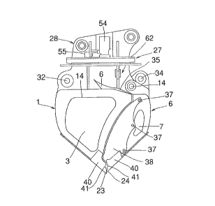
In Fig. 1, reference numeral 1 designates a body
bucket which is constructed of a back portion 2,
righthand and lefthand side portions 3 and a top por-
tion 4. The body bucket 1 is opened at 5 at its front
portion opposed to the back portion 2. On the other
hand, numeral 6 designates an openable bucket, which
is also constructed of a back portion 7, righthand and
lefthand side portions 8 and a top portion 9 and open-
ed at 10 at its front portion. These body bucket and
openable bucket 1 and 6 are protruded from their re-
spective top portions 4 and 9 to form base portions 12
and 13. To the base portion 12 of the body bucket 1
in the vicinity of the opening 5, there is hinged by
means of a pin 14 the base portion 13 of the openable
bucket 6 so that the openable portion 6 can be turned
7
_ ____-~..-..,~."
_ ____._...~_ __-. __ .
_. _ _~._.
_r 2 i
and opened on the hinge pin 14.
The body bucket 1 is formed, at the upper end
portions of the side portions 3 in the peripheral
edges of the opening 5, with a semicircularly recessed
back tooth portion 16, which is so faced by a semicir-
cularly recessed back tooth portion 17 formed in the
side portions 8 of the openable bucket 6 that the two ,
back tooth portions 16 and 17 can mesh with each
other. Moreover, the openable bucket 6 is formed with
a higher tooth portion 18 which is farther projected
than the back tooth portion 17 to come into the open-
ing 5 inside of the side portions 3 of the body bucket
1. Still moreover, the peripheral edges of the open-
ing 5 below the individual back tooth portions 16 and
17 are individually gently recessed to establish a gap
20 between the side portions 3 and 8 of the body
bucket 1 and the openable bucket 6. Furthermore, the
side portions 3 and 8 are formed at their lower end
portion below the gap 20 with projecting middle tooth
portions 21 and 22, and the back portions 2 and 7 are
formed at their leading end portions with front tooth
portions 23 and 24 between the side portions 3 and 8.
The back portions 2 and 7 are inclined below
their vertically intermediate portions toward the
front tooth portions 23 and 24 to form flat plate por-
8
_ ___ .._
__._.. __ .r____
tions 25 and 26 so that the two buckets 1 and 6 have
the slopes at the lower portions of their back por-
tions.
On the other hand, the upper base portion 12 of
the body bucket 1 is composed of two righthand and
lefthand side plates 30, between which is so horizon-
tally arranged a hydraulic cylinder 31 as is directed
generally in parallel with the opening/closing direc-
tions. This hydraulic cylinder 31 has its bottom
hinged to the portion ,just above the back portion 2 of
the body bucket 1 at the side opposed to the hinge pin
14 of the openable bucket 6 by means of a hinge pin 32
fitted between the two side plates 30. The opposite
rod 33 of the hydraulic cylinder 31 has its leading
end hinged to the base portion 13 of the openable
bucket 6 through a ,joint pin 34 positioned above the
aforementioned pin 14. Thus, the openable bucket 6
has its leading end turned downward to take a closed
position, as shown in Fig. 1, when the hydraulic cyl-
finder 31 has its rod 33 extended, but takes an open
position when the rod 33 is contracted.
In Fig. 2, to the upper portion of the base por-
tion 12 at the upper end of the body bucket 1, there
is attached through a swivel mechanism 27 a mounting
base 28 for a working vehicle. Specifically, this
9
,_
mounting base 28 is attached to the leading end of the
arm 29 of the working vehicle, as shown in Fig. 6, so
that a bucket structure composed of the body bucket 1
and the openable bucket 6 can be swiveled by 360 de-
grees with respect to that arm 29. Incidentally, Fig.
7 shows the case in which the bucket structure is at-
tacked to the arm 29 not~through the aforementioned
swivel mechanism 27.
Figs. 8 to 14 show another embodiment of the
present invention. First of all, the body bucket 1 is
formed in the upper face of its top portion 4 with a
pouring port 35 for pouring a fluid material for con-
structions such as cement milk. This pouring port 35
is surrounded by a funnel portion 36 which has a slop-
ed upper face. Moreover, the aforementioned gap 20
between the side portions 3 and 8 of the body bucket 1
and the openable bucket 6 is closed by a cover plate
38 which is removably fastened to the side portions 8
in the vicinity of the opening of the openable bucket
6 by means of bolts 37, 37 and 37. While the openable
bucket 6 is being closed, the cover plate 38 has i_ts
leading end abutting closely against the end portion
of the side portions 3 of the body bucket 1. As a
result, the fluid material is prevented from overflow-
ing from the gap 20 when it is poured from the afore-
_w.~_ ._._.~~_._~._.~_..~....~..,.~..~........-_ . .
mentioned pouring port 35 or scooped up.
In the bucket structure of this embodiment, more-
over, there are added edge members 40 and 40 for form-
ing the aforementioned front tooth portions 23 and 24
of Fig. 1. The edge members 40 and 40 are formed
above the front tooth portion 20 with slightly reces-
sed portions 41 and 41.
As shown in Figs. 10 and 11, the pin 32 support-
ing the bottom side of the hydraulic cylinder 31 is
inserted into a pin bearing hole 44which is formed in
a joint portion 43 integrally formed across the side
plates 30 and 30. The joint portion 43 is constructed
to plug the bottom-side opening of the hydraulic cyl-
finder 31 to prevent invasion of sand as much as pos-
sable. To the upper end portion of the side plates
30, moreover, there is so attached a horizontal mount-
ing plate 45 as to close the open portion between the
side plates 30 and 30. Thus, the side plates 30 and
30, the joint portion 43 and the mounting plate 45
constitute altogether a box for protecting the hydrau-
lic cylinder 31.
Above the cylinder portion of the hydraulic cyl-
finder 31, there is mounted a lock valve 46 which is
equipped with a decompression mechanism for holding
the hydraulic cylinder 31 at a predetermined exten-
11
2122890
sion. Numeral 48 designates an oil pressure piping to
the hydraulic cylinder 31. This hydraulic cylinder 31
can be used for various works by replacing the open-
able bucket by another attachment.
The aforementioned mounting plate 45 has a round
shape, as seen from a top plan view of Fig. 9, and is
formed along its outer circumference with a number
lock holes 50. To the swivel portion of the aforemen-
tinned swivel mechanism 27, there is accordingly at-
tacked a lock cylinder 51 which can have its rod in-
serted into one of the lock holes 50 to lock the
aforementioned bucket structure in a horizontally
swiveled arbitrary position. Numeral 52 designates a
relief valve which is disposed midway of an oil pres-
sure piping 53 to that lock cylinder 51.
In Fig. 8, numeral 55 designates a piping case
disposed in one portion of the aforementioned mounting
base 28. This piping case 55 is equipped with oil
passages 56 for a swiveling hydraulic motor and oil
passages 57 for a hydraulic cylinder, as shown in
Figs. 12 and 13. The oil passages 56 have their one
port 58 connected with the piping of the lock cylinder
51 and their other port 59 connected with the piping
of the hydraulic motor. This swiveling hydraulic
motor 54 is mounted on the swivel mechanism 27, as
12
.... _ _..__-._._-......-.~~...~~..... ....._._ _.~ _ _. ~.-._..._.._.. _
,.. __....~. _... _ _
~1~2$90
shown in Fig. 8, to drive the same for the swiveling
motions. The cylinder oil passage 57 has its one port
60 connected with one chamber of the hydraulic cyl-
finder 31 through a not-shown rotary ,joint and its
other port 61 connected with the not-shown piping of
the hydraulic pump.
Fig. 14 shows a side of a retaining portion for a
suspension hook, which is attached to the outer face
of one base portion 12 above the body bucket 1. This
suspension hook retaining portion 62 is composed of a
groove 63 for inserting a hook and a lock lever 64
made turnable to close one portion of the groove 63.
The retaining portion 62 thus composed has its lock
lever 64 turned outward and prevented from coming out
when the hook or the like is fitted in the groove 63.
Figs. 15 and 16 show a bucket structure according
to another embodiment. In this embodiment, the re-
spective side portions of the body bucket 1 and the
openable bucket 6 are formed with the middle tooth
portions 21 and 22, one of which is recessed whereas
the other of which is projected. As shown in Fig. 16,
the edge members 40 and 40 are attached for forming
those middle tooth portions 21 and 22. Moreover, the
body bucket 1 and the openable bucket 6 of Fig. 16 are
not formed with the sloped side portions but have
13
__
~.~228.~a
their back portions bulging outward.
Fig. 17 shows the aforementioned swivel locking
mechanism in detail. On the outer circumference o-P
the mounting base 28, there is mounted a cylindrical
lock pin guide 70, into which is vertically movably
inserted a lock pin 71. 'This lock pin 71 has its
lower end inserted into one of the lock holes 50 o-f
the aforementioned mounting pJ.ate 45, to lock the
swiveling motion of the mounting plate 45. 'the lock
pin guide 71 has its internal diameter enlarged at its
upper end. Into this enlarged portion, there is in-
serted the lower end of the aforementioned lock cyl-
finder 51. 'this lock cylinder 51 has its internal
diameter gradually reduced at an upward first step
portion 72 and an upward second step portion 73 posi-
tinned below the former. lnto this lock cylinder 51,
there i.s inserted a first piston 74 which is Porrned on
its outer circumference with such downward step por-
tions 85 and q2 for abutting against the aforemen-
tinned step portions 72 and 73. The first piston 74
has a cylindrical shape having a bottom portion 75 at
its lower end. Diametrically through the first piston
74, there is so inserted a pin-push pin 76 as to abut
against the inner face of the bottom portion 75. This
pin-push pin 76 has its two ends extending through a
14
_ 212280
vertically long bore 90, which is formed in the cir-
cumferential wall of the first piston 74, and fixed by
the aforementioned lock pin 71. Into the first piston
74, moreover, there is so inserted downward a rod-
shaped second piston 77 as to have its lower end abut-
tang against the aforementioned pin-push pin 76. A
flange 78 formed on the~outer circumference of the
cylinder 51 is fixed on the aforementioned mounting
base 28 by means of bolts 79 inserted downward. These
bolts 79 have their leading ends driven into a support
member 80 positioned below the mounting base 28. The
lock cylinder 51 has its upper end opening closed by a
spring seat 49. Moreover, a first spring 86 is mount-
ed between the back of the spring seat 49 and an in-
ward step portion 87 of the aforementioned first pis-
ton 74, and a second spring 89 is mounted between the
back of the spring seat 49 and a spring receiving step
portion on the outer circumference of the second pis-
ton 77.
At the same time, the lock cylinder 51 is formed
in its outer circumference with inlet ports 81 and 82
for feeding working oil to the upper portions of the
aforementioned first and second step portions 72 and
73, and outlet ports 83 and 84 above and for those in-
let ports 81 and 82. Specifically, when the working
2122$90
fluid is fed from the inlet ports 81 and 82, its pres-
sure acts upon the individual step portions 85 and 86
of the first piston 74 to lift the first piston 74
against the force of the first spring 86. As the
first pin 74 rises, the lock pin 71 is pulled upward
through the pin-push pin 76 to release the locked
state. Simultaneously with this, the second piston 77
is also lifted against the force of the second spring
89. When the first piston 74 rises to a predetermined
position, the inlet ports 81 and 82 acquire communica-
tion with the outlet ports 83 and 84, respectively, so
that the working oil is fed from the outlet ports 83
and 84 to the aforementioned swivel cylinder. When
the feed of the working oil is interrupted, the swiv-
eling motion is also interrupted so that the first
piston 74 is pushed back by the individual forces of
the springs 86 and 89 to bring the lock pin 71 into
one of the lock holes 50 to effect the swivel lock.
At this time, the first piston 74 can move downward
ahead of the second piston 77 within a range of the
long bore 90 so that a quick locking action can be
achieved. Thus, the swivel mechanism is automatically
locked and unlocked in accordance with the feed and
interruption of the working oil to the swivel motor.
Incidentally, numeral 91 designates a bearing for
16
_ _ ...__.___._ .__.__.._ ~..,_.-
~_.m._..~,._"_.~,.~~....~....~.,.....~.._.,~.~m...~...-
._..~~_..._...._.~...,.~~.._._
X122890
guiding the turning motion of the mounting plate 45.
Figs. 18 and 19 show a structlirc of the lock
valve 46 with a decompression mechanism for locking
the aforementioned hydraulic cylinder 31.
At the center in a valve fitting bore 101 extend-
ing through a valve cylinder 100 to the right and left
of Figs. 18 and 19, there is slidably fitted a main
piston 103 which is formed with projections at its two
ends. The valve fitting bore 101 has its two end
openings closed with bolts 105 fastened therein. Into
a threaded hole 106 at the leading end of each mount-
ing bolt 105, there is driven one end of a cylindrical
casing 107 so that the main piston 103 is fitted in
the aforementioned bore 101. The casing 107 is radi-
ally reduced at the end opposed to the bolt 105. Into
the inside of the reduced portion 108, there is fitted
a valve body 109 which has its outer circumference
tapered at its intermediate portion. The casing 107
is formed in a position corresponding to the outer
circumference of the valve body 109 with a communica-
tion hole 110 for providing communication between the
inside and outside of the casing 107. On the other
hand, the taper portion has its outer circumference
111 abutting against a valve seat 112 at the inner end
of the reduced portion 108 of the casing 107 to break
17
.. . .__.__...__-.. ___._____.._.._~
_...~v_._..~ ~...
~~r.._ __.........__~w.~._...
~i~~s~a
the communication between the aforementioned com-
munication hole 110 and oil pressure chambers 113 and
114 at the two sides of the main piston 103.
Into a through hole 116 formed longitudinally of
the valve body 109, there is fitted a smaller piston
115 which has its outer circumference formed into two
larger and smaller portions across a longitudinally
taper portion 120. The smaller piston 115 has its
smaller portion 121 protruded from the leading end of
the valve body 109. On the other hand, the valve body
109 has its through hole 116 formed into two larger
and smaller portions corresponding to the external
diameters of the smaller piston 115, to leave small
clearances 118 and 119 between itself and the smaller
piston 115. The aforementioned taper portion 120 is
held in abutment against a valve seat 123 at the inner
end of the smaller portion. The valve body 109 is
formed with a communication hole 124 for providing
communication between the aforementioned communication
hole 110 and the clearance 118 around the outer cir-
cumference of the larger portion of the smaller piston
115. Between a spring fitting hole 125 formed in the
bottom of the threaded hole 106 of the mounting bolt
105 and the inner end of the smaller piston 115, more-
over, there is mounted a spring 126 for pushing the
18
taper portion 120 of the smaller piston 115 to the
aforementioned valve seat 123.
The valve cylinder 100 is formed with two inlet
passages 128 and 129 which are connected to the afore-
mentioned oil pressure chambers 113 and 114, respec-
tively, for introducing the working oil from the work-
ing oil pump into the oil pressure chambers 113 and
114. The valve cylinder 100 is further formed with a
pair of outlet passages 130 and 131 which are con-
netted with the communication hole 110 of the afore-
mentioned casing 107 for introducing the working oil
from the communication hole 110 to the bottom and rod
of the aforementioned hydraulic cylinder 31. Of
these, one outlet passage 130 communicating with the
lefthand oil pressure chamber 114 is bypassed in a
hook shape to communicate with the outside through an
outlet port 132 which is formed in the back at the
center of the main piston 103.
In the construction thus made, one inlet passage
129 is used for feeding the working oil to the bottom
side of the hydraulic cylinder 31, whereas the other
inlet passage 128 is used for feeding the working oil
to the rod side of the same. Thus, the working oil
enters, when fed from its pump to the inlet passage
129 at the bottom side, to the corresponding oil pres-
19
. . ~ . .... .......... ..__.__._ _.__._..__-..... ~~w...
..r.___ __..__..._..... __ _ _.
X122890
sure chamber 114. The pressure of the working oil
thus fed to the oil pressure chamber 114 slides the
main piston 103 to the left of the drawings so that
the projection 102 at the leading Pnd of the main pis-
ton 103 pushes and moves the smaller piston 103, as
shown in Fig. 19, to the left of the drawings. As a
result, the taper portion 120 leaves the valve seat
123 of the valve body 109 so that the outlet passage
130 comes into communication with the oil pressure
chamber 113 through the clearances 118 and 119 around
the outer circumference of the smaller piston 115 and
through the communication holes 124 and 110. As a
result, the working oil at the rod side is relieved to
the drain side to release the pressure of the rod side
chamber gradually.
Next, the valve body 109 is pushed and moved in
the same direction by the main piston 103 so that it
leaves the valve seat 123 of the casing 107 to drain
out the working oil of the rod side chamber substan-
tially. Thus, the substantial release of the working
oil is not carried out before the working oil in the
bottom side chamber or the rod side chamber is slight-
ly returned to the drain side. As a result, there can
be achieved an advantage that the openable bucket does
not start its opening/closing action abruptly but has
2122890
its operation simplified.
On the other hand, the working oil having entered
the oil pressure chamber 114 at the bottom side slides
the valve body 109 at the bottom side to the right of
the drawings so that the communication between the in-
let passage 129 and the outlet passage 131 is estab-
lashed through the communication hole 110 to feed the
working oil to the bottom side of the hydraulic cyl-
finder 31. As a result, the hydraulic cylinder 31 is
extended while discharging the working oil of the rod
side by the pressure at the bottom side thereby to
open the aforementioned openable bucket 6. In a neu-
tral state in which the working oil is fed to neither
of the inlet passage 128 and 129, moreover, the valve
body 109 is held in the original position by the force
of the spring 126 so that any passage is shut out to
lock the openable bucket 6 in its open state.
Although the present invention has been described
hereinbefore in connection with its preferred embodi-
ments, it can be modified in various manners within
the scope of the appended claims. It should be noted
that the present invention should not preclude those
modifications.
21
_. ___....~~
~_..ru~....~. _. _...