Note: Descriptions are shown in the official language in which they were submitted.
- 21 22~32 PATENT
PD-W2028
RUGATE FlLrER RAVI~G SUPPRESSED ~ARMONICS
BACKGRO~1) OF T~ IVF~ON
The present invention generally relates to rugate filters and, in particular, relat~s
to one such rugate filter having ~.Jppl~d barrnonics.
Con~c~nal optical filters are usually fabricated by applying a plulality of
discrete layers of material to an optical s~sllate. The material of each of the layers is
s~l~cted so that there is a change in the inde~ of refraction at every intc~Ça~. More
specifically, the m~teri~l of the layers is chosen so that the inde~c of refraction alt~l,-at s
from a cG."p~tively higha (or lower) value to a comparatively lower (or higher) value
at each layer inte~C~
As known in the field of optics, when light impinges upon any interfaoe whae
there is a difrerence in the inde~ of refraction some of the incident light will be refl~t~
Further, at an interface whereat the incident light traverses from a material of relatively
high inde~ of refraction to a material of relatively low inde~c of refraction a phase change
of 180degreesisintroducedintothereflectedlight. Henoe, thereis, withtheapprop,iate
choice of layer thickness, destructive c~n~ tion of the reflected light at consecutive
interfaces. Consequently, the more interfaces an incident light beam traverses, the
greater the amount of the ir~cident light reflected and canceled. When subs~nti~lly all of
the light of a particular wavelength is reflected and c~ncel~d before reaching the optical
substrate, that wavelength of light can be said to have been filtered, or rejected, from the
incident light bearn. It is known and understood that, with such stacke~d arrangements1
not only is the principle wavelength rejected but the harrnonics thereof are also rejected.
More recently, rugate filters have been developed. In the case of rugates, rather
than forming a plurality of discrete layers of material onto an optical substrate, a single
layer of material is forrned in such a fashion that the inde~c of refraction varies within the
layer itself. Typically, such rugates are effected by a continuous deposition process
during which one or more of the materials deposited are varied. Hence, the variation of
~' 1 22q32
in index of refraction.
In one particular application, i.e., single
wavelength rejection filters, the typical rugate will
have an index of refraction versus optical thickness
profile through the layer that is sinusoidal. As used
herein the term "optical thickness" is taken to mean the
product of the mechanical thickness and the index of
refraction. However, other profiles can be implemented
depending upon the optical characteristics desired. In
general, multiple reflection bands can be generated by
superimposing the individual refractive index profiles
and depositing the resulting profile. For example, if a
number of wavelengths are to be suppressed, the profile
of the final rugate would be the resultant profile of the
sum of the individual profiles desired.
One of the advantages of rugates is that the
resultant layer is quite thin. In fact, the typical
rugate layer is sufficiently thin that incident light ray
deviations due to changes in the index of refraction is
negligible.
While a sinusoidal rugate exhibits some harmonic
suppression compared to comparable stacked single
wavelength rejection filters, the harmonic content
remains significant. In fact, it has been found that the
conventional superimposing of the individual refractive
index profiles does not seem to apply with respect to the
rejection of the harmonics of the principle wavelength.
The rejection of harmonics is an important
consideration regardless of the intended use of the
rugate filter, however, it becomes extremely important
when the rugate is used to reject laser light of known
wavelengths. The rejection of laser light is important
for both domestic and military applications.
- 2 -
~' .
.
2 ~ 22932
-
The problem of suppressing harmonics in rugates has
been given much consideration in the art. For example,
one approach has been to superimpose an elliptical
function with the principle sinusoidal filter function.
Such an approach is discussed in an article by W. H.
Southwell, entitled "Rugate Index Profile Which
Suppresses All Harmonic Stopbands", 1988 Technical Digest
Series, Vol. 6. However, this approach does not correct
for what seem to be manufacturing anomalies that appear
to be inherent in many rugate manufacturing processes.
For example, it is not unusual to find strong harmonics
even when the various corrective techniques have been
implemented.
Consequently, a rugate filter having suppressed
harmonics is clearly desirable and needed.
SUMMARY OF THE lNv~NlION
Accordingly, it is an object of an aspect of the
present invention to provide a rugate filter that
substantially completely overcomes the drawbacks of
present rugate filters discussed above.
This object is accomplished, at least in part, by
providing a rugate filter having an index of refraction
versus optical thickness profile that effectively
suppresses harmonics of the principle wavelength for
which the filter is designed.
Another aspect of this invention is as follows:
A rugate filter having suppressed harmonics
comprising: an optical substrate having a surface; and a
layer of material on said surface, said layer having an
index of refraction versus optical thickness profile that
varies according to the superimposing of a principle
sinusoid for rejection of a principle wavelength of
optical radiation and a secondary sinusoid having an
- 3 -
21 22~32
index of refraction versus optical thickness profile
having an amplitude of about 10% of that of said
principle sinusoid, and a phase difference of about -90
with respect to said principle sinusoid whereby filter
harmonics of the principle wavelength are suppressed.
Other objects and advantages will become apparent to
those skilled in the art from the following detailed
description read in conjunction with the appended claims
and the drawings attached hereto.
BRIEF DESCRIPTION OF THE DRAWINGS
The drawings, not drawn to scale, include:
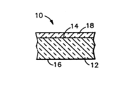
Figure 1 which is a cross-sectional view of a rugate
filter having suppressed harmonics and embodying the
principles of the present invention;
Figure 2 which is an index of refraction versus
optical thickness profile for the principle sinusoid of
the rugate filter shown in Figure 1;
Figure 3 which is an index of refraction versus
optical thickness profile for the secondary sinusoid of
the rugate filter shown in Figure 1;
Figure 4 which is an index of refraction versus
optical thickness profile of the superposed profile of
the rugate filter shown in Figure 1;
Figure 5 which is an index of refraction versus
optical thickness profile of a single cycle comparing the
principle sinusoid with the superposed sinusoid; and
Figure 6 which is an index of refraction versus
optical thickness profile for a tertiary sinusoid for use
with the rugate filter shown in Figure 1.
DETAILED DESCRIPTION OF THE lNv~NlION
A rugate filter, generally indicated at 10 in Figure -
1 and embodying the principles of the present invention,
includes an optically transparent substrate 12 having
- 4 -
.
2 1 22~32
first and second opposing surfaces, 14 and 16,
respectively, and a layer 18 deposited on one of the
surfaces, 14 or 16, of the optically transparent
substrate 12. The layer 18 has an index of refraction
versus optical thickness profile equal to the super-
position of at least a principle sinusoidal index of
refraction versus optical thickness profile and a
secondary sinusoidal index of refraction versus optical
thickness profile, the secondary index of refraction
versus optical thickness profile being related to the
principle sinusoid in amplitude, period and phase. In
the preferred embodiment, the amplitude of the secondary
profile is about 10% of the amplitude of the principle
sinusoid, the period of the secondary profile being about
one-half the wavelength of the principle, and the phase
of the secondary profile being -90 degrees with respect
to the principle sinusoid.
As shown in Figure 2, in one particular embodiment,
the principle sinusoidal variation is designed to reject
light having a reflection band centered at a wavelength
of around 2 micrometers. For such an embodiment, the
index of refraction versus optical thickness profile of
the principle sinusoid is provided with about 30 full
cycles to ensure that the principles wavelength is
substantially completely rejected. Such a profile
results in the layer 18 having a finished mechanical
thickness of about 15 micrometers. In this particular
embodiment, the principle sinusoid has an amplitude of
about 0.1, that is, the index of refraction varies plus
or minus 0.1 from the center index of refraction, which,
in the embodiment shown in Figure 2 is equal to 2. The
principle sinusoid has a period of about 1 micrometer.
- 5 -
.._~
2 i 2~932
The index of refraction versus optical thickness profile
shown in Figure 2, nonetheless, as discussed above,
does not effectively suppress the harmonics of the
principle wavelengths. That is, sufficient light at the
second and third harmonics, i.e., at wavelengths of about
1.0 micrometers and 0.5 micrometers, respectively, is
still not transmitted through the optical substrate 12 to
render such a filter ineffective for many purposes.
The secondary sinusoidal index of refraction versus
optical thickness profile for the filter 10 of this
specific embodiment is shown in Figure 3. As shown
therein, the secondary sinusoid has an amplitude on the
order of about 10~ of the amplitude of the principle
sinusoid, in this embodiment, about 0.01. The period of
the secondary sinusoid is about one quarter of the
wavelength of the principle. However, it has been found
that, for superimposition purposes, the secondary
sinusoid should be superimposed, not in phase, as is
considered conventional, but out of phase with the
principle sinusoid by about -90 degrees.
Hence, by superpositioning the principle sinusoidal
profile, shown in Figure 2, and the secondary sinusoidal
profile, shown in Figure 3, the index of refraction
versus optical thickness profile of the layer 18, shown
in Figure 4, is obtained. Although the superposed
profile shown in Figure 4 looks substantially identical
to that of the principle sinusoid shown in Figure 2,
subtle differences are, in fact, introduced by the
superpositioning of the profile shown in Figure 3. Such
differences can be more readily appreciated in the
profile shown in Figure 5. Therein, a single cycle of
the principle sinusoid (shown in dashed line) is compared
with a single cycle of the superposed sinusoid (shown in
a solid line).
-- 6
2~ 22932
It has been determined that by the use of such a
superpositioning profile both the second harmonic and the
third harmonic of the 2 micrometer principle wavelength
are significantly reduced. For example, in one
particular embodiment, the second harmonic, i.e., at
about the 1.0 micrometer wavelength, was reduced by about
95%. Further the third harmonic, i.e., at about the 0.5
micrometer wavelength has been reduced by about 90%.
Thus, the comparatively small changes produced by the
superpositioning described herein and clearly pointed out
in Figure 5, result in significantly suppressed
harmonics.
Nonetheless, in some instances, the third harmonic
may still be of sufficient magnitude that further
filtering is desired. In such an instance, the layer 18
may be provided with an index of refraction versus
optical thickness profile such as that shown in Figure 6.
Such a profile is then superimposed into the profile
shown in Figure 2 along with the profile for the
suppression of the second harmonic shown in Figure 3.
Such a tertiary sinusoid preferably has an amplitude
of about 1% of that of the principle sinusoid. The
period of the tertiary profile is about one-sixth of the
principle wavelength. The tertiary sinusoid is,
preferably, superimposed about -60% degrees out of phase
with respect to the principle sinusoid.
The filter 10 having suppressed harmonics can be
fabricated from materials and by methods known in the
rugate fabrication art.
Although the present invention has been discussed
with respect to one or more specific embodiments it will
be understood by those skilled in the art of rugates that
other arrangements and configurations can also be
- 7 -
, . . .
~' .
~' ~ 22~32
generated that do not exceed the spirit and scope hereof.
Hence, the present invention is deemed limited only by
the appended claims and the reasonable interpretation
thereof.
~S~
, .