Note: Descriptions are shown in the official language in which they were submitted.
2122941
PATENT
APPARATUS AND METHOD OF ASSEMBLING AN INNER TUBE INTO AN OUTER TUBE
FIELD OF THE INVENTION
5This invention relates to an apparatus and method of assembling
an inner tube into an outer tube to form a tampon applicator.
BACKGROUND OF THE INVENTION
Tampon applicators are used to assist a woman in positioning a
catamenial tampon into her vagina. Tampon applicators come in a
variety of shapes and configurations. Many tampon applicators
utilize two members telescopically assembled, wherein the first
member is designed to contain a tampon and the second member is
designed to expel the tampon from the first member. The first member
or outer tube usually consists of a hollow tubular barrel connected
to a smaller fingergrip portion having an opening formed
therethrough. The second member or inner tube can be in the form of
a solid stick or a hollow tube sized to slide within the opening
formed in the fingergrip portion. The inner tube is designed to
expel the tampon from the outer tube when pushed into the outer tube.
Essentially all tampon applicators sold today have a straight,
longitudinal central axis.
The apparatus and method of assembling an inner tube into the
outer tube is fairly simple when both members have a straight,
central axis. However, when both members have an arcuately shaped
longitudinal central axis or when the radius of curvature of each
longitudinal central axis is different, it becomes difficult to
assemble the two members. The assembly is further complicated when
the inner tube has an outer diameter which is just slightly less than
the size of the opening formed in the fingergrip portion of the outer
tube. Lastly, when the assembly is conducted at very fast line
2122941
speeds~ the task takes on enormous proportions. Up until now, no one
has had to assemble two arcuately shaped hollow tubes at very high
line speeds.
Now an apparatus and method have been developed which enables an
inner tube to be assembled into a hollow outer tube to form a tampon
applicator.
SUMMARY OF THE INVENTION
Briefly, this invention relates to an apparatus and method of
assembling an inner tube into a hollow outer tube to form a tampon
applicator. The apparatus includes a first member configured to mate
with the outer tube and a second member configured to mate with the
inner tube. A vacuum is intermittently supplied to the first and
second members to hold the inner and outer tubes in coaxial alignment
along an arcuate centerline. The apparatus also includes a push rod
which is designed to contact and move the inner tube off of the
second member and into the outer tube. The movement of the push rod
is controlled by a mechanism which can reciprocally move the push rod
a predetermined distance at a set time to permit the inner tube to be
inserted into the outer tube.
The method includes the sequential steps involved in using a
vacuum to position the inner and outer tubes in alignment to one
another and then using the push rod to insert the inner tube into the
outer tube.
The general object of this invention is to provide an apparatus
and a method for assembling an inner tube into an outer tube to form
a tampon applicator. A more specific object of this invention is to
provide an apparatus for inserting an arcuately shaped inner tube
into a hollow, arcuately shaped outer tube.
Another object of this invention is to provide an apparatus for
coaxially aligning a hollow, arcuately shaped inner tube into a
hollow, arcuately shaped outer tube.
A further object of this invention is to provide a quick and
efficient method of inserting an inner tube into a hollow outer tube
at very fast line speeds.
2122941
Still another object of this invention is to provide an
inexpensive method of inserting an inner tube into a hollow outer
tube.
Still further, an object of this invention is to provide an
apparatus and method which can assemble an inner tube into a hollow
outer tube at machine speeds in excess of 100 assemblies per minute.
Other objects and advantages of the present invention will
become more apparent to those skilled in the art in view of the
following description and the accompanying drawings.
BRIEF DESCRIPTION OF THE DRAWINGS
Fig. 1 is a side elevational view of a curved tampon applicator
for facilitating insertion of an absorbent tampon into a woman's
vagina.
Fig. 2 is a cross-sectional view of the curved tampon applicator
shown in Fig. 1 depicting the tampon contained in the barrel of the
outer tube.
Fig. 3 is a schematic diagram of an apparatus for assembling an
inner tube into a hollow outer tube.
Fig. 4 is a side elevational view of the first member holding
the outer tube in a vertical arrangement.
Fig. 5 is a right front view of the first member shown in
Fig. 4.
Fig. 6 is a top view of the first member shown in Fig. 4.
Fig. 7 is a cross-sectional view of the first member shown in
Fig. 4 taken along line 7--7.
Fig. 8 is a side elevational view of the second member holding
the inner tube in a vertical arrangement.
Fig. 9 is a bottom view of the second member shown in Fig. 8.
Fig. 10 is a flow diagram of the method of assembling an inner
tube into a hollow outer tube.
DETAILED DESCRIPTION OF THE PREFERRED EMBODIMENT
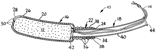
Referring to Figures 1 and 2, a curved tampon applicator 10 is
shown containing a catamenial tampon 12. The catamenial tampon 12
has a withdrawal string 14 attached to an end thereof. The tampon 12
is intended to be inserted into a woman's vagina during her menstrual
9 1 1
period to block the flow of menstrual fluid, blood, etc. therefrom.
The withdrawal string 14 provides an easy means for the woman to
remove the tampon 12 after it has absorbed a given quantity of body
fluid.
The curved tampon applicator 10 includes an outer tube 16 and an
inner tube 18. The outer tube 16 can be constructed from paper,
cardboard, plastic, etc. The outer tube 16 is hollow in
configuration and has an arcuate shape with a longitudinal centerline
A--A formed on an arc having a predetermined radius of curvature.
The arc can be formed on a radius of curvature of between about 6 to
10 inches, preferably between about 7 and 9 inches, and most
preferably, about 8 inches. An arc having a certain radius of
curvature is equivalent to an arcuate segment of a circle having a
given radius. The outer tube 16 has a stepped outer configuration
with an enlarged barrel 20, designed to contain the absorbent
tampon 12, connected to a smaller fingergrip portion 22. The
fingergrip portion 22 has an opening 24 formed therethrough which is
sized and shaped to receive the inner tube 18. Preferably the
opening 24 has an elliptical, oval, square or rectangular
cross-sectional configuration.
The enlarged barrel 20 of the outer tube 16 has a generally
circular or round cross-sectional shape and is sized to be just
slightly larger than the outside diameter of the absorbent tampon 12,
which it is designed to retain. The enlarged barrel 20 has a wall 26
and a forward end 28 through which the tampon 12 is expelled. The
wall 26 is relatively thin and preferably has a smooth outer
periphery. The wall 26 tapers in thickness as it approaches the
forward end 28 of the outer tube 16. The difference in wall
thickness is beneficial in that it permits petals 30 to be formed
approximate the forward end 28. The petals 30 are thin, flexible
members separated by slots or grooves 32. The petals 30 are capable
of bending radially outward as the absorbent tampon 12 is expelled
from the tampon applicator 10. A plurality of petals 30, preferably
an odd number, such as 3, 5, 7 etc., should be utilized.
The fingergrip portion 22 of the outer tube 16 contains a
wall 34 which can have a smooth outer periphery. The wall 34 is a
structural member which should be somewhat thicker than the wall 26
- 21229~1
of the barrel 20. When the wall 34 is relatively thick, it will
prevent the inner tube 18 from rotating within the opening 24 because
the wall 34 will not give or be capable of easily becoming distorted.
By properly orienting the inner tube 18 in the opening 24, one can be
assured that the inner tube 18 will properly expel the tampon 12 from
the outer tube 16. The fingergrip portion 22 also contains one or
more circular rings or ribs 36 formed about its exterior
circumference. The circular rings 36 provide a gripping surface to
assist the user in holding the curved tampon applicator 10 between
her thumb and middle finger. Her index finger is used to push the
inner tube 18 into the outer tube 16 and thereby expel the absorbent
tampon 12. The fingergrip portion 22 can also have one or more pairs
of flat surfaces 38, formed in its exterior surface so as to make it
easier for a woman to grasp and hold the tampon applicator 10. Other
known types of gripping means can also be used.
The inner tube 18 can be solid or hollow or it can be solid with
a hollow cavity form at one end. The inner tube 18 can be
constructed from paper, cardboard, plastic, etc. The hollow
configuration is preferred. The inner tube 18 has an arcuate shape
with a longitudinal centerline B--B formed on an arc having a
predetermined radius of curvature. The arc can be formed on a radius
of curvature of between about 6 to about 10 inches, preferably
between about 7 to about 9 inches, and most preferably, about 8
inches. An arc having a certain radius of curvature is equivalent to
an arcuate segment of a circle having a given radius. The radius of
curvature of the inner tube 18 can be equal to, less than or greater
than the radius of curvature of the outer tube 16. The inner
tube 18 has a wall 40 which preferably has a smooth outer periphery
and a uniform cross-sectional configuration. The exterior periphery
of the wall 40 is sized and configured to mate with and be slidable
in the opening 24 of the fingergrip portion 22. An elliptical, oval,
square or rectangular cross-sectional shape is desirable. It permits
the inner tube 18 and the outer tube 16 to move in a telescoping
fashion while preventing the inner tube 18 from rotating relative to
the outer tube 16. The inner tube 18 has first and second spaced
apart ends 42 and 44, see Fig. 2, which can be flared after assembly
2122~41
with the outer tube 16. The flared ends will prevent the inner
tube 18 from being physically separated from the outer tube 16.
Additional information relating to the curved tampon
applicator 10 is taught in U.S. Patent No. 5,158,535 issued to Paul
et al. on October 27, 1992.
Referring to Fig. 3, an apparatus 46 is shown for assembling the
inner tube 18 into the hollow outer tube 16. The apparatus 46
includes a first member 48 configured to mate with at least a portion
of the smooth outer periphery of the outer tube 16 and a second
member SO configured to mate with at least a portion of the smooth
outer periphery of the inner tube 18. The first and second
members 48 and 50 are connected to a source of vacuum 52 by hoses 54
and 56, respectively. The source of vacuum 52 is capable of
lS supplying a predetermined amount of vacuum to the first and second
members, 48 and 50 respectively, so that they are capable of holding
the outer and the inner tube, 16 and 18 respectively, in coaxial
alignment to one another. Preferably, the vacuum is intermittently
supplied to the first and second members, 48 and 50 respectively. By
intermittent it is meant that the vacuum can be started and stopped
at set intervals.
The outer tube 16 is preferably positioned vertical above the
inner tube 18 on an arcuately shaped, longitudinal central axis C--C.
A vacuum of about 10 inches of mercury at the source of vacuum 52
works well in a setup where the vacuum is distributed to a plurality
of individual first and second members, 48 and 50 respectively, which
are arranged on a rotary turret. The vacuum present at each first
member 48 may be about 5 inches of mercury. This drop in vacuum is
created by the distance each first member 48 is located away from the
source of vacuum 52, the various diameters of the hoses 54 and 56,
vacuum leakage in the system, etc. Referring to Figs. 4 and 7,
the first member 48 includes first and second elongated pockets, 58
and 60 respectively, which are axially aligned along the arcuate
centerline C--C and configured to fit the contour of the barrel 20
and the fingergrip portion 22, respectively, of the outer tube 16.
The first member 48 has one or more passageways 62 formed therein.
Three passageways 62 are shown in Figs 3-5, which connect the first
- 212~9Ql
pocket 58 to the source of vacuum 52. The actual connection, best
illustrated in Fig. 3, includes a mounting block 64 to which the
hose 54 is attached. Within the mounting block 64 are one or more
passageways 66 which line up with the passageways 62 formed in the
first member 48. The first member 48 is secured to the mounting
block 64 by machine screws or other types of fasteners known to those
skilled in the art.
Referring again to Figs. 4-7, the first pocket 58 formed in the
first member 48 is semi-circular in cross-section and elongated in
shape, see Fig. 6. The first pocket 58 is sized to mate with and
snugly fit the contour of the barrel 20. This snug fit allows the
vacuum in the passageways 62 to form a seal with the outer periphery
of the barrel 20 and hold it stationary relative to the first
member 48. The second pocket 60 formed in the first member 48 is
sized and shaped to fit the contour of the fingergrip portion 22.
The second pocket 60 is elongated in shape. However, since no vacuum
is applied to the second pocket 60, there is no need for a snug fit.
Formed perpendicular to the longitudinal axis of the elongated second
pocket 60 are one or more semi-circular grooves 68, each of which are
sized to accept and retain a portion of one of the circular rings 36
formed in the fingergrip portion 22, see Figs. 4, 5 and 7. Each
groove 68 has at least one side wall or shoulder 70. Preferably,
each groove 68 has a pair of side walls or shoulders 70. The purpose
of the semi-circular groove 68 and adjacent side walls 70 is to hold
the outer tube 16 stationary against linear forces which could be
applied to it. Vacuum is weak in shear and the outer tube 16 could
easily be slid out of the first pocket 58 if it was not for the
semi-circular groove 68. In the embodiment shown in Fig. 5, three
semi-circular grooves 68 are shown with adjacent side walls 70.
Referring to Figs. 8 and 9, the second member 50 includes a
first elongated pocket 72 formed on the arcuate shaped, longitudinal
central axis C--C. The pocket 72 is configured to fit the contour of
the inner tube 18. The second member 50 has one or more
passageways 74 formed therein. Three passageways 74 are present in
Fig. 8. It should be noted that the number of passageways, 66 and 74
respectively, formed in the first and second members, 48 and 50
respectively, can vary depending upon the size and shape of the part
2122941
being held by vacuum, the pressure of the vacuum, the material each
part is constructed of, etc. The passageways 74 connect the
pocket 72 to the source of vacuum 52. The actual connection, best
illustrated in Fig. 3, includes a mounting block 76 to which the
hose 56 is attached. Within the mounting block 76 are one or more
passageways 78 which line up with the passageways 74 formed in the
second member 50. The second member 50 is secured to the mounting
block 76 by machine screws or other types of fasteners known to those
skilled in the art.
Referring again to Fig. 3, the apparatus 46 further includes a
movable push rod 80 having first and second spaced apart ends, 82 and
84 respectively. The push rod 80 is an elongated member formed on
the arcuately shaped, longitudinal central axis C--C. The second
end 84 of the push rod 80 is conical shaped so as to enable it to
enter into the hollow end of the inner tube 18. The conical shaped
end 84 is sized so that a portion of the cone is too large to enter
the opening in the inner tube 18 and therefore will contact the wall
40 and be capable of moving the inner tube 18 upward toward the outer
tube 16. The conical shaped end 84 is designed to contact and
preferably enter an end of the inner tube 18. To assist in aligning
the first end 42 of the inner tube 18 with the opening 24 in the
outer tube 16, a guide plate 86 having an aperture 88 formed
therethrough can be used. The guide plate 86 is situated between the
first member 48 and the second member 50 and is affixed in a
stationary position. The aperture 88 is sized and configured to
guide the first end 42 of the inner tube 18 into the opening 24
formed in the fingergrip portion 22.
As depicted in Fig. 3, the conical end 84 of the push rod 80
enters the lower end 44 of the inner tube 18 and moves the inner
tube 18 upward. In this process, the inner tube 18 is slid along the
elongated pocket 72 since vacuum is weak in shear. As the inner
tube 18 is moved upward, its upper end 42 will align with, and enter
the opening 24 formed in the fingergrip portion 22 of the outer
tube 16. The frictional resistance between the two tubes, 16 and 18
respectively, will cause the outer tube 16 to want to move linearly
upward. This linear force caused by the frictional engagement of the
two tubes, 16 and 18 respectively, can be high enough to break the
- 21~2941
vacuum seal between the outer tube 16 and the first elongated
pocket 58. However, the physical interference between the groove 68
and the adjacent side walls 70 with one or more of the circular
rings 36 is sufficient to prevent the outer tube 16 from being moved
linearly out of the pockets 58 and 60. Therefore, the outer tube 16
will be retained in the first and second pockets 58 and 60 formed in
the first member 48. The apparatus 46 further includes a control
mechanism 90 for reciprocally moving the push rod 80 a predetermined
distance at a set time. Since the next step in the assembly process
requires that the inner tube 18 extend out of each end of the outer
tube 16, it is desirable to move the inner tube 18 a sufficient
distance to accomplish this. The inner tube 18 has a defined length
which is slightly longer than the outer tube 16. This means that the
inner tube 18 is capable of extending out of each end of the outer
tube 16. It should be noted that this is not a necessary feature for
all tampon applicators 10 and that the amount the inner tube 18 is
moved by the push rod 80 can be varied.
The control mechanism 90 includes a pusher arm 92 having a first
end 94 into which the first end 82 of the push rod 80 is affixed and
a second end 96 pivotally attached to a shaft 98. The shaft 98 is
held secure to a stationary block 100. A connecting arm 102 having a
first end 104 and a second end 106 is pivotally attached at the first
end 104 to the shaft 98 and is pivotally attached at the second
end 106 to a turnbuckle 108. The turnbuckle 108 is a metal coupling
consisting of two oblong members 110 and 112 internally threaded at
both ends and into which a threaded rod 114 is screwed. A nut 116 is
threaded on the rod 114 and serves to lock the turnbuckle 108 at a
given length. The turnbuckle 108 provides a fine adjustment for the
control mechanism 90 in that it will determine the distance the
conical end 84 of the push rod 80 is spaced from the lower end 44 of
the inner tube 18. One end of the oblong member 110 is pivotally
attached to the second end 106 of the connecting arm 102 and the
distal end of the other oblong member 112 is pivotally attached to
the pusher arm 92 at a point 118 located intermediate the first and
second ends, 94 and 96 respectively, of the pusher arm 92.
- 2122!~1
The control mechanism 90 further includes a cam mechanism 120
having a linkage arm 122 which is pivotally attached to the
connecting arm 102 at a point 124 located intermediate its first and
second ends, 104 and 106 respectively. Movement of the cam
mechanism 120 will cause the linkage arm 122 to move the connecting
arm 102 to the right or left with corresponding movement being
imputed into pusher arm 92 via the turnbuckle 108. This in turn will
cause the push rod 80 to move upward or downward along the arcuate
centerline C--C. It should be noted that the cam mechanism 120 could
be replaced with a hydraulic or pneumatic cylinder, an electrical
motor, or other type of mechanical, hydraulic, electrical, or
electro-mechanical device familiar to those skilled in the art for
accomplishing an identical function.
METHOD
Referring to Fig. 10, the method of assembling the inner tube 18
into the outer tube 16 to form a tampon applicator 10 is as follows.
The source of vacuum 52 is activated to supply a vacuum through the
hose 54 and the passageways 62 and 66 so that a vacuum is present at
the first member 48. Likewise, a vacuum is created in the hose 56
and the passageways 74 and 78 so that a vacuum is present in the
second member 50. An outer tube 16 is then placed in the pockets 58
and 60 of the first member 48 and is held in the desired position by
the vacuum. An inner tube 18 is then placed in the pocket 72 of the
second member 50. In this position, the inner tube 18 is coaxially
aligned along an arcuate centerline with the opening 24 formed in the
fingergrip portion 22 of the outer tube 16.
The control mechanism 90 is then activated to move the push
rod 80 along the arcuate, central axis C--C and upward into contact
with the lower end 44 of the inner tube 18. The conical end 84 of
the push rod 80 will enter the lower end 44 of the inner tube 18 and
push the inner tube 18 upward so that the upper end 42 enters into
the opening 24. The inner tube 18 can be slid off of the pocket 72
formed in the second member 50 even though a vacuum is present
because ~he vacuum is weak in shear. This allows the inner tube 18
to slide along the pocket 72 at a constant speed matching the
movement of the push rod 80. The initial insertion of the inner
- 10 -
~ I ~,as4.l
tube 18 into the outer tube 16 will create frictional resistance
between the wall 34 of the fingergrip portion 22 and the wall 40 of
the inner tube 18. This frictional resistance will result in a
linear force being exerted on the outer tube 16 which will try to
dislodge the outer tube 16 from the pockets 58 and 60 of the first
member 48. ~owever, the outer tube 16 will not be dislodged because
the groove 68 and its adjacent side walls 70 will physically retain
the circular ring 36 which is formed on the fingergrip portion 22.
The push rod 80 will travel a predetermined distance at least equal
to the length of the inner tube 18. This will assure that the inner
tube 18 is completely inserted into the outer tube 16 to form an
assembly. Preferably, the push rod 80 will traverse a distance
greater than the length of the inner tube 18. This will enable the
second end 44 of the inner tube 16 to be flush with the bottom of the
outer tube 16 and allow the assembly to be removed from the first
member 48. It should be noted that the inner tube 18 has to
completely pass through the guide plate 86 so as to permit it to be
cleanly removed from the first member 48.
After the inner tube 18 is inserted into the outer tube 16, the
push rod 80 is withdrawn by the control mechanism 90. The vacuum is
then removed from the first member 48 and from the second member 50
and the assembly is removed from the first member 48. It should be
noted that the vacuum can be intermittently supplied to the first and
second members, 48 and 50 respectively, in which case, the vacuum can
be simultaneously removed from both members 48 and 50.
Alternatively, the vacuum can be constantly routed to the second
member 50 but be intermittently supplied to the first member 48.
This is possible because the vacuum does not have to be turned off in
order to remove the inner tube 18 frQm the pocket 72 of the second
member 50.
The above apparatus 46 and method are capable of producing
assemblies very quickly and in a cost efficient manner. Normal
operating speeds can easily produce in excess of 100 assemblies per
minute. Top speed can produce about 500 assemblies per minute. The
actual number of assemblies produced in a given time period will be
dependent upon a number of factors, including the size of the
finished assembly, the material of which the tubes are made of, the
2122941
number of vacuum pockets available to receive the individual tube
members, the machine speed, down stream processes, etc.
While the invention has been described in conjunction with a
specific embodiment, it is to be understood that many alternatives,
modifications and variations will be apparent to those skilled in the
art in light of the aforegoing description. Accordingly, this
invention is intended to embrace all such alternatives, modifications
and variations which fall within the spirit and scope of the appended
claims.
- 12 -