Note: Descriptions are shown in the official language in which they were submitted.
CA 02123077 2001-O1-25
-1-
48654-2
SINGLE LENS STEREOSCOPIC IMAGING SYSTEM
Field of the Invention
The present invention relates to stereoscopic viewing of an image from
a single lens imaging system such as a camera. More specifically, the
present invention relates to a high speed switching device for producing
stereoscopic images from a single image path.
io
Background
Simple imaging systems used today are generally two dimensional. A
camera has a single image path, or optical path and produces a two
dimensional image. The term "camera" used throughout the specification
i5 means any type of singlE: lens imaging system including a single imaging
sensor which can produce or reproduce a picture of an object. Such cameras
can operate in a wide frequency range extending from sonic frequencies to
radio frequencies. Examples of such imaging systems include, but are not
limited to, video cameras, film cameras, ultrasound systems and radio
2c antennas.
Stereoscopic optical systems that produce three dimensional views are
known. A majority of these systems include two separate cameras that
provide separate side by side images and a method of blanking out alternate
images from a left and right camera so the viewer sees the alternate images
with a left eye followed by a right eye. These systems include active eyewear
wherein shuttering occur, at the eyewear itself for viewing a monitor, or
passive eyewear where the shuttering occurs at the monitor. In the case of
video images, the monitor' is frequently a standard 120 Hz monitor, therefore
3o the emitter signals are syinchronized to shutter alternate left and right
lenses
of the eyewear quickly at '120 Hz, the same speed as the monitor.
CA 02123077 2001-O1-25
-2-
One use to which three dimensional imaging is now being used is
minimal access surgery. In the known systems today dual lenses are
provided in an endoscope with left and right cameras to provide left and right
images for viewing. A description of existing systems is provided in a
G publication entitled "ThrE~e Dimensional Endoscopic Imaging for Minimal
Access Surgery" by Mitchell et al, published October 1993, J.R. Coll. Surg.
Edinb.
Other types of stereoscopic optical systems are disclosed in U.S.
lc Patent 4,761,066 to Carter which utilizes a beam splitter. With regard to
the
viewers, an example of a~ liquid crystal stereoscopic viewer is disclosed by
Roese in U.S. Patent 4,021,846. The concept of utilizing a passive eyewear
includes lenses with colored filters therein. Such a system is disclosed in
U.S. Patent 3,712,199 to Songer.
1=
SUMMARY OF THE INVENTION
In accordance with one aspect of the invention there is provided a
method for operating a :;witching apparatus in a stereoscopic system for
2c producing stereoscopic image paths of variable stereopsis from a single
image path.. The method involves moving a blocking member between first
and second locations in the single image path in response to signals received
from a synchronizer in communication with an imaging apparatus, to
alternately define on opposite sides of the blocking member first and second
image path portions of they single image path, the first and second image path
portions having first and second spaced apart centroids respectively. The
method further involves adjustably controlling a range of movement of the
blocking member to define adjustable sizes of the first and second image
path portions and an adjustable distance between the first and second
3o centroids.
CA 02123077 2001-O1-25
-3-
Adjustably controlling may include varying the amount of movement of
the blocking member.
The method may further include synchronizing alternately defining the
first and second image path portions with the imaging apparatus for receiving
light from the first and second image path portions respectively.
Moving a blocking member may involve moving an opaque member by
alternately activating first ;end second electromagnets on opposite sides of
an
io armature composed of ferromagnetic material, the armature being connected
to a second end portion of an arm having first and second end portions. The
first end portion of the arm may be connected to the opaque member, and the
arm may have a fulcrum between the opaque member and the armature such
that the arm is rotatable, thereby moving the armature between first and
m~ second armature locations adjacent to the first and second electromagnets
respectively, to alternately rotate the arm to move the opaque member
between the first and second locations. The arm may be rotatable in a plane
generally perpendicular to the single image path.
2o Synchronizing may include controlling the first and second
electromagnets to synchronize the opaque member in the first and second
locations with the imaging apparatus for receiving light from the first and
second image path portions respectively.
In accordance with another aspect of the invention there is provided a
switching apparatus for use in a stereoscopic system for producing
stereoscopic image paths of variable stereopsis from a single image path.
The apparatus may comprise blocking means for blocking a portion of the
single image path, mean;> for moving the blocking means between first and
3o second locations in the ;>ingle image path in response to signals received
from synchronization mE:ans in communication with imaging means, to
alternately define on opposite sides of the blocking means first and second
CA 02123077 2001-O1-25
-4-
image path portions of the single image path. The first and second image
path portions may have first and second spaced apart centroids respectively
and the apparatus may Ihave means for adjustably controlling a range of
movement of the blocking means to define adjustable sizes of the first and
s second image path portions and an adjustable distance between the first and
second centroids.
The blocking means may include a movable member having an
opaque portion disposed iin the single image path and the movable member
to may be rotatable about an axis generally parallel to the single image path.
The opaque portion may include an opaque leaf which may be trapezoidal in
shape.
The movable member may include an arm having first and second end
is portions, and the opaque portion may be disposed at the first end portion
of
the arm. The movable member may also include an armature composed of
ferromagnetic material, the armature being connected to the secand end
portion of the arm and many include a fulcrum on the arm between the opaque
portion and the armature, such that the arm is rotatable.
The arm may be rotatable in a plane generally perpendicular to the
single image path.
The means for moving may include at least one electromagnet or first
2s and second electromagnets on opposite sides of the armature, operable to
move the armature fram a first armature location adjacent to the first
electromagnet to a second armature location adjacent to the second
electromagnet to rotate the arm to move the opaque portion from the first
location to the second location. A first damper may be provided on the first
3o electromagnet between the first electromagnet and the armature and a
second damper may be provided on the second electromagnet between the
second electromagnet and the armature.
CA 02123077 2001-O1-25
-5-
The means for controlling may include first and second end stops on
opposite sides of the opaque portion, the first and second end stops being
adjustable in position to selectively limit a range of movement of the movable
member.
The apparatus may further include synchronization means for
controlling the first and second electromagnets to synchronize the opaque
portion in the first and second locations with a viewing apparatus for
receiving
is light from the first and second image path portions respectively.
In accordance with another aspect of the invention, there is provided a
switching apparatus for use in a stereoscopic system for producing
stereoscopic image paths of variable stereopsis from a single image path.
1 G The apparatus may comprise a movable member, having an opaque portion
disposed in the single image path, a switching device cooperating with the
movable member, for mowing the movable member between first and second
positions in response to signals received from a synchronizer in
communication with an iimaging apparatus, to move the opaque portion
ac between first and second locations in the single image path. Such movement
alternately defines on opposite sides of the opaque portion first and second
image path portions of the single image path, the first and second image path
portions having first and second spaced apart centroids respectively. The
apparatus further includes a limiter for adjustably controlling a range of
25 movement of the opaque portion to define adjustable sizes of the first and
second image path portions and an adjustable distance between the first and
second centroids.
The apparatus may further comprise a two dimensional lens system on
3o the single image path and a camera wherein the opaque portion is positioned
between an object viewed by the lens system and the camera.
CA 02123077 2001-O1-25
-6-
The opaque portion disposed in the single image path may be located
between the lens system and the camera.
The switching device may be operable to move the opaque portion
from the first location to the second location within 0.5 milliseconds or
less.
In accordance with another aspect of the invention, there is provided a
switching apparatus for use in a stereoscopic system for producing
stereoscopic image paths from a single image path. The apparatus
is comprises a movable member having an opaque portion disposed in the
single image path and a switching device including at least one
electromagnet responsive to signals received from a synchronizer in
communication with an irnaging apparatus. The electromagnet imposes a
force on the movable member, to move the movable member between first
15 and second positions, in which the opaque portion is in first and second
locations respectively in the single image path, to alternately define on
opposite sides of the opaque portion first and second image path portions of
the single image path, thf~ first and second image path portions having first
and second spaced apart centroids respectively.
In accordance with another aspect of the invention there is provided a
switching apparatus for use in a stereoscopic system for producing
stereoscopic image paths from a single image path. The apparatus
comprises a movable mernber, including an arm having first and second end
portions, an opaque portion disposed at the first end portion of the arm and
disposed in the single image path and a fulcrum on the arm between the
opaque portion and the sE:cond end portion, such that said arm is rotatable.
The apparatus further includes a switching device cooperating with the
movable member, for rotating the movable member along an arc between first
3o and second positions in rf;sponse to signals received from a synchronizer
in
communication with an imaging apparatus, to move the opaque portion
between first and second locations in the single image path, to alternately
CA 02123077 2001-O1-25
_ 7 _
define on opposite sides of the opaque portion first and second image path
portions of the single ima~,ge path, the first and second image path portions
having first and second spaced apart centroids respectively.
In accordance with another aspect of the invention, there is provided a
stereoscopic viewing systE:m for viewing an object in a single image path with
a camera, comprising a fiNO dimensional imaging lens system on the single
image path and a switching device having an opaque leaf positioned on the
single image path between the two dimensional imaging lens system and the
io camera. The opaque leaf is movable laterally in the single image path from
a
left position to a right position, to provide a left image perspective and a
right
image perspective on the single image path to the camera, the left image
perspective and the right image perspective being required for stereoscopic
viewing. The system further comprises means for moving the opaque leaf
15 between the left position ;end the right position and for retaining the
opaque
leaf stationary in each position for a sufficient time for the camera to
completely view each image perspective. The system further comprises
stereoscopic viewing means to view the left image perspective from the
camera with one eye of a viewer and to view the right image perspective from
ao the camera with the other' eye of the viewer, and synchronization means to
synchronize the means for moving the opaque leaf and to control the
stereoscopic viewing means so that the viewer sees only the left image
perspective with the one eye and only the right image perspective with the
other eye. The means for moving the opaque leaf in the switching device
25 comprises two opposing electromagnets on both sides of a magnetic material
armature movable betwE;en the electromagnets, the magnetic material
armature being connectecl by an arm to the opaque leaf, the arm having a
bearing between the armature and the opaque leaf, the electromagnets
moving the armature from side to side such that the opaque leaf moves from
3o the left position to the right position.
CA 02123077 2001-O1-25
-
The left image pf~rspective and the right image perspective may
represent a cross-sectional area greater than one-half the cross-sectional
area of the image path blanked at the location of the opaque leaf.
The stereoscopic viewing system may include damping means
associated with the electromagnets to ensure fast stopping of the armature
with the opaque leaf in thE; left position and the right position. End stops
may
be positioned adjacent the opaque leaf to provide positive stops for the left
position and the right position.
to
A switching device according to the present invention has an opaque
leaf positioned in the image path between the object and the camera. This
opaque leaf is moved laterally at high speed in the image path from a left
position to a right position to provide a left image perspective and a right
15 image perspective of the complete image path to the camera. The left image
perspective and right imagie perspective provide the stereoscopic viewing and
a synchronizer is provided to synchronize with, for example, a vertical
retrace
in a video system, or a filrn gate mechanism for advancing a frame exposure
in a film camera. The synchronizer provides a signal to the stereoscopic
2o viewing system such that the left image perspective is visible to one eye,
generally the left eye, and the right image perspective is visible to the
other
eye of a viewer. In this way a three dimensional or stereoscopic image is
achieved. Because the two perspectives see the complete image path, there
is no need to refocus or change the optics between perspectives. The
2 s complete image path is seen from both perspectives.
To use the switching device with a video camera, a signal from the
camera indicating the frame exposure advancing cycle is used to synchronize
the stereoscopic viewing system. The signal from a video camera may be
3o transmitted by telecommunications to different viewers. Alternatively, the
signal may be recorded on a VCR, compact disc, or other similar recording
means for future viewing and, again, the indication of frame change from the
CA 02123077 2001-O1-25
_g_
VCR or projector in the case of a film, may be used to synchronize the
stereoscopic viewing arrangement to blank out alternately a left lens and a
right lens of the eyewear. The system may also be used for transmission
signals, either through cable, satellite or radio media. The receivinc viewer
must have a stereoscopic viewing arrangement that is synchronized with the
received transmission signals.
The present invention avoids the necessity of requiring two separate
imaging systems and needs only a single image path between an image and
to a camera. This permits utilizing existing two dimensional endoscopes,
microscopes, telescopes ;end the like. It also permits use of video and film
cameras with common optical lenses and other energy focusing devices to be
incorporated. In the case of a conventional motion picture film camera or
video camera, a fixed lens, a zoom lens, a fixed focal length lens or a zoom
15 adaptor lens may all be incorporated in the present system which provides
stereoscopic viewing.
BRIEF DESCRIPTION OF THE DRAWINGS
2o In drawings which illustrate embodiments of the present invention,
Figure 1 is a schematic diagram showing the components of the
stereoscopic viewing system according to one embodiment of the present
invention,
Figure 2 is a schematic diagram showing the switching device
including an opaque leaf for laterally moving in an image path between a
camera and an object,
3o Figures 3a, 3b and 3c are schematic views showing circular image
paths with different sizes of left and right blocking to provide left and
right
perspectives.
CA 02123077 2001-O1-25
-10-
DETAILED DESCRIPTION
In the past it has bE:en necessary to provide two separate optical paths
or image paths to provide a stereoscopic view or a three dimensional view.
However, by using a single image path and moving an optical leaf between a
left position and a right position at a location in the image path, left and
right
image perspectives of the image path can be obtained. A single imaging
sensor may have one exit pupil but the left and right image perspectives can
lc be produced far enough apart to provide three dimensional or stereoscopic
viewing.
Referring to Figure 1, a camera 10 has a lens 12 and an optical path
14 to an object 16 illustrated here as a tree. A high speed switching device
i5 18 according to the present invention is shown with a movable blocking
member such as an optical leaf 30 positioned at a location on the image path
14 that is at an optimal position to blank off the image path at that location
and provide left and right image perspectives of the object for the full image
path. Thus, the image seen by the camera is the same but from different
2 o perspectives.
The camera 10, which in this drawing is a video camera, provides a
signal to a video monitor 2!0. An electronic synchronizer 22 synchronizes the
movement of the high speed switching device 18 with the frame movement of
25 the camera 20, which in a video camera is the commencement of the vertical
retrace, and then provides a signal to a stereoscopic viewing arrangement, in
this case illustrated as liquid crystal glasses 24, so that the left and right
eye
of a viewer are synchranized to view the left and right image perspectives
formed by movement of the high speed switch 18 at the location in the optical
3 o path 14.
CA 02123077 2001-O1-25
-11-
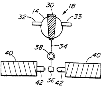
Details of the high speed switch 18 are illustrated in Figure 2 wherein
the opaque leaf 30 moves laterally in the optical path 14 between end stops
32. The optical leaf 30 blanks off a portion of the complete optical path 14
and when moved from a left position to a right position provides a left image
perspective and a right image perspective.
The opaque leaf 30 is supported on the end of an arm 34 which at the
other end has an iron armature 36. A fulcrum or bearing 38 is positioned on
the arm 34.. In the optimized case the relative lengths of the arm portions
is between the opaque leaf 30 and the bearing 38 and between the iron
armature 36 and the bearing 38 are chosen so that it represents the center of
the mass forming the opaque leaf 30, arm 34 and iron armature 36. This
provides a balance for the arm to accelerate, stop and be free of motion in
the
time period between adjacent video or film image frames. In the video
15 embodiment the time periiod between adjacent frames is approximately 0.5
milliseconds and in the emotion picture embodiment this time is the gate
mechanism advancement time, generally slightly more than 0.5 milliseconds.
The bearing 38 is a low friction bearing allowing the arm 34 to move only in
the one plane that is perpendicular to the image path 14. No other motions
2o are allowed as they cause aberrations or distortion in the image.
The iron armature 36 is moved by two electromagnets 40 each having
dampers 42 to assist in stopping the armature 36 and hence the opaque leaf
30 quickly and without any vibration.
The opaque leaf 3(1 is shown as being trapezoidal in shape and in a
preferred embodiment the side face of the trapezoidal shape extends across
the diameter or center line of the image path 14 when in either the left
position or the right position up against end stops 32. The opaque leaf 30
3o moves in a short space oif time and then remains motionless for a
relatively
long period when the image exposure is made in both the left position and the
right position. For a video camera, this exposure time is 16.7 milliseconds or
CA 02123077 2001-O1-25
-12-
33.3 milliseconds at the frame rate. The ratio of 0.5 milliseconds to 16.7
milliseconds defines a 3% duty cycle, or at the frame rate a 1.5% duty cycle.
The switching action has ito occur in this short period and the opaque leaf 30
has to remain stationary without any movement for the exposure time. Motion
of the opaque leaf 30 during the exposure time degrades the image quality.
In the embodimE:nt shown the opaque leaf 30 transverses
perpendicularly across one-half of the image path 14 from end stop 32 to end
stop 33 during the frame advancing time period. Many different types of
io materials may be used for the opaque leaf. The defining parameter is that
the leaf material is opaquE~ in the wave length of interest. For example, in
the
light frequencies the leaf must be opaque to light. The switch functions over
a broad range of spectrum from sonic through infrared light, ultraviolet and
up
to high radio frequencies. In fact any frequency that is capable of having a
i5 camera produce or reproduce an image. The switching device 18 is placed at
a location in the image pai:h 14 typically at or near to the camera lens. In
this
way the opaque leaf 30 defines a constraining plane within the image path.
In the case of a radio frequency, the camera is an antenna, and in the case of
a sonic system, the camera would be a directional microphone, or a horn to
2o receive an ultrasonic beam. In all cases, the opaque leaf 30 divides the
image path into a left perspective and a right perspective such that these two
perspectives can be viewed by the left and right eyes of a viewer to provide a
stereoscopic or three dimensional image.
25 The left image perspective and the right image perspective are seen by
alternating frames of the camera 10 and then as shown in Figure 1, a signal
passes to a video monitor 20 where the left image perspective and the right
image perspective are alternately shown from frame to frame.
3o An electronic synchronization circuit 22, shown in Figure 1, receives a
signal from the camera 10 which represents the time between adjacent
frames or, in the case of a motion picture, the time that the gate mechanism
CA 02123077 2001-O1-25
-13-
advances the film from frame to frame, and a signal from the electronic
synchronization circuit 22 is passed to the electromagnets 40 of the switching
device 18, to produce first the left image perspective and then the right
image
perspective, to ensure that there is synchronization between the camera
frames and the switching device 18. The electromagnet 40 is activated to
move the opaque leaf 3CI during the half millisecond that the video or film
frame changes and then ensure that the opaque leaf 30 remains motionless
during the exposure time of that frame, be it video or film.
lc As shown in Figure 1, the electronic synchronization circuit 22 also
provides a signal to the two lenses in liquid crystal shutter glasses 24
similar
to the type disclosed in U.S. Patent 4,021,846 to Roese. The different lenses
change state from transparent to opaque and it is the electronic
synchronization circuit 22 which ensures that the left image perspective of
the
i= image path is seen by the left eye with the right lens opaque, and the
right
image perspective of the image path seen by the right eye with the left lens
opaque. The lenses switch from being transparent to opaque at the same
speed and in synchronizairion with the movement of the opaque leaf and thus
in synchronization with the frame movement of the camera 10. Thus the
2c alternating image perspectives on the monitor 20 are arranged to be seen by
a viewer's left eye seeing only the left image perspective frames and the
right
eye only the right image perspective frames.
There are many other mechanisms available to differentiate at a
viewers eye between the left image perspective and the right image
perspective, and the present invention is not limited to any one type of
stereoscopic viewing device.
The location of the end stops 32 shown in Figure 2 may be relocated if
3c one requires greater or less movement of the opaque leaf 30 across the
image path 14. Figure 3a illustrates a circular cross-section image path 14 at
that location with a left block 50 and a right block 52 to provide a left
image
CA 02123077 2001-O1-25
-14-
perspective and a right image perspective. The trapezoidal shape of the
opaque leaf 30 divides the image path 14 at a vertical diameter 54, thus the
two blocks 50,52 have the same cross-sectional areas, each a semi circle
with a respective centroid. This creates the joining edge of the left block 50
and the right block 52 during the cycling action.
The amount of stereopsis is varied within the image path 14 by
changing the movement of the opaque leaf 30 between the end stops 32 to
adjust the distance betweE~n the centroids.
i c~
Figure 3b represents less movement of the opaque leaf and the left
block 50 overlaps the right block 52 and has an overlap portion 56 such that
the sizes of the image path portions are greater but the centroids thereof are
closer together. Figure 3c: represents more movement of the opaque leaf and
i_=. the left block 50 and right block 52 do not even join, leaving a gap 58,
whereby the sizes of the image path portions are smaller but the centroids
thereof are further apart. A greater stereopsis is obtained with overlap as
shown in Figure 3b but there is less light for viewing. The best light
situation
occurs with a gap between the blocks 50,52 as shown in Figure 3c, but there
2o is less stereopsis. A preferred embodiment of optical viewing is the
arrangement shown in Figure 3a which best balances light and stereopsis.
In the embodiment described herein, it has been indicated that the left
image perspective is seen by the left eye of a viewer and the right image
perspective is seen by the right eye of the viewer. This arrangement may
depend partly upon the location of the opaque leaf of the switching device in
the optical path. In certalin situations, the perspectives may be physically
or
electronically switched, so the viewer sees with the left eye when the optical
leaf is blocking a right portion of the image path, and vice versa. The
3o arrangement is made to obtain the desired degree of stereopsis and to
obtain
the maximum available light without any refocusing.
CA 02123077 2001-O1-25
-15-
Whereas the opaque leaf 30 has been shown as being trapezoidal, in
other embodiments this shape may be varied. For instance, the opaque leaf
30 may be such that two separate circular image perspectives are formed
spaced apart. Whereas 'the image path 14 is shown as being circular, in
other embodiments this could be rectangular or almost any shape which is
viewed by a camera. In an optical embodiment, the image path 14 or optical
path can be scaled larger or smaller as can the switching device 18.
Maximum energy transmission is provided for stereoscopic imaging through
the single lens system siince only one-half the image path 14 is blocked
io during each cycle as compared to any technique that places energy
absorbing devices in seriea with the active half of a transmission path. The
opaque leaf 30 blocks a portion of the image path 14 leaving the remainder of
the image path open for an image perspective. No additional devices that
absorb energy or distort the properties of the energy source are needed, and
there is no change necessary for focusing the right or left image
perspectives.
The air gaps that are in position between the iron armature 36 and the
electromagnets 40 providle fast release of the armature 36 from residual
magnetic fields stored in the electromagnets 40 for the next cycle. Electronic
2o waveform control of each electromagnet produces magnetic fields which
reduce these residual fields further. The electronic waveform to the
electromagnets 40 of the switch mechanism is formed to create high
acceleration of the leaf, as required during the frame advancing cycle. The
waveform then causes sufficient magnetic force to be produced to hold the
2= armature 36 and hence the opaque leaf 30 in place and stationary during the
exposure period. Just before the end of the exposure period, the waveform
causes a slight reverse polarization of the magnetic field to overcome
residual
permanent magnetic effects in magnets thereof.
3o Other changes may be made to the embodiments shown herein
without departing from the scope of the present invention which is limited
only
by the following claims.