Language selection

Search

Patent 2123168 Summary

Third-party information liability

Some of the information on this Web page has been provided by external sources. The Government of Canada is not responsible for the accuracy, reliability or currency of the information supplied by external sources. Users wishing to rely upon this information should consult directly with the source of the information. Content provided by external sources is not subject to official languages, privacy and accessibility requirements.

Claims and Abstract availability

Any discrepancies in the text and image of the Claims and Abstract are due to differing posting times. Text of the Claims and Abstract are posted:

  • At the time the application is open to public inspection;
  • At the time of issue of the patent (grant).
(12) Patent: (11) CA 2123168
(54) English Title: LAYOUT OF THE INSIDE REAR-VIEW MIRROR DISPLACEMENT MECHANISM
(54) French Title: PLAN DU MECANISME INTERNE DE DEPLACEMENT DE RETROVISEUR
Status: Term Expired - Post Grant Beyond Limit
Bibliographic Data
(51) International Patent Classification (IPC):
  • B60R 01/02 (2006.01)
  • B60R 01/04 (2006.01)
(72) Inventors :
  • DO ESPIRITO SANTO, ANTONIO FERREIRA (Brazil)
(73) Owners :
  • METAGAL INDUSTRIA E COMERCIO LTDA.
(71) Applicants :
  • METAGAL INDUSTRIA E COMERCIO LTDA. (Brazil)
(74) Agent: CASSAN MACLEAN
(74) Associate agent:
(45) Issued: 2004-02-17
(22) Filed Date: 1994-05-09
(41) Open to Public Inspection: 1994-11-08
Examination requested: 1999-02-02
Availability of licence: N/A
Dedicated to the Public: N/A
(25) Language of filing: English

Patent Cooperation Treaty (PCT): No

(30) Application Priority Data:
Application No. Country/Territory Date
7300600 (Brazil) 1993-05-07

Abstracts

English Abstract

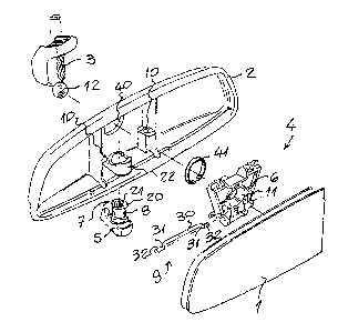
An "INSIDE REAR-VIEW MIRROR DISPLACING MECHANISM LAYOUT" consists of a mirror plate 1 mounted on a frame 2, articulated on the lower end by a supporting arm 3, the upper end of which is assembled on the vehicle's inside ceiling; said frame 2 contains also a displacement mechanism 4 which is driven through lever 5 placed below and includes a trapezoidal plate 6, the smaller base of which is turned downwards and coupled to an inside end 7 of an axis 8 of lever 5; the intermediate region of said plate 6 is mounted on a transversal crankshaft 9, the ends of which bear on supports of frame 2; the central region of said plate 6 has a seat 11 where the sphere 12 is set and which is included on the inferior end of the supporting arm 3 and the upper bigger base of said plate 6 is articulated in frame 2.


French Abstract

« PLAN DU MÉCANISME INTERNE DE DÉPLACEMENT DE RÉTROVISEUR » consistant en une plaque de miroir 1 montée sur un cadre 2, articulée sur l'extrémité inférieure par un bras de soutien 3, l'extrémité supérieure duquel étant assemblée sur le toit interne du véhicule ; ledit cadre 2 contenant également un mécanisme de déplacement 4 qui est entraîné par un levier 5 placé en dessous et incluant une plaque trapézoïdale 6, la base la plus petite duquel étant tournée vers le bas et accouplée à une extrémité intérieure 7 d'un axe 8 de levier 5 ; la région intermédiaire de ladite plaque 6 est montée sur un vilebrequin transversal 9, les extrémités duquel portent sur les soutiens du cadre 2 ; la région centrale de ladite plaque 6 possède un siège 11 où la sphère 12 est installée et qui est inclus sur l'extrémité inférieure du bras de soutien 3 et la base la plus grande supérieure de ladite plaque 6 est articulée dans le cadre 2.

Claims

Note: Claims are shown in the official language in which they were submitted.

I claim:
1. A displacement mechanism of a motor vehicle inside rearview mirror having a
mirror plate
mounted on a frame which is articulated on the lower end of a supporting arm
having an upper end
connected to an inside ceiling of the motor vehicle, the displacement
mechanism comprising a lever
provided with an axle; a transverse crankshaft supportable on the frame; a
sphere provided on a
lower end of the supporting arm; a trapezoidal plate having a smaller base
which is turned downward
and is coupled to an inside end of said axle, an intermediate region mounted
on said transverse
crankshaft, a central region provided far said sphere, and an upper bigger
base articulatable on the
frame, said transverse crankshaft being somewhat resilient and including a
longer intermediate
segment which crosses transversely said trapezoidal plate and is articulated
on it and short biased
segments extending from ends of said intermediate segment and having end
points which are
parallel and not aligned to said intermediate segment and are supportable on
the frame.
2. A displacement mechanism as defined in claim 1; and further comprising
supports provided on
the frame, said transverse crankshaft having ends which bear on said supports,
said short biased
segments having end points which are supported on said supports.

Description

Note: Descriptions are shown in the official language in which they were submitted.


CA 02123168 2003-O1-20
"LAYOUT OF THE INSIDE REAR-VIEW MIRROR DISPLACEMENT
MECHANISM"
FIELD OF THE INVENTION
The present patent has as purpose a displacement mechanism model belongs to
the field
of rear-view mirror components, and which received an original layout, with
the purpose of providing
an improved utilization and increased efficiency with regard to others.
BACKGROUND OF THE INVENTION
Inside rear-view mirrors are already known, which consist of the mirror plate
itself mounted
on a frame, which is articulated with upper end mounted to the area of the
vehicle inside ceiling, and
located at mid level on the upper side of the windshield; said frame has
further a displacement
mechanism which is intended to provide a small movement to the set in order to
avoid the glares
which may dazzle the driver's visibility.
The inside rear-view mirror displacement mechanism layout which is subject of
the present
patent is one contribution more in the sense of providing a more simple and
efficient construction for
this kind of mirror and for that purpose said mechanism includes a trapezoidal
plate, the lower and
smaller base of which is subject to the driving lever, the mid region of said
plate is mounted on a
crankshaft, the ends of which bear on the mirror frame; the central region of
said plate has a seat for
the sphere incorporated to the lower end of the supporting arm and the upper
end of said plate
articulates on the frame.
This form of building the displacement mechanism consubstantiates an extremely
simple and
efficient set, which is capable of properly meeting the expectations of the
motorcar industry and the
consumers of its products.
BRIEF DESCRIPTION OF THE DRAWINGS
The attached drawing shows a model of the inside rear-view mirror displacement
mechanism
layout which is the subject of the patent, in which:
Figure 1 shows the mirror set in an exploded view; and
Figure 2 shows the details of the assembled mirror with partial cut, in which
appears the
displacement mechanism.
DETAILED DESCRIPTION
Pursuant with what is showed in the figures above listed, the inside rear-view
mirror model
which receives the displacement mechanism subject of the present patent
includes the usual mirror
plate 1 mounted on the frame 2 supported in an articulated manner on the lower
end of the support
arm 3, the upper end of which is mounted in the region of the vehicle inside
ceiling. Located besides
and at the mid level of the upper side of the windshield, said frame 2
includes also a displacement

CA 02123168 2003-O1-20
mechanism 4 which is driven through the lever 5 on the lower side of the frame
2 and which is
capable of providing a small movement to the set in order to avoid dazzling
the car's driver.
In the present layout, the displacing mechanism 4 consists of a trapezoidal
plate 6 the lower
base which is turned downwards and is coupled to the inside end 7 of an axis 8
of lever 5; the mid
region of said plate 6 is mounted on a transversal crankshaft 9, the ends of
which bear on supports
of the frame 2; the central region of said plate 6 has a seat 11 for the
sphere 12 which is
incorporated in the lower end of the supporting arm 3, and the upper bigger
base of said plate 6 is
articulated on frame 2.
In detail, the inside end 7 of axis 8 of driving lever 5 has an outside
ferrule 20 provided with
dragging indentations 21, on which is coupled the lower smaller base of plate
6; the mid region of
said axis 8 bears and crosses seat 22 of the lower face of frame 2, and the
outside end of said axis
8 has a lever 5.
The transversal crankshaft 9 is obtained from slightly resilient metal and
consists of a longer
intermediate segment 30 which crosses the transversal conduct of plate 6,
where it is articulated, and
from the ends of said intermediate segment 30 extend shod biased segments 31
which end on the
points 32, which are parallel and not aligned to the intermediate segment 30,
and which are
supported on the supports 10 of frame 2.
The central seat 11 of plate 6 has the shape of a ring, with sphere sector
surface, on which
is inserted and can turn the sphere 12 of the supporting arm 3 and which is in
line to an opening 40
surrounded by a ring 41 provided in the back face of frame 2.
Thus, on a position of the set, the trapezoidal plate 6 and the crankshaft 9
are coplanar and
the intermediate segment 30 of the last is set in a higher position and
compressed, providing a
locking and improved stabilization of the set, even for the vibrations which
are characteristic of the
motorcar vehicle displacement.
On the other hand, when lever 5 is rotated, it pulls the lower smaller base of
plate 6 and the
latter the crankshaft 9, providing an unlocking and abrupt movement of the set
for the other position,
and the stabilization on the latter.

Representative Drawing
A single figure which represents the drawing illustrating the invention.
Administrative Status

2024-08-01:As part of the Next Generation Patents (NGP) transition, the Canadian Patents Database (CPD) now contains a more detailed Event History, which replicates the Event Log of our new back-office solution.

Please note that "Inactive:" events refers to events no longer in use in our new back-office solution.

For a clearer understanding of the status of the application/patent presented on this page, the site Disclaimer , as well as the definitions for Patent , Event History , Maintenance Fee  and Payment History  should be consulted.

Event History

Description Date
Inactive: Expired (new Act pat) 2014-05-09
Inactive: IPC from MCD 2006-03-11
Grant by Issuance 2004-02-17
Inactive: Cover page published 2004-02-16
Inactive: Final fee received 2003-12-03
Pre-grant 2003-12-03
Notice of Allowance is Issued 2003-09-29
Letter Sent 2003-09-29
Inactive: Approved for allowance (AFA) 2003-09-12
Amendment Received - Voluntary Amendment 2003-01-20
Inactive: S.30(2) Rules - Examiner requisition 2002-09-18
Letter Sent 1999-02-15
Inactive: Status info is complete as of Log entry date 1999-02-15
Inactive: Application prosecuted on TS as of Log entry date 1999-02-15
Request for Examination Requirements Determined Compliant 1999-02-02
All Requirements for Examination Determined Compliant 1999-02-02
Application Published (Open to Public Inspection) 1994-11-08

Abandonment History

There is no abandonment history.

Maintenance Fee

The last payment was received on 2003-05-01

Note : If the full payment has not been received on or before the date indicated, a further fee may be required which may be one of the following

  • the reinstatement fee;
  • the late payment fee; or
  • additional fee to reverse deemed expiry.

Patent fees are adjusted on the 1st of January every year. The amounts above are the current amounts if received by December 31 of the current year.
Please refer to the CIPO Patent Fees web page to see all current fee amounts.

Owners on Record

Note: Records showing the ownership history in alphabetical order.

Current Owners on Record
METAGAL INDUSTRIA E COMERCIO LTDA.
Past Owners on Record
ANTONIO FERREIRA DO ESPIRITO SANTO
Past Owners that do not appear in the "Owners on Record" listing will appear in other documentation within the application.
Documents

To view selected files, please enter reCAPTCHA code :


To view images, click a link in the Document Description column. To download the documents, select one or more checkboxes in the first column and then click the "Download Selected in PDF format (Zip Archive)" or the "Download Selected as Single PDF" button.

List of published and non-published patent-specific documents on the CPD .

If you have any difficulty accessing content, you can call the Client Service Centre at 1-866-997-1936 or send them an e-mail at CIPO Client Service Centre.


Document
Description 
Date
(yyyy-mm-dd) 
Number of pages   Size of Image (KB) 
Representative drawing 1998-08-23 1 15
Abstract 2003-01-19 1 18
Description 2003-01-19 2 101
Claims 2003-01-19 1 31
Representative drawing 2003-09-14 1 14
Drawings 1995-06-09 1 32
Abstract 1995-06-09 1 26
Description 1995-06-09 2 113
Claims 1995-06-09 1 58
Acknowledgement of Request for Examination 1999-02-14 1 177
Commissioner's Notice - Application Found Allowable 2003-09-28 1 159
Correspondence 2003-12-02 1 30
Fees 2000-05-07 1 44
Fees 2001-05-02 1 32
Fees 1997-05-06 1 55
Fees 1996-04-28 1 32