Note: Descriptions are shown in the official language in which they were submitted.
;~ WO 93/10331 2 12 3 3 0 6 PC~/~'S92/09921
.
A FRICTION ROCK STABILI~EPc
BACKGROUND OF THE INVENTION
This invention relates generally to friction rock
stabilizers and particularly to friction rock stabilizers
: for forced insertion thereof into an undersized bore in an
earth structure, such as a mine roof or wall.
One type or friction xock stabilizer uses a slit along
its ~length to provide compressibility.
; ~ ~
he use of slitted:friction rock stabilizers to
stabilize: the rock layers in the roofs and walls of mines,
:15 ~tunnels~and other excavations is well known. In
appllcation, these~devices provide the benefit of relatively
e~sy~ nsta11ation and a tight grip, which grows ~tronger
with~time~ and as~rock shifts~. A problem associated with
these~prior art:stabi11zers is that ~heir weight and bulk
contribute to manufacturing and shipping costs, and also can
cause handling problems underground. Also such stabilizers,
~if made from carbon steeI, can be subject to corrosion over
: ~ time.
.
~ 25 The foregoing illustrates limitations known to exist in
'
---''' 2123-306
prior art stabilizers. Thus, it is apparent that it would
be advantageous to provide an alternative direc~d to
overcoming one or more of the limitations set forth above.
~ Accordingly, a suitable alternative is provided including
: ~ features more fully disclosed hereinaf~er.
: .
SUMMARY OF THE I~7ENTION
In one aspect of the lnvention this lS accomplished by
~:~ 10 providing a friction rock stabilizer having an elongated,
:: nondeformable, center spine adapted ~o extend within a
borehole adjacent to the longitudinal center axis of the
~ borehole. Support arms extend transversely outwardly from
:~ :the:spine, for resiliently urging at le~st three
15 ~ ~ spaced-apart frlctlon~s;urfaces into contact with the
borehole~:wall, the:friction surfaces being positioned on an
arc~o~:a clrcle:measured around the center axis of the
borehole/ the arc Sp~nn l ng a center angle of at leRst 18 0
degrees~ The support arms are resiliently compressible
d~ring insertion of the stabilizer into an undersized
~ : ~
~ :~ borehole. ~ ~ ~
.~ : The foregoing and other aspects will become apparent
from ~he following detailed description of the invention
when considered in conjunction with the accompanying drawing
~; 25 figures.
,.
SU55~1TU'rE S~E~
W0~3/1033~ 212 3 3 0 6 Pcr/usg2lo9g21
BRIEF DESCRIPTION OF TEIE DRAWING FIGURES
.
Fig. 1 is a perspective view of the stabilizer of the
invention, with a bottom flange shown in phantom.
: Fig. 2 is a front elevational view of the stabilizer of
the invention.
: Fig. 3 is a side elevational view of the stabilizer of
~ ~; 10 t~e inYention.
: Fig. 4 i~ a top plan view of the stabilizer of the
invention with the borehole wall shown in a dotted line.
15~ Flg.;5 is a top plan view of a preferred embodiment of
the inventlon
: Fig. 6 is a top plan view of an outer li~it e~bodiment
of the invention.
Fig. 7 is a perspective view of an alternate embodiment
of the invention, with a bottom flange shown in phantom.
''
--- 2123306
DETAILED DESCRIPTION
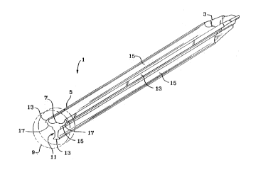
Referring ~o Yig~ 1, there is shown the stabilizer 1,
for use in a conventional borehole (not shown). As is well
known, tbe borehole has a longitudinal center axis, ~-ith the
: borehole wall spaced around ~he axis to form an opening
having a substantially circular cross section, when viewed
~ n a plane transverse to the center axis.
; Stabillzer 1 includes~ a top end 3, a bottom end 5 and
:
0 ~n elongated, nond:eformable, center spine 7 extending
between top end 3~and bottom end 5. Top end 3 is tapered
:to facilitate:insertion of that end into a borehole. Bottom
end~5 has~affixed ther;eto a flange 9 that is larger than the
borehole~diameter.~::Spine 7 is adapted to extend within the
borehQle adjacent::to,~or coinciding with, the longitudinal
a~is~of:the borehole. Extending transversely outwardly from
spine~7~ is support;axm me~n~, shown generally as 11, for
urging at least three~spaced-apart frlction surfaces 13 into
res;ilient contact~with the borehole wall,: when the
stabilizer 1 is forced into an undersized borehole. As seen
in Fig. 4, when friction surfaces 13 contact the borehole
wall 14, they have therebetween a portion of spine 7 spaced
from the borehole wall 14, as is apparent when the invention
is viewed in a plane transvers~ to the longitudinal axis of
the borehole.
5U~3~TlrU i ~ S~
~ W~3/10331 2 1 2 3 3 0 6 PCTJVS92/09g21
Extending between each friction surface 13 and center
spine 7 is a support arm 15. Each support arm~l5 extends
radially and outwardly from spine 7, when viewed in a plane
transverse to the center axis of the borehole. Each support
arm 15 is resiliently compressible in a direction toward
spine 7, during insertion of stabilizer l into an undersized
~ borehole. It should be ùnderstood that arms 15 are adapted
::~: to transmlt the compre~ssive stress in a radial direction
betwee~ surfaces 13 and spine 7, when viewed in a plane
10 ~ transver~e to the center axis of the borehole
:The resilient compression of arms 15 is facilitated by
pro~id~ing an angularly bent elbow portion 17 in arm 15,
between surfa~e 13~and spine 7, at whlch resilient bending
5~ can~occur. I prefer to~for~. the elbow 17 in two of the
three~support arms~15,~wlth one of the~support arms 15 being
strai~ght,~withsut the elbow 17. Alternatively, all or no~e
of~the';arms 15 may~have the elbow 17,~so long as at least
one~support arm I5~is compressible toward spine 7 upon
20: i:nsertion of stabilizer 1 into an undersized borehole.
Support arms 15 are spaced around~spine 7 so that the
friction surfaces 13 contact the borehole wall in at least
three contact areas roughly equally spaced apart from each
other, as measured around a circle drawn with the center
,: -
W~93~331 PCT/US92/099 ~
21'~3306 ~i
axis of the borehole as the center point As used herein~such circle is referred to as a "friction surface circle "
In order that the stabilizer will remain in position after
it has been inserted into the borehole, it should be
understood that the friction surfaces 13 are positioned on
an arc of said friction surface circle, with the arc
sp~nn;ng a center angle of at least 180 degrees It should
be further understood that each friction surface 13 contacts -
the borehole wall over~a length of arc on said-friction
lO~surface~circle, but~contact at a friction surface can also
occyr only at a~ single point, As used herein such length of
àrc~f contact~;on~said friction surface circle is referred
.~ ~
to as~a ''contact~arc length " Any arc distances between any
t~o~friction surfaces~13 herein are measured from the
;15 ~ app~oximate~mldpolnt~ of the respective contact arc lengths
It~can~be~understood that when th- stablliz-r is outside
of~th~e~borehole, 'thè~ diameter of the~friction surface circle
is~greater that~;the~ meter of the~borehole When
stabilizer is within the borehole, the diameter of the
friction surface~circle is~equal to the diameter of the
.: : ~ :
~ ~borehole, as a result of the resilient compression of arms
:
.' 1~.
~ 25 Referring now to Figs 2 and 3, flange portion 9 is
:~
~~ W~93ilO331 PCT/US92/09921
~' 2123306
shown formed at the bottom end of spine 7. Flange 9 can be
a separate piece, fastened by any conventional means, such
as welding~ Alternatively, flange 9 can be manufactured
integrally with the spine 7 and arms 15, as by upset forging
sf the spine 7. I prefer flange 9 to be a solid member, but
flange 9 can also be a hollow, tubular, member. Flange 9
has positioned around it a bearing plate 19. When
stabilizer 1 ic, inserted into the borehole, flange 9 forces
bearing plate 19 into contact with the earth structure being
~~ ~ 10 supported. Plate 19 distributes the axial load of
stabillzer 1 over a larger surfac~ for increased stability,
as:is well known. Flange 9 provides the structure again~t
which conventional insertion devices act to drive stabilizer
l'into the borehole.
:15
Fig:. 5 shows the:preferred embodiment. Three support
arms:~15~are circumferentially spaced:around spine 7 in
apprQ~ tely equal~arc intervals. The center angle 31
etween each contact surface 13 is 120 degrees, as measured
::~
,~ 20 between the approximate midpoints 33 of each con~act arc
length 35. It would be equivalent if the distance between~
~ each contact surface 13 were measured at the extreme edge of
: each contact arc length 35.
,
Fig. 6 shows an alternate embodiment which is an outer
WO93/10331 2 1 2 3 3 0 6 PCT/US92/0992~
limit of the spacing of the contact ~urfaces 13. The
centerangle 37 sp~nn;ng the arc on which all contact
surfaces are positioned is 180 degrees, as measured from the
extreme edge of contact arc lengths 39 and 4l. If center
- 5 angle 37 is less than 180 degrees, the stabilizer would not
be significantly compressed against the borehole wall, and
the stabillzer would tend to fall out of the borehole.
Without being bound to any particular theory of
operation, I believe that thè radial direction of resilient
: compression of arms 15~tends to concentrate the stresses in
:
spine i, and thereby provides for a different stress loading
characteristic, as: compared to prior art slitted
stabilizers. Prior art slitted stabilizers experience a
,~ ~
~bendlng of the structure of the stabilizer generally
parallel ~o ~he borehole wall, similar:to a curved beam, and
do~not:have:any member~adapted to exert a radial force
~: outwardly toward~the borehole wall, directly fxom the
centerline of the borehole. I believe that this feature of
~stress pattern of the invention results in an extremely
~ : strong stabilizer. In addition, because of the presence of
: two distinct elements, the center spine 7 and the arms lS r I:~ can select materials or manufacturing processes that provide
~, a stabilizer with:two distinct and independently variable
strength characteristics: (l) longitudinal tensile strength
-~ WO g3/1~331 2 1 2 3 3 0 6 PC~/USg~/09921
of the spine 7, which affects the breaking strength of the
~tabilizer; and (2) compressive resistance of the arms l~,
which affects the friction holding power of the stabilizer.
Furthermore, I believe the invention permits the use of
:; ; 5 noncorrosive, lightweight materials for the stabilizer, such
as aluminum or high strength plastic. Such materials may
not ordlnarily provide enough bending resistance in a
imple,:curved beam flexure mode, without excessive size or
volume~ However, such materials could provide sufficient
~force~in a:radial compressive mode to be effective as a
abilizer. These~ben~efits can be important in that
:corrosion of the: stabilizer can be avoided and the weight of
st~hi~li7er ~ zed.~In~addition, the~combination of center
spine~7~and radlal arms~15 lends itself to an extrusion
manu~acturing proces~s,~which is a process commonly used with
aluminum~or plastic. ~The extrusion process can provlde
s ~ :~in~cost of;manufacture of the:~stabilizer.
Fig~.~7 shows an~;alternate embo~iment which provides
:20 ~ increased longitudinal tensile strength to stabilizers
xmed from plastic~or~aluminum. Ce~ter:~spine~7 includes
: reinforcing member 51 extending longitudinally along the
:
~length of spine 7,~and embedded in the central portion of
spine 7. Reinforcing member 51 can be friction~lly fit into
~: 25 an aperture formed in central portion of spine 7, or,
~: :
W093~1~331 212 3 3 ~ 6 PCTJUS92/og9~.~
~,,
alternatively, can be fastened therein as by ~usion or
withsuitable adhesives. Reinforcing member 5l can be high
strength carbon steel, when stabilizer 1 is formed from a
noncorrosive material such as aluminum or plastic.
; 5 ~
While I have shown the invention with three support
axms 15, any greater number of such arms:15 can also work.
However, I believe~that fewer than three support arms 15
would tend to result in undesirable anisotropic stiffness
lO~ characterist~ics~in~the stabilizer. Furthermore, I believe
:tha~ fewer than:three:support arms 15 will not provide the
bènefits:of compressive force in a radial direction, along
: with~he overall strength-and stability of the invention as
de~scribed:hereinabove.
~ ~ .
:~ :
,,- ~ : :
,
.
~::