Note: Descriptions are shown in the official language in which they were submitted.
f,....,~ w0 94/06319 PCT/US~I'_'/10446
~~~3~08
MAGNETIC hATCH
HaGkground of the Invention
The invention is directed to a magnetic
latch. More specifically, the invention is directed
to a magnetic latch which is stronger and more
environmentally resistant than conventional magnetic
latches.
Magnetic latches use magnetic force to hold
two objects together. U.S. Patent Nos. 4,021,891
issued to Morita on May 10, 1977, No. 4,453,294
issued to Morita on June 12, 2984, No. 4,455,719
issued to Morita on June 26, 1984, No. 4,700,436
issued to Morita on October 20, 1987, No. 4,458,396
issued to Aoki on July 10, 1984, No. 2,812,203
issued to Scholten on November 5, 1957, No.
3,372,443 issued to Daddona on March 12, 1968, and
No. 3,618,174 issued to Schainholz on November 9,
-1-
...~, .;
,:
,.. ~..:.
S ' .'.\ "
~ \ ,
~~ar~ca~~vt~.~.:~~_:au.....5~.,". ~... , . ,.h" .. .,... _.. ~:',ir~.~.:,~.:
:~. '.:.'~-.;'.. , ~,.w., ~~: w' a,~w.,..~,., .,. . , . . . . ., , i'.v,
WO 94106319 PC'f/US92/1Q'"~
1971 disclose examples of conventional magnetic
latches. U. S. Patent No. 2, 884, 698 issued to Wtlrsch
on May 5, 1959 discloses a magnetic holding device
for holding two pieces of metal together.
The latching strength of these conventional
latches limits their utility. The latching strength
of these latches may be increased by increasing the
size of the latch. However, as the size of the
latch increases, the usefulness of the latch in many
applications decreases due to the bulkiness of the
latch. In addition, larger latches are more
expensive to~inanufacture, thereby reducing the cost
effectiveness of larger latches.
Another disadvantage of these conven~cional
magnetic latches is their unsuitability for use in
a harsh environment. Generally, these conventional
latches contain numerous cracks and crevices which
collect caustic materials which corrode the latch
parts and degrade its effectiveness. In a salt-air
environment, the crevices in these conventional
latches collect salt.and other corrosive materials
which ultimately corrode the latch parts. Thus,
using these conventional latches to hold sails in
place would be ineffective. Similar problems occur
when using magnetic latches in a caustic chemical
environment, for example, when using magnetic
latches to seal protective clothing. Even the
environment of a washing machine will cause most
prior art magnetic latches to rust, limiting their
usefulness on garments.
-2-
~~ 'r WO 94/06319 PCTlUS92/10446
~12330~
Many of. the potential applications for
magnetic latches require that the latch be resistive
to lateral force. Thereforer magnetic attachment
devices which do not resist lateral force, such as
the device disclosed in the X698 patent cited above,
are unsuitable for such applications.
=~u~nary of the Invention
It is an object of the invention, therefore,
to provide a magnetic latch whieh has a strong
latching force as compared with conventional latches
similar in sire.
It is another object of the invention to
provide a magnetic latch which is smaller in overall
size than conventional latches having the same
latching force.
Another object of the invention to provide a
magnetic latch which is thinner than conventional
latches having tha same latching force.
A further object of the invention is to
provide a latch which can withstand water and/or
caustic environments.
Xet another object of the invention is to
provide a magnetic latch which resists lateral
force.
According to a first aspect of the invention,
there is provided a magnetic latch having a ffirst
member and a second member. The first member
includes magnetically attractable material. The
first and/or second members include a mechanism for
-3-
WO 94/06319 PCT/US92/10'~'''~
preventing the lateral movement of the first member
relative to the second member when said first and
second members are latched together. The s a i d
second member includes a first magnet to attract the
first member, wherein the first magnet defines
therein a cavity. The second member also includes
a first solid non-magnetic member arranged inside of
the cavity to enhance attraction between said first
member and said second member. A solid insulating
member can be located on an inner periphery of the
magnet cavity, and further solid non-magnetic
members can be arranged on an outer periphery of the
magnet or elsewhere ~as described below. In a
preferred embodiment the solid insulating member is
in the shape of an open-ended cylinder.
The magnet and the solid insulating member
may be integrally bonded together to resist
corrosion. For certain applications the latch
components are not bonded together.
According to another aspect of the invention,
there is provided a magnetic latch which includes a
first member having a protrusion and a second member
engaging the protrusion to prevent the first member
and the second member from sliding relatively to one
another. The second member includes first and
second magnets to attract the first member. A solid
insulating member is located between the first
magnet and the second magnet to enhance attraction
between the first member and the second member.
The first magnet and the solid insulating
member are integrally bonded together and the second
-4 -
CA 02123308 2002-04-04
magnetic and the solid insulating member are integrally
bonded together. In certain applications the components are
not integrally bonded together.
The provision of two or more concentric magnets,
separated by solid insulating members, allows for reversal
of the polarity of the magnets from magnet to magnet,
further increasing the latching strength.
Therefore, in accordance with the present
invention, there is provided a magnetic latch, comprising:
a first member including magnetically attractable
material; and
a second member including:
a magnet to attract said first member, said magnet
defining a cavity;
a substantially rigid, non-magnetic member
arranged inside of said cavity and positioned proximate to
the inner surface of said magnet, and acting as a means for
enhancing the surface of said magnet, and acting as a means
for enhancing the magnetic attraction between said first and
second members,
said first member being matingly engagable with
said second member, and
said first and second members including means for
preventing the lateral movement of the first member relative
to the second member when said first and second members are
latched together.
Also in accordance with the present invention,
there is provided a magnetic latch comprising:
a) a first member including magnetically
attractable material, said first member comprising flexible4
material;
b) a second member including:
a magnet having a first surface positioned
adjacent said first member when said latch is in a closed
position so as to attract said first member, said magnet
defining a hole therethrough;
1) a backing plate attached to a second surface
of said magnet opposite said first surface;
_5_
CA 02123308 2002-04-04
2) a central projection extending from said
backing plate through at least a portion of the length of
said hole defined within said magnet, said central
projection being separated by a spacing from the inner
surface of the magnet defining said hole; and
3) a solid non-magnetic member positioned within
said spacing; and
c) said first and second members including means
for substantially preventing lateral movement of said first
member relative to said second member when said first and
second members are latched together.
Further in accordance with the present invention,
there is provided a magnetic latch comprising'
a) a first member including magnetically
attractable material, said first member comprising flexible
material;
b) a second member including:
a magnet having a first surface positioned
adjacent said first member when said latch is in a closed
position so as to attract said first member, said magnet
defining a hole therethrough;
1) a backing plate attached to a second surface of
said magnet opposite said first surface;
2) a central projection extending from said
backing plate through the length of said hole defined within
said magnet and having a surface substantially coplanar with
the first surface of said magnet, said central projection
being separated by a spacing from the inner surface of the
magnet defining said hole;
3) a solid non-magnetic member in the form of a
waterproof protective layer substantially filling the entire
spacing between the magnet inner surface and the central
projection;
4) an additional non-magnetic member forming a
waterproof protective layer encapsulating substantially the
entire first surface of said magnet and the coplanar surface
of said projection; and
-5a
CA 02123308 2002-04-04
c) said first and second members including means
for substantially preventing lateral movement of said first
member relative to said second member when said first and
second members are latched together.
Other objects, features and advantages of the
invention will be apparent from the following detailed
description.
Brief Description of the Drawings
The invention will be described in further detail
below with reference to the drawings, wherein:
Figure 1 illustrates a cross section of a first
preferred embodiment of the invention;
Figure 2 illustrates a cross section of the second
member of the Figure 1 preferred embodiment;
Figure 3 illustrates a plan view of the second
member of the Figure 1 preferred embodiment;
Figure 4 illustrates a perspective view of the
second member of the Figure 1 preferred embodiment;
Figures 5A, 5B and 5C illustrate modifications of
the second member of the Figure 1 preferred embodiment;
-5b-
WO 94/06319 PCT/US92/10 ~'
~~~3~~J8
Figures 6A-6G illustrate construction details
of a modification of the Figure 1 preferred
embodiment;
Figures 7A-7I illustrates cross sections of
other modifications of the first preferred
embodiment of the invention;
Figures 8A-8E illustrates cross sections of
yet further modifications of the first preferred
embodiment of the invention;
Figures ~ 9A and 98 show additional
modifications of the first preferred embodiment of
the invention;
Figure 10 illustrates a cross sectional, view
of another modification of the first embodiment of
the invention;
Figure 11 illustrates one technique for
making an alternate form of the Figure 1 preferred
embodiment;
Figure 12A illustrates a perspective view of
the second member of the latch in a second preferred
embodiment of the invention;
Figures 128 and 12C illustrate perspective
views of modifications of the second member of the
Figure 12A preferred embodiment;
Figure 12D is a cross section of the first
member of the latch f or use in the second embodiment
of the invention as illustrated in Figures 12g and
12C;
Figures 12E and 12F illustrated a
modification of the embodiment of Figures 12C and
12D;
-6-
!'~'~'~\ WO 94/06319 2 ~, 2 3 3 0 8 pGTJUS92J10446
Figure 13 illustrates a cross section of a
third preferred embodiment of the invention;
Figure 14 illustrates a cross section of a
fourth preferred embodiment of the invention;
Figure 15 illustrates a cross section of a
fifth preferred embodiment of the invention;
Figure 16 illustrates a cross section of a
sixth preferred embodiment of the invention;
Figure 17 illustrates a cross section of a
seventh preferred embodiment of the invention;
Figure 18 illustrates a cross section of an
eighth preferred embodiment of the invention;
Figure 19 illustrates a cross section of a
ninth preferred embodiment of~the invention; and
Figure 20 illustrates a cross section of a
tenth preferred embodiment of the invention.
Dg,~a>>ed Descristion of the Preferred Embodiments
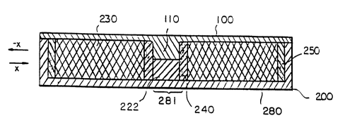
Figure 1 illustrates, in cross section, a
first preferred embodiment of a magnetic latch
according to the invention. As illustrated in
Figure 1, the magnetic latch includes a first, or
male, member 100 and a second, or female, member
200. When the magnetic latch is unlatched, the
first member 100 and the second member 200 are
separated. When the magnetic latch is latched, the
first member 100 and the second m~mber 200 are
connected together as illustrated in Figure 1.
The first member 100 is generally planar in
shape and is magnetically attractable. For example,
..._.,-
...e...e.ne.~.»,.,~,m.,sre._.aaa<..wvxuraa.~..s~sea~.ax~anW::~.,::.y~,...;.1'fh
dS.,~:~.~4\U'~.v~,~,teC.?.\iENl~ilC;~Sl~ ..~:.u.'a2;,".y'~5..~.:~1'u.\~s
~'!i~:~.~:~ .;">.,:. . ~;,v' . ... .
WO 94/06319 PCT/US92/10~
r.
X12330$
it may be formed from a ferromagnetic material such
as iron or an iron-based material. The first member
100 has a protruding segment 110 positioned at the
center of the first member. Although, ~ the
protruding segment 110 is shown integral with the
remaining portions of the first member 100, it may
be separately formed and connected thereto. In most
embodiments, it is important that at least this
protruding segment 110 be magnetically attractable
10' although generally the entire first member will be
magnetically attractable e.g., made of a
ferromagnetic material. Protruding segment 110
engages the second member 200 to prevent the first
member and the second member from moving radially
(sliding) relatively to one another - in the plane
of the view of Figure 1, to prevent movement in the
positive and negative x directions as indicated by
the arrows.
Figures 2, 3, and 4 illustrate the
construction of second member 200, with the first
member 100 removed for clarity. Figure 2 is a cross
sectional view of second member 200. Figure 3 is a
top, or plan, view of second member 200. Figure 4
is a perspective view of second member 200 partially
in section. As seen in Figure 1, and more
particularly in Figures 2-4, the second member
comprises a center section 222, made, for example,
from a ferromagnetic material, a magnet 230 having
an aperture centrally located therein, and a first
segment 240 made of a magnetically insulating .
material. The first segment 240 is a ring like
_g_
v'~ WO 94/06319 PCT/US92/10446
:. .
~12~308
member, positioned within the magnet aperture
against the inner periphery of the magnet 230, and
separates the magnet 230 from the central section
222. There may also optionally be provided a second
section 250 also made of a magnetically insulating
material. The second section 250 is also a ring
like member and surrounds the outer periphery of the
magnet 230. A backing plate 280, made of
ferromagnetic material for example, is provided to
concentrate magnetic flux from the magnet into the
magnet aperture to increase the overall attractive
power of the latch. Additionally, the backing plate
280 may serve to secure the magnet 230 and segments ,
240 and 250. A central portion 281 of the backing
13 plate is aligned with the aperture in the magnet
230. The backing plate may have a rim 280a as
illustrated. The magnet 230, first segment 240,
center section 222 and second segment 250 may be
pressure fit within the housing defined by the
backing plate 280 and rim 280a. When the latch is
in a closed position as illustrated in Figure 1, the
protruding segment 110 and the center section 222
contact or come into proximity with one another, and
the bottom surface of the plate-like member of first
member 100 contacts or comes into proximity with the
surface of magnet 230.
Preferably, grotruding segment 110 is made of
a non-resilient material so that it will not bind to
the first segment 240 upon insertion therein. Most
preferably, the protruding segment is fabricated as
-g-
WO 94/06319 PCT/US92/ll'''""~
a single, unitary member and may be integral with
the first member 100.
It is readily apparent that many variations
of the first embodiment as illustrated in Figures 1
4 may also possible. For example, although these
figures show that the first segment 240 is in the
shape of an open-ended cylinder (top end open) with
a circular cross section, it is apparent that the
aperture defined within the magnet 230 may be of
oval cross section or any other shape with the first
segment 240 being of any shape adapted to fit within
. the aperture, and with the center section 222 being
of any shape adapted to fit within the first segment
240.
Further, while the first segment 240 has been
illustrated as extending through the entire
longitudinal length of the hole defined by the
magnet 230, it may extend only from the bottom
thereof and up to a point where its top surface ;s
co-extensive with the top surface of the center
section 222 as shown in Figure 5A. In such a case,
the first segment 240 may have a tapered top surface
as illustrated in Figure 5A or may be untapered
(flat) .
Further, the magnet aperture need not be
positioned centrally in the magnet, but could be
off-center and still exhibit the enhanced magnetic
attractiveness characteristic of the invention. In
such a case protruding segment 110 would likely be
off-center as well in a manner comparable to the
positioning of the aperture. However, it is not
-10-
.-s .: ~ ~;, . ,ag.. . .,. ::., . . . . .
., .
.,. 3~t:" . ,..~ : . ,., ro ::,~ .t.. . ,_
.,rokh.t:v..:'.... °:4:"R:8'k~'"~''.'~a.'9S.9f~l:;~iah"Z '~'.. ..\
,a"ain . ~.... . .,..~,..a.~. .'~','A1'4. E~.".~.o.t3c. ~Wa~l.. ,
..~~a~k<.1.., ..'~'~n.'~~ .,~a'kia';..,.'~ . .,. . ..
''.. WO 94/06319 PCf/US92/10446
213308
absolutely necessary for closure of the latch that
the protruding segment 110 have a longitudinal
symmetry axis coincident with the symmetry axis of
the aperture, especially where different cross
sectional shapes are used for the protruding segment
and the aperture.
An additional modification may take the form
of a change in the shape of the latch as a whole.
While the first embodiment of Figures 1-4 show a
l0 generally circular shape, the latch can be formed in
any shape necessary to suit a particular
application. For example, the latch can be
rectangularly shaped in which case first segment 240
may be in the shape of an open-ended rectangle. In
general, first segment 240 can be shaped in the
shape of any open-ended polygon.
Another modification involves altogether
deleting center section 222. In this embodiment,
segment 110 of the first member 100 is preferably
long enough to go all the way through the aperture
in magnet 230 so as to be positioned closely
adjacent to or in contact with the canter portion
281 of backing plate 280 when the latch is closed,
thus maximizing the holding power of the latch. In
this case, the first segment 240 extends the full
longitudinal length of the magnet aperture thus
separating and substantially completely filling the
space between the protruding segment 110 and the
inner surface of the magnet aperture. This
modification of the first embodiment is shown in
Figure 5H. However, in soma embodiments, adequate
-11-
"e
.~ v , , . ; a~ .n ~. ~. ; s-.
,, p ,; ~.. ,.. \ ~~ '.,
. , t....~ ,,..~_~,~..4..:...
..,a,~.1 v ~ v~ .1,... ..y, s, ;~ ,~'e
1,.Y.~::ii~.'S.: ': a ..v°. s i..
.,a,:S -.. ~, -, s~~' .:~~: 1 " "~ , ~ ~"~~ ~ ,~. .,1t . .,» :.. ,~'' ~:
f~C~Tø;.y'~~,~°~.1~\"'l~s..,...._.....1~.4_1.'sY~.~.=:r._~,e~'~~.s.degre
e.a~i~>_~~A.',li,.~.,Z,...vs'~s~.~e.~..'Saa~ZESC~~~1W\~~.e~';,..E,t..~......a..
.~..,.u~.....~,~.,y"..w.~~. ..., .. ...,. . . .. . . . .,.
WO 94!06319 PCT/US92110~ ~'"'~
2123308
holding Bower is developed through other points of
contact (e. g. the outer periphery of magnet 230),
and protruding segment 110 need not extend all the
way through aperture 230.
It is also apparent that the length of the
center section 222 may extend through the
longitudinal length of the aperture of the magnet
230 so as to just contact the protruding segment 110
when the latch is closed (latched), as in Figure 1,
or it may alternately be spaced slightly therefrom
but still closely adjacent thereto. The abutment or
close positioning of these two members when the
latch is closed assist in maintaining a strong
closure force. Segments 240 and 250 concentrate
magnetic force produced by magnet 230 into localized
areas in and around the second member 200 to enhance
the attractive force between first member 100 and
second member 200. More specifically, the first
segment 240 focuses magnetic faux toward the center
of the latch, in the aperture in magnet 230, either
through center section 222 or through the center
portion 281 of backing plate 280, or through both.
In this connection it is useful to minimize the
amount of magnetically insulating material in the
flux paths through center section 222 and center
portion 281 to maximize the latching force.
In most embodiments of the invention, the
positioning of the first segment 240 in combination
with the protruding segment 110 and the center
3.0 section 222 is such as to substantially fill the
aperture when the first and second members 100 and
i~~'~ WO 94/06319 PGT/US92/10446
2123308
200 respectively are in the latched position. A
clearance which may be quite small is provided to
permit the protruding segment 110 to slide
longitudinally within the aperture defined by the
interior walls of the first segment 240. In most
embodiments, as for example in Figure 1,
substantially the entire space between the outer
surface of the protruding segment 110 and the inner
surface of the magnet 230 defining the magnet
aperture is occupied by the first segment 240.
Likewise, substantially the entire space between the
outer surface of the center section 222 and the
inner surface of the magnet 230 defining the magnet
aperture is occupied by the first segment 24o which
extends continuously across the entire inner surface
of the magnet defining the magnet aperture. Such a
positioning of the first segment 240 enhances the
attracti~re power of the latch as compared to devices
in which there exists an air space between the
protruding member 110 and the inner surface of the
magnet defining the magnet aperture.
Second segment 250 reduces the fringe field
which would normally exist outside of the outer
perimeter of the magnet and concentrates the
magnetic lines of force so that they have a higher
density in the region at and above the perimeter
itself, namely, in the region indicated by number
277 in Figure 2, and in the rim 280a when such are
provided.
The net effect of these two segments, or
rings, whether a given embodiment contains one, the
-13-
WO 94/06319 PGT/US92/1P~~~~~~~
'~~~~~~g
other or both, is to enhance the latching force for
a given size magnet. Since the latching force is
enhanced over comparably dimensioned latches not
made in accordance with the invention, the overall
size of the inventive latch can be made smaller in
size, either the radial (i. e. , cross sectional area)
extent or thickness or a combination of both. A
smaller size latch constitutes a distinct advantage
over existing latches of larger size in enabling
wider application of the latch such that it may be
employed for use in items of clothing and the like.
Moreover, since magnetic force is concentrated in
the central and peripheral regions .of the magnet
230, the attraction between the first member and the
second member is minimized when the first and second
members are not properly lined up, and is maximized
when they are in alignment.
The embodiment, thus, provides a latch which
has a stronger latching force for a given latch size
or, alternatively, allows the use of a smaller latch
in an application which requires a particular
latching force.
Tn the first preferred embodiment, center
section 222 may be constructed from an iron-based .
material and may be a permanent magnet integral with
or dig ~ inct from magnet 230. The center section 222
can be formed from other ferromagnetic materials as
well. The specific materials used for constructing
the backing glate 280 and rim 280a depend on the
particular application, but in general they will be
made of a ferromagnetic material. In some
-14-
_____~_-~.~__~_..~.....,o.....e..,.Y,.....,r...s"..~-. m,.., .sc~vtswx;iW
tct,~swtt:.a°.;1~1..~.'~llW Is_S!..,.-_TK;,s.~'~~',y~-
Sitw~s,...s~V'.4'~'~~_ ~" ... . _, ~:3-nw : - , ~ . .
''~ °~~ WO 94/06319 PCf/US92/10446
2123308
applications, however, particularly where the rim
280a is utilized, the center section 222 and even
the protruding segment 110 need not be
ferromagnetic. Most preferably, the insulating
effects between the backing plate 280, rim 280a and
the magnet 230 are minimized, for example, by having
them be in close contact, so as not to interfere
with the passage of magnetic flux from the magnet
230 to the backing plate 280. The backing plate 280
l0 and rim 28oa may be constructed from corrosion
resistant material such as stainless steel. Other
materials are also possible for use in the backing
plate. Preferably, these other materials readily
conduct magnetic flux or at least are not flux
insulators.
The segments 240 and 250 are made of any
solid material which does not readily conduct
magnetic flux. Such materials will be termed non-
magnetic materials, or alternatively, magnetically
insulating materials. Segments fabricated from such
non-magnetic materials provide the latch with an
enhancad magnetic attractive force in localized
regions of the latch. Preferably, at least the
segment 240 is made of non-resilient material. The
use of non-resilient material permits fabrication of
the latch with a defined and fixed clearance between
the protrusion 110 and the inner surface of the
segment 240. The clearance is sufficient to permit
facile and non-binding movement of the protrusion
110 within the cavity defined within the segment
240. Most preferably, the segment 240 may be made
-15-
,.,
", ~ ::_:. . ~~'~
.,,r ,
.~ ,
.. ..
l. : iW..: .".
a~-
ta t ' YaWv -v , .~,~ n, ,': a~ . .. R n l a~.'~
T. l 'y . .. V , .',~'. , ~4, . t
v.~ ','t. iii. ~."r., ,~1 r,h
"..e,. -~-.'F':..?L,., 1~IYSw S '~'; .t~ ~. . A, , \.; . ,..~ . . .v, 1'.,
:'za.. -.: '; 1: " y1 . t a 1 - ~, . '~V .
.,~1.. ~ a, ' l." ,.,.2;, ,..r1 1,..'.
S'L'i° ~
.1.. ~."..'~ '.11 " ..\.,. 'i1 \a~;:. '. ~ ~ ,; s1t'. _ v
. S~~' ~'' ~~<. a.. yv\~' ~ ,. 1 ~'~.. "yj~ ~ :w1.. s5. \v.. T a
.r~,. j,.' ~ Ys .'~',. ' ~9 ~ ' 1 ~ ey a~ ~ ~ "., ~ ~~-"~ 1. ,. ,~ ,. ~. .a
.v1. .~-. t ; a \ 1
.."it~~'CY~~~<dr?~~r~~~ a .~-. ~. ~ ;.u 3'f~"iy~.ly ~,;'!,»4y21V..t ,al.-is:~
~ '\t~:
".,
WO 94/06319 PCf/US92/lQw ~
~~.233~8
of a single non-resilient material. The single non-
resilient material may preferably be fabricated as
an integral, unitary structure. By way of example,
and not by way of limitation, the segments 240 and
250 may be formed from a composition containing zinc
or tin, and a carrier such as a ceramic material or
a polymer. The presence of small amounts of
ferromagnetic material or responsiveness, such as
the use of nickel, in the insulating material does
not negatively impact functioning of the latch in an
appreciable way.
Figure 5A illustrates a further modification
of the Figure 1 embodiment and includes a tapered
first segment 240 and a fastener 285 having prongs
286. The prongs are a non-limiting example of a
suitable fastening mechanism to attach the second
member to an element desired to be fastened, such as
an article of clothing, handbag, etc. A similar
fastener, not shown, can be secured to the first
member 100 to secure it to a different portion of
the article desired to be fastened. Figure 5A also
shows a rivet 288 passing through an aperture in
the center section 222 to secure the center section
222, backing plate 280 and fastener 285 together.
Further, a waterproof film, as for example an epoxy,
may be used to completely encapsulate the second
member 200 and its fastener 285 to provide a
corrosive resistent fastening element. The film is
only partially shown in Figure 5A and designated by
the number 290. However, it is understood that the
film envelopes the entire second member 200 and
-16-
<~~~ WO 94/06319 PCT/US92/1044b
2123308
fastener 285 and penetrates the recess defined by
the magnet 230 to provide a water tight, corrosion
resistance structure. A similar film may be used to
cover the first member 100. Further, this
waterproof film may be used to encapsulate the
second and/or first members of all of the
embodiments of the invention. As a non-limiting
example, the waterproof film 290 is also partially
shown in Figure 2.
Figure 5C illustrates yet another
modification 'of the Figure 1 first embodiment in
which the protruding segment 110 has a diameter so
as to just fit within the magnet aperture of magnet .
230 and makes contact, upon closure of the latch,
with the top surfaces of both the center section 222
and the first segment 240. In this case,
substantially all of the space between the
projecting segment 110 and the inner surface of the
magnet 230 defining the magnet aperture is occupied
(upon latch closure) either by the projecting
segment 110 or the combination of the center section
222 and first segment 240. A small clearance
between segment 110 and magnet 230 (not shown) may
also be provided to make possible easier mating of
the first and second members.
Figure 6A illustrates an enlarged view of a
portion of second member 200. In Figure 6A, magnet
' 230 and second segment 250 are secured to backing
glate 280 using an adhesive 292 layer; however, any
other fastening technique can be used to secure the
backing plate 280. For example, instead of an
-17-
WO 94/063t9 PCT/US92/lt~;~""~
2123308
adhesive layer, these elements may be secured by
friction in a close mechanical fit or they may by
held in place by magnetic attraction or a
combination of mechanical fit and magnetic
attraction. Alternately, locking projections or
tabs may be provided on rim 280a or a retaining
cover member can be provided, fitting over the face
of the magnet 230 and engaging lockingly with rim
280a -or the corner between rim 280a and backing
plate 280. One or more rivets as in Figure 5A may
also be utilized. Many other fastening mechanisms
will readily be apparent to one of skill in the art.
Figure 6A also illustrates a variation of the
Figure 1 preferred embodiment. In this variation,
the magnet 230 is covered with a solid, protective
covering member 260 made, for example, of ceramic or
other solid magnetically insulating material. The
covering member 260 extends over most of the surface
area of. magnet 230 but does not extend over the
2o portion defining the. opening of the magnet cavity.
Thus, the covering member 260 does not substantially
interfere with the magnetic attraction through the
central aperture of the magnet 230. A portion of
magnet 230 not covered forms an outer'rim section
270. Pratective covering member 260 not only serves
to protect the magnet from physical mechanical
' damage, but also serves to minimizes the attractive
force between first member 100 and second member 200
when the first and second members are not lined up
properly for latching. It is only by properly
-18-
", WO 94/06319 PGT/US92/10446
212 X308
aligning the first and second members that the high
magnetic attractive forces will be experienced
between the first and second members. In this
manner, the covering member 260 assists in the
attachment process since the protruding segment 110
of the first member 100 can easily slide over the
surface of covering member 260 with minimal
attraction to magnet 230 until the protruding
segment 110 is proximate to the center of the
aperture in magnet 230 and thus near the center
section 222 of the second member 200. Covering
members 26o may be secured by means of adhesive
and/or force fit into place or secured by any other
suitable means.
Alternatively, as shown in Figure 68, the
covering member 260 may extend over the entire
uppermost surface of the magnet 230, and magnetic
engagement is achieved primarily through the
aperture of the magnet 230. As shown in Figure 6C,
the covering member 260 may be formed,integral with
the second segment 250 so as to enhance corrosive
resistant properties of the latch. In yet another
modification, the covering member 260 may extend
over the entire upper face of the second member 200
and serves as the retaining cover member referred to
above. This modification is shown in Figure 6D
wherein the covering member 260 has a lip and is
pressure fit over the rim 280a of the second member
200. Yet a further modification is shown in Figure
6E in which the covering member 260 has a side
extension 260a which extends over the rim 280a and
-19-
WO 94/06319 PCT/US92/10~'"'"
2~233~8
onto the back of the backing plate 28o and is
secured by tabs 260b or similar means adapted to
grip the bottom surface of the backing plate 280.
Figure 6F is similar to Figure 6E but has the
rim 280a omitted. In Figure 6G, the rim 280a is
omitted and the covering member 260, its side
extension 260a and the second segment 250 are all
integrally formed. The side extension and second
segment are indicated by the designation 260a/250.
In Figures 6A-6G, the backing plate 280 is
shown secured to fastener 285 via an adhesive layer
294. The fastener 285 is only partially shown, but
is similar to that illustrated in Figure 5A.
The various cover members shown in Figures
6A-6G, are pre°erably made of magnetically
insulating material; however, materials which are
magnetically attractable to a greater or lesser
degree can also be used. If magnetically
attractable materials are employed in the
construction of the covering member 260, it is
desirable to provide them with a smooth outer
surface to facilitate sliding of projection 110 over
the surface of second member 200 during the process
of aligning the closure.
In all of the modifications shown in Figures
6A-6G, a water proof sealant may be applied as in
the case of Figure 5A.
Still further modifications of the first
embodiment of the invention are shown in Figures 7
and 8. Figure 7A is similar to Figure 1 but omits
the rim 280a of the backing plate 280. Further, an
-20-
"... .~. ,. . .
.,.. ,. ~x
.~ : :~ ~ . -;~ :,, . _. .
~tt'r"W;,...._..,;,...>5'L~?WaL43'3iSFa'~~1:S;.~t~'L'9~~~,~":'k'ra°4L~,0
ea..~~V"".'~'i_. , w, :::;:~'e:..~, ....:,z.:''~\a,:.z.;~:...~"a.,..''~a_.
:;..... .:w2.. . ,.. " ;i~:.: ... ..:.r~a;, ".,..,,
""'i WO 94/06319 PCT/US92/10446
2123308
adhesive layer 292 is shown between the backing
plate 280, magnet 230, first segment 240, second
segment 250 and center section 222. Figure 7H is
similar to that of Figure 7A but includes a ring
member 130 on the first member 100. Figure 7C is
similar to that of Figure 7A omits the second
segment 250. Figure 7D is similar to that of Figure
7C but includes the ring member 130 on the first
member 100. The embodiment of Figure 7E is similar
to that shown in Figure 1 except that the top
portions of the rim 280a and second segment 250
extend upward to be coextensive with the top surface
of first member 100. In this case the diameter of
first member is smaller than in Figure 1 so that the
first member 100 fits within the inner periphery of
~e second segment 250. In Figure 7F, the top
portion of the rim 280a is coextensive with the top
of the first member 100, but the second segment 250
has a top portion which ands below first member 100 .
2o In this case, the diameter of the first member 100
is slightly smaller than the inner diameter of the
rim 280a.
Figure 7G is similar to Figure 1 but shows
the first member having a ring member 130 fitting
over and surrounding the rim 280a. The ring member
130 as well as the protruding segment 110 (Fig.i)
may generically be termed a "protrusion."
Figure 8A shows an alternate modification of
the first embodiment of the invention in which the
first member 100 does not have the protruding
segment 110 and in which the center section 222 as
-21-
,.,"~ .
v."\ y, ~ ';~ ~... , O.'vs
. 4w .e.,~ v \ . ,. , t 7 ,
..y.y. ..y~..,,....;,y~. :. ~ '! ' " ! 'i .
,~ r
!...A. .,~ i . ! : ' :': !! . ,
s, ~, f ~..'~:' S~'~ ~~zka~. .s, 1... :~...~..,.! ...!': ._
.~. fir.. ,. ~. .W_ , v. '. ,. ~a 'Siv >. ~e ,, ~ :: i
at.._...L..!_n._..d~le:lvfi.~.~sss.s.~s~ 1.~~'n.!cl~_..,.,. '~'~'~
...l~lc.'i~:a,n.. ,;..#, ,..,!i. ~, .... .,~ .., . ,..v ,;.,..!". . ~ ,~ :-:
WO 94/06319 PCT/US92lil~'''r'~'.
:>
21~3~08
well as the first segment 240 extend upwardly so as
to be coextensive with the top surface of the magnet
230. Instead of the protruding segment 110, the
first member 100 contains a ring member 130 which is
set into a shoulder formed in the top portion of the
rim 280a. Alternately, as shown in Figure 88, the
ring member 130 can fit over the outer periphery of
the rim 28 0a . Further, the f first member 100 may f it
within the inner periphery of second segment 250, as
shown in Figure 8C, or may fit within the inner
periphery of the rim 280a as shown in Figure 8D. In
Figures 7C, 7F, 7G and 8C-D, the means for
preventing sliding movement of the first and second
members relative to one another is achieved via the
positioning of the first member within the inner
periphery of either the rim 280a or the second
segment 250 of the second member 200.
Figure 8E illustrates yet another
modification of the Figure 1 embodiment in which
both a protruding segment 110 as wall as a ring
member 130 are utilized as a means for securing the
first and second members from relative sliding
(transverse) movement with respect to one another.
Figures 9A and 9B show yet another
modification of the first embodiment of the
invention. In Figure 9A, first member 100 does not
have a protruding member 110 but rather has an
aperture therethrough. The center section 222 of
the second member 200 extends through the aperture
of the first member 100 thereby providing a means
-22-
~'AWS7vi,,A~AiIVk~C~~~.'~7sl~SS'~Su,'ki'a~_~'~"._S~LS1.~!d;.:w~~?tk;t:~t:~.'dJ.
\iV.7.':1V5~:'i~., a~~1\~iY.4 .t!.'W,'.~,.: . ?wvx, :..~~~e.»r;:~s.'~a;ili.;;s
~!5, .'.~.:'r>.: ..,~ , ..
~" ~'j WO 94/06319 PGT/US92/1044b
2123308
for securing the first and second members against
lateral (radial) movement relative to one another.
In Figure 9B, the first segment 240 as well as the
center section 222 extend through the aperture in
the first member 100.
Depending upon the specific application, the
first member can contain only the protruding segment
110 as illustrated in Figure 1, only ring member 130
as illustrated in Figures 8A and 88, or both
protruding segment 110 and ring member 130, as
illustrated in Figure 8E.
In various embodiments of the invention,
center section 222, first segment 240, magnet 230,
and second segment 250 arp integrally bonded
together to eliminate cracks aid crevices in which
caustic materials would otherwise accumulate. This
integrally bonded structure can be achieved by
gluing these members together in a manner such that
the glue fills any void spaces between the various
elements.
Alternatively, Figure l0 illustrates yet
another modification of the first embodiment of the
invention in which in which a first member 301 is
shown disposed above a second mating member 305.
The first member 301 may be composed of a flexible
material, and further may b~e composed of a flexible
material made of a plastic having magnetic particles
embedded therein. Such magnetic material is
commonly used in refrigerator magnets in which the
thin flexible surface is stamped with the suppliers
advertisement. The first member 301 made in this
-23-
WO 94/06319 PCT/US92/t'''°~~6
2123308
fashion permits the magnetic snap to be suitable for
use on clothing where it is desired for the snap to
withstand repeated washing and/or dry cleaning
operations. Flexibility in such situations inhibits
cracking or breaking of the first member. The
second member 305 includes magnet 230 as in the
previous embodiments, but includes backing plate
315a and center section 315b, which may be
integrally formed. The entire second member is now
shown with an outer protective film 319, such as an
epoxy layer which not only serves the function of
the waterproof film 290 of Figures 2 and 5A, but
also includes the first magnetically insulating
materia1~240 of, for example, Figure 1, and/or may
also optionally serve the function of the protective
covering layer 260, depending on its thickness and
composition. The portion of the protective film 319
disposed between the center section 315b and the
magnet 23o is designated by the number 319a.
Further, the top surface o! the center section 315b
may be coated with a thinner layer of the protective
film as shown at 319b. The layers 319, 319a and
319b may be integrally formed with one another and
form a single continuous waterproof protective
layer. This embodiment of the invention is
advantageous for applications where the latch may be
subject to contamination by particulate matter,
since it eliminates crevices where magnetically-
attractable debris might collect.
-24-
...:, _<. " . .,~,.~
,_,..~ "...y , ,~.!.5. ?,'n 1.~\lSlt', y~ '; '~.'::~Wu~, '- ,Y. ,' . ,
y ' , ~t ;,. ~. ~'~. \. '~'~,ri~. v.., '1,'j . . 'l~Sa.~ ., ,~~. ~ . .. . ..
.A..~~t , . .~' SS ~1'~~, . . '~r , , ,
~~°t..~.?21h.~~'.:WyL~._...~~.3.,..,h~,..:~,~_.....
m'.~~.~'1.:,.:~.~.'t'...~~.~~~~~..v<?..~~.,..~a~'~'ni~.,.,.tty... "~ll..e.
..........
;°'''~WO 94/06319 PC'f/US92/10446
~1~3~~8
The latch can be manufactured by a wide
variety of fabrication techniques. A multi-stage
injection molding process,illustrated in Figure 11,
can be used to form an integrally bonded second
member 200. In this figure, a four stage injection
molding process is employed to fabricate the latch.
It is understood that Figure 11 illustrates only one
of many possible techniques to manufacture the
latch.
In Figure 11, step 1, a mold is formed by
slides 962, 964, 966, and 968; bottom portion 940;
and top partions 910, 920, and 930. A space 980 is
defined by these boundaries.
In step 2, magnetic material is injected into
space 980 to form magnet 230. The magnetic material
is subsequently subjected to a magnetic field to
line-up the poles of the magnet in the desired
direction.
In step 3, slides 962, 964, 966, and 968 are
withdrawn as indicated by the arrows in step 3 of
Figure 1l. The voids left after the slides have
been withdrawn are then filled with insulating
material to form segments 240 and 250. Finally, in
step 4 of Figure 11, boundaries 910, 920, 930, and
940 are withdrawn. The process illustrated in
Figure 11 thus ensures that center section 2x2,
solid insulating first segment 240, magnet 230, and
solid insulating second segment 250 are integrally
bonded together without any cracks and crevices. It
is noted that in Figure 11 the magnet 230 and center
section 222 are integrally formed as one piece in
-25-
WO 94/06319 PCT/US92/1!'a~~'~
2123308
the molding process. While such an integral
construction is preferable in the molding operation,
discrete elements may likewise be employed, as in
Figures 1-9. It is understood that in embodiments
of the invention in which the magnet 230 and center
section 222 are integral with one another, the
magnet 230 does not have an aperture therethrough.
In such a case, the magnet may be said to have a ~
cavity therein in which both the center section 222
1o and the first segment 240 are positioned. The term
"cavity" is generic to all embodiments and
modifications of the invention and is intended to
include both a through-hole (aperture, and also a
recess.
Figure 12A illustrates a second member 300 of
a sedond preferred embodiment of the invention. The
second member 300 of Figure 12A is used with the
first member 100 illustrated in Figure 1. The
second member of the second preferred embodiment
2 0 includes a first magnet 3 3 0 ( corresponding to magnet
230 of Figure 2j, a segment 340 of solid insulating
material (corresponding to first segment 240 of
Figure '2), a center section 322 (corresponding to
section 222 of Figure 2) and an outer segment 350 of
solid insulating material (corresponding to second
segment 250 of Figure 2). In addition, the Figure
12A embodiment includes a second magnet 331 which is
separated from magnet 330 by a segment of solid
magnetically insulating material 341. An adhesive
layer 392 shown greatly enlarged may be used to
secure the magnets and segments to a backing plate
-26-
. . .. , . ".. ,. ...".. ~ . ~.
e~umaa~wr~n ..W ~"wxv.evWMYIISICW Y~i.6, i~~..Cls~o......i4'1('a01.41~5NT.f<'t
aa._.W .Slil~Sip:":i~~"k.2121.bT~"'v('l~~~'~tW9A~iy~a>_4W ~.'~v4 W ~-'1.3T....
~a,~'~i~~ a . .u. . ,n t\ .
f ~~ WO 94/06319 PGT/US92/10446
~~.~3308
380 having a rim 380a. Dividing the magnet up into
various sections separated by solid magnetically
insulating material further enhances the latching
force of the magnetic latch by further concentrating
magnetic force in localized areas. When the second
member 20o illustrated in Figure 4 is compared with
a similarly sized second member 300 illustrated in
Figure 12A, the Figure 12A second preferred
embodiment has a greater latching force.
It is understood that section 322 and magnets
330 and 331 may be integral with one another or may
be discretely formed. Further, any two of these
elements may be integrally formed with the third
being discrete.
Figure 12H illustrates a modification of the
Figure 12A preferred embodiment. In Figure 12B, a
g=oove 393 is provided with the magnetically
insulating material 341. The groove serves to
coogerate with a ridge 140 of the first member 100
as illustrated in Figure 12D to assist in the
alignment and securing of the first and second
members. The position of the groove need not be
within the region of the magnetically insulating
material 341.
Figure 12C shows a modification of the
embodiment of Figure 12H wherein the magnetically
insulating material 341 is omitted and the magnet
330 occupies the entire space between the first
segment 240 and the second segment 250. Groove 393
3o is cut into the magnet 330 and cooperates with the
ridge 140 of the first member 100 as shown in Figure
-27-
WO 94/06319 PGT/US92/lr~.'~" ~6
21~33Q8 ,
12D. In a modification to this embodiment as shown
in Figures 12E and 12F, the center section 322 may
be formed to extend to the tog surface of the first
segment 34o so as to be coextensive with the top
surface of the magnet 330. In such a case, the
protruding segment 110 is omitted as in Figure 12F.
Further, the first member may also include a ring
member as in ring member 130 of Figure 78.
Yet a further modification is illustrated in
Figures 7H and 7I which are similar to the
embodiments of Figures 7F and 7G respectively but
wherein the second segment 250 is omitted. In
Figure 7I, the ring member 130 may also be omitted.
Figure 13 illustrates a third preferred
embodiment. The Figare 13 embodiment is similar to
the Figure 12A embodiment with corresponding
elements identified by a number in the 400~s, with
the same tens and units value as in Figure 12A. In
the third preferred embodiment, the polarities of
first magnet 430 and second magnet 431 are reversed
with respect to each other to increase the
attraction force. Also, in the Figure 13
embodiment, center section 422 has the same depth as
the depth of first magnet 430 and second magnet 431,
i.e., it is coextensive therewith. In this -
embodiment, the first member 100 would have the form
of that shown in Figure 8B.
Figure 14 illustrates a fourth preferred
embodiment, with corresponding elements in the
500~x. The Figure 14 embodiment is similar to the
Figure 13 embodiment except that in the Figure 14
_2~_
..\' w , .. ~, . ._ . ; S '...' ,
.. ....yy. .ice ~y ,.,., ....;'iCA,','~l':i '" 'y~ .. '~'t!7.:..',
,- -ss . -. , ~~ ~ ~r,~ .; , ;.<r;~. . ~.
'.~."..v4 ,. , a . , . ~-. . . , .-i''t~: ~. . , ., v. ~'~.a . .. .v ":i.
~i r ,-. a, .., . ~e ..~.Y~
.~1,'~1, ~. t...~~\ l .,S"_. "i ~ .. ~ 6 t. \R.. . iV., s, W -F ~, ,ViV,
:~...'.~'Att~..~~",! :...,L.k~,s'~., a.,._'~~r;'.:'~'e~.,\. ..,"~'t~ _ s~~ .
..., :' ~s, . ,.a , ., a ..\.~.:..~, . ..~ ~.1 , ~. "~~: .. > , .. . . .. _ ..
, . . . . . .
WO 94/06319 PCT/US92/10446
2123308
embodiment center section 522 is recessed. The
first member 100 could now take several forms such
as those shown in Figures 1, 7C, 7D and 7E.
Figure 15 illustrates 'a fifth preferred
embodiment, with corresponding elements in the
600's. The Figure 15 embodiment includes four
magnets 630, 631, 632 and 633. Use of multiple
magnets further increases the available latching
farce. In Figure 15, the polarities of adjacent
magnets are reversed to further increase the
latching force.
Figure 16 illustrates a sixth preferred
embodiment which is similar to the Figure 15 fifth
preferred embodiment, with corresponding elements in
the 700~x, except that the polarities are not
reversed.
Figure 17 illustrates a seventh preferred
embodiment which is similar to the Figure 13 third
preferred embodiment with corresponding elements in
the 800's except that the polarities of the magnets
are not reversed.
Although the invention has been described
with respect to certain preferred embodiments, it is
understood that various modifications and
improvements to the invention may be made by those
skilled in the art without departing from the scope
of the invention, as defined by the appended claims.
For example, the surfaces of the magnets) can be
curved rather than flat as illustrated in Figures
18, 19, and 20. In these figures number in the
900's, 1000, and 1100 series have been used
_2g_
WO 94/06319 PCf/US92/If" ''~
2123308
respectively to identify the corresponding elements
as in previous figures. Moreover, the surfaces of
the magnets in Figures 7-9 and 12-20 may be covered
with a covering member similar to covering member
260 of Figure 6A so as to leave a small perimeter of
the outer magnet uncovered or as in Figures 68-6G so
as to completely cover all the magnet upper
surfaces. For the multi-magnet embodiments of
Figures 12-20, the covering member may cover soma or
1o all or the solid magnetically insulating members.as
well (for example both members 341 and 350 or only
member 341 of Figure 12A) or only the magnet
portions, leaving the solid magnetically insulating
~. members exposed.
It is noted that the magnets utilized in the
embodiments described above may be fabricated using
any conventional technique including the use o!
plastics having magnetic particles embedded therein.
For example, perman~nt magnets made of hard magnetic
powder of ferrite, alnico, rare-earth etc. may be
solidified with a synthetic resin and then
magnetized.
It is further noted that the fasteners and
their associated prongs as shown in Figures 5 and 6
may be used in all of the embodiments and are shown
as non-limiting examples of a mechanism to attach
the magnetic latch to the desired'article, e.g.,
handbag, article of clothing etc. Other potential
fastening means include various types of riveting
means, holes in the closure (housing) or an embedded
or integral loop provided to facilitate attachment ..
-30-
.,.,
r"'vvWO 94/06319 PCT/US92/10446
2123308
by sewing, hook-and-eye means, adhesives of various
types, and various other fastening means know to
those skilled in the art.
In all of the embodiments described above, a
water proof sealing layer (as in Figure 5A) may be
employed to prevent corrosion of the various latch
components.
-31-
,. ., ,~,
-Y,,~,._. ,~.. .~.,,... ..~., ~~~w ~ ~a, r,. ,r:_ ,:Z~rzW '- ,,~_ ~m
v ' ,a, s . ,y ,. ". a , ;!S a.1° ~~ Y~e,- as,. . , ~. : y . ~..x~ .. .
~e. . . r~ a.:
s',-' . ~. -~'u.;&~d~~~~..;Z'.es~,~411~~~?..a~...ch.:~a...,~f..'.'-
.~~:o:.~,t~~lj'4~is ~2.,~_~~ur~s...,:....a~ ~k v..>:... '~. :.. . ~ . .