Note: Descriptions are shown in the official language in which they were submitted.
W ~ ~/l3~l7 PCT/US9Z/09797
2 ~ ?~ 2, ~
D E S C R I P T I O N
Title
REVERSE PHASE AND HIGH DISCHARGE TEMPERATURE
PROTECTION IN A SCROLL COMPRESSOR
Technical Field
This invention relates generally to the protection
of scroll compressors from damage due to the existence of
abnormal operating conditions. More specifically, this
invention relates to protective apparatus within a low side
scroll compressor which selectively permits the internal flow
of refrigerant gas between the compressor's suction and
discharge pressure portions to prevent damage to the scroll
members due to improper electrical hookup and the effects of
abnormally high discharge temperatures.
Background of the Invention
Hermetic compressors, including those of the scroll
type, are of a high or a low side type. A high side compressor
is one in which the motor is disposed in the discharge or high
pressure portion of the compressor shell. A low side
compressor is one in which the motor is disposed in the suction
or low pressure portion of the hermetic shell.
W ~ 93/13317 PCT/US92/09797
212332~
A common problem in hermetic rotary compressors,
including those of the scroll type, is the tendency of
compressed refrigerant gas to flow back from the discharge
pressure portion of the compressor shell, through the
compression mechanism and back to the suction side of the shell
upon compressor shutdown. This backflow is as a result of the
natural tendency of the system within which the compressor is
employed to equalize its internal pressure when the compressor
is de-energized. Such backflow, if not prevented, can cause
the high speed reverse rotation of the compression mechanism
and can lead to potentially serious compressor damage.
The prevention of such backflow upon compressor
shutdown is typically accomplished by the disposition of a
discharge check valve downstream of the aperture through which
gas is discharged from the compressor's compression mechanism.
The discharge check valve is closed by the initial backflow of
refrigerant gas through the compressor which begins immediately
upon compressor shutdown. The closing of the discharge check
valve may be assisted or accelerated by a biasing member such
as a spring.
In scroll compressors having compression mechanisms
which are protected from gas-driven reverse rotation by
apparatus such as a discharge check valve, a problem arises
when the compressor is electrically connected in an improper
manner. Such improper electrical connection can cause the
motor to run in a direction reverse from which it is intended
to run. This problem is recognized in U.S. Patents 4,820,130
and 4,840,545, both of which are assigned to the assignee of
the present invention.
r~ 1/ ~ /U~ /~7
. ~ ~ ~_~ . J~
212332~
Briefly, when a scroll compressor having a
discharge check valve is miswired so that it is caused to run
backwards, the pockets defined between the scroll wraps,
instead of moving radially inward and decreasing in volume,
move radially outward and expand in volume in a pumping action.
In effect, the scroll device functions as a gas expander or
pump as opposed to a compressor.
The expansion of the pockets defined by the scroll
members under such circumstances causes low and even negative
pressures to develop within the pockets because the discharge
check valve, being closed, gives the mechanism no source of gas
to pump from. As a result, the scroll members are drawn
tightly together which can eventually result, to the extent the
compressor motor continues to run backwards, in severe damage
and possibly destruction of the compressor.
Still another difficulty and potential source for
damage in scroll compressors is the development of high
discharge gas temperatures in operation. Such high discharge
temperatures can result from, among other things, the operation
of the compressor in a system where pressure ratios develop
that are outside of the compressor's normal operating range.
Such high discharge gas temperatures can cause thermal growth
within the compressor, and, in particular, thermal growth of
the scroll wraps. The thermal expansion of the scroll wraps
can lead to high wrap tip contact loads and the galling of the
wrap tips
Compressor protection with respect to the
development of high discharge temperatures has historically
involved the disposition of a temperature sensor on a discharge
line leading from the compressor~s hermetic shell or the
W ~ ~ CI~/U~42t~9797
21 23~2~
disposition of an internally mounted temperature sensor closely
proximate to the location at which discharge gas issues from
between the scroll wraps into the discharge portion of the
compressor shell. The former arrangement can be inadequate
because the externally mounted sensor, which is remote from the
critical scroll wrap location, may not sense the existence of
high discharge temperatures sufficiently early to prevent
damage to the scroll members.
The latter arrangement, employing an internally
mounted temperature sensor, while faster acting than
arrangements employing externally mounted sensors, requires the
mounting of the sensor in the discharge pressure portion of the
compressor's hermetic shell. As a result, in low side
compressors the leads of a sensor mounted in the discharge
pressure portion of the shell must be routed out of the
hermetic shell or at least out of the discharge pressure
portion of the shell in order for the signal produced by the
sensor to be used to shut down the compressor's motor.
The need continues to exist to protect hermetic
scroll compressors of the low side type from the damage which
can result from their improper electrical hookup or from the
occurrence of high discharge temperatures, while eliminating
the need to position a temperature sensor in the discharge
portion of the compressor shell and the need to route sensor
leads through or out of the shell's discharge pressure portion.
~ ~I'/US92/09797
2123~2~
Summary of the Invention
With the above background in mind, it is an object
of the present invention to prevent the damage which can result
from the improper electrical hookup of a scroll compressor
motor and the reverse rotation of the driven scroll member
which results therefrom.
It is another object of the present invention to
provide protection for a scroll compressor against the damage
which can result from the development of high compressor
discharge temperatures.
It is a further object of the present invention to
provide protection for a scroll compressor against the damage
which can result from the reverse rotation of the driven scroll
member and from the development of high discharge temperatures
through the action of a combined compressor protection
arrangement.
It is a still further object of the present
invention to provide scroll compressor protection against the
damaging effects of reverse direction scroll rotation and
abnormally high discharge temperatures in a manner which
eliminates the need for disposing a discharge temperature
sensor internal of the discharge pressure portion of the
compressor's shell and the need to route sensor leads out of
the discharge portion of the compressor.
These and other objects of the present invention
will be appreciated when the attached Drawing Figures and the
Description of the Preferred Embodiment found hereinbelow are
considered.
~, 2123329
5a
In accordance with one aspect of the present invention,
there is provided a scroll gas compression apparatus comprising a
shell through which a gas flows when said compression apparatus
is in operation, said shell defining a suction pressure portion
and a discharge pressure portion; a first scroll member disposed
in said shell, said first scroll member having an involute wrap
and defining a discharge aperture, said discharge aperture being
in flow communication with said discharge pressure portion of
said shell; a second scroll member disposed in said shell, said
second scroll member having an involute wrap in interleaving
engagement with the the involute wrap of said first scroll
member, the involute wraps of said first and said second scroll
members cooperating to define a plurality of pockets including a
discharge pocket which is in flow communication with said
discharge aperture of said first scroll member and out of which
compressed gas is discharged when said apparatus is in normal
operation; and means for permitting selective bi-directional gas
flow between said discharge pocket and said suction pressure
portion of said shell, said gas flow occurring in a first
direction when gas pressure in said discharge pocket is less than
gas pressure in said suction pressure portion of said shell and
said flow being in a direction opposite said first direction when
discharge gas temperature exceeds a predetermined temperature.
In accordance with another aspect of the present
invention, there is provided an apparatus for compressing a gas
~ .~,i.
~ ~ Z 3 3 ~ 9
5b
comprising a hermetic shell defining a suction pressure portion
and a discharge pressure portion; means for preventing the
backflow of gas through said discharge pressure portion of said
shell; an orbiting scroll member disposed in said shell, said
orbiting scroll member having an involute wrap; a fixed scroll
member having an involute wrap and defining a discharge aperture,
said discharge aperture being in flow communication with said
discharge pressure portion of said shell, the involute of said
fixed scroll member being in interleaving engagement with the
involute wrap of said orbiting scroll member so as to
cooperatively define a plurality of pockets therebetween
including a discharge pocket, said discharge pocket being in flow
communication with said discharge aperture, said fixed scroll
member further defining a passage, said passage opening into said
suction pressure portion of said shell and into a location within
said apparatus between said discharge pocket and said means for
preventing backflow; and means for controlling gas flow through
said passage in said fixed scroll member, said means for
controlling flow (i.) permitting the flow of gas from said
suction pressure portion of said shell to said discharge pocket
when the pressure in said discharge pocket is less than the
pressure in said suction pressure portion and (ii.) permitting
the flow of gas from said discharge pocket to said suction
pressure portion when the temperature of said gas exceeds a
predetermined temperature.
'Q ~ ~ 2 3 3 7 g
5c
In accordance with a further aspect of the present
invention, there is provided a method for protecting a scroll
compressor against damage upon the occurrence of reverse
direction motor rotation or high discharge temperatures
comprising the steps of: defining a passage in said compressor,
said passage communicating between a suction pressure portion of
said compressor and a portion of said compressor through which
discharge gas flows when said compressor is in normal operation;
and controlling flow through said passage so that (i) gas is
permitted to flow through said passage from said suction pressure
portion to said portion of said compressor through which
discharge gas normally flows when the pressure in said suction
pressure portion exceeds the pressure in said portion of said
compressor through which discharge gas normally flows; (ii) gas
is permitted to flow through said passage from said portion of
said compressor through which discharge gas normally flows to
said suction pressure portion of said compressor when the
temperature of said gas exceeds a predetermined temperature; and
(iii) gas is prevented from flowing through said passage when
said discharge temperature is less than said predetermined
temperature and when the pressure is in said portion of said
compressor through which discharge gas normally flows exceeds the
pressure in said suction pressure portion.
, ~
W O 93/13317 PCT/US92/09797
2123325
The present invention is directed to an arrangement
which selectively permits the flow of refrigerant gas (i.) in a
first direction within a scroll compressor in response to the
development of high compressor discharge temperatures and (ii.)
in the opposite direction within the compressor in response to
the reverse direction rotation of the driven scroll member but
which (iii.) prevents any such flow under normal compressor
operating conditions. Such permitted internal refrigerant flow
during other than normal operating conditions is through an
interruptable passage which within the shell of the compressor
that communicates between the suction pressure portion of the
shell and a portion of the compressor through which discharge
gas flows during normal operation.
The controlled internal refrigerant flow permitted
by the protective arrangement prevents compressor damage which
would otherwise result from the development of high discharge
temperatures or the development of sub-suction pressures
between the scroll members such as can result from reverse
direction compressor motor rotation. When the circumstances of
high discharge temperature or sub-suction pressures between the
scroll members do not exist, refrigerant flow through the
internal passage is prevented.
The invention contemplates the disposition of a
protective valve member in a passage which communicates between
the suction portion of the co~pressor shell and a location
downstream of the aperture through which compressed gas is
discharged from between the scroll members in normal operation.
The valve member is, however, located upstream of the discharge
check valve which operates to cut off the backflow of
compressed gas through the compressor upon normal compressor
shutdown.
w ~ ~ / P ~ /US92/09797
~1 23~.2~
The protective valve member is preferably a free-
floating bimetal valve, unconnected to any other compressor
element, which is disposed in an enlarged portion of the
internal refrigerant passage and which is lifted by the flow of
gas from the suction pressure portion of the compressor through
the passage which occurs when a pressure gradient develops
across the valve. Such a pressure gradient across the valve
will develop under circumstances which include the reverse
direction rotation of the driven scroll member and the
operation of the compressor as an expander as explained above.
Such protective refrigerant flow through the
passage will be from the suction portion of the compressor
she-l, through the passage in which the bimetal valve is
d osed and back to a pocket defined by the scroll members.
This will result in general pressure equalization between the
pockets defined by the scroll members and the suction pressure
portion of the compressor. The compressor, acting as an
expander, will pump from suction back to suction so long as the
improper reverse direction motor rotation continues. In net
effect, the compression apparatus is short-circuited under
such circumstances by the lifting of the protective valve
member in a manner which prevents damage to the scroll members.
Upon the occurrence of abnormally high discharge
temperatures, the bimetal valve, which is normally exposed to
compressor discharge gas through the passage in which it is
disposed, diaphragms in a manner which permits the venting of
discharge gas around it and through the passage back to
suction. By positioning the passage, where it opens into the
suction pressure portion of the compressor, to be near a
thermally actuated motor protection device, the motor
212:~32~ I~,l/U~/U~
protection device can be quickly actuated to shut the
compressor down under high discharge temperature condition.
The compressor is therefore protected from high discharge
temperatures in a manner which does not require the use of a
temperature sensor disposed in the discharge portion of the
shell or the routing of sensor leads out of that portion of the
compressor.
Brief Description of the Drawings
Figure 1 shows a cross-sectional view of a low-side
scroll compressor which embodies the present invention.
Figure 2 is an enlarged partial cross section of
the upper portion of the compressor illustrated in F gure 1
with the compressor in its de-energized state.
Figure 3 is a view taken along line 3-3 of Figure
2.
Figure 4 is a reproduction of Figure 2 showing the
disposition of the compressor discharge valve and gas flow path
through the fixed scroll member when the compressor is in
normal operation.
Figure 5 is a reproduction of Figure 2 illustrating
the operation of the protective arrangement of the present
invention and the gas flow therethrough when the compressor is
miswired so as to run in the reverse direction or when sub-
suction pressures are otherwise caused to develop in the
pockets defined by the scroll members.
~ ~ ~ 23~ ~
Figure 6 is a reproduction of Figure 4 illustrating
the operation of the protective arrangement of the present
5 invention and the gas flow therethrough when abnormally high
discharge temperatures occur while the compressor is in
operation.
Figure 7 is a view taken along the line 7-7 in Figure
2.
Figure 8 is a perspective view of the valve portion of
the protective mechanism.
Figures 9 and 10 are illustrative of an alternative
embodiment of the present invention.
Description of the Preferred Embodiment
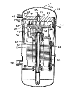
Referring first to Figures 1, 2 and 3, compressor 20
has a hermetic shell 22, in which a fixed scroll member 24 is
20 disposed. Fixed scroll member 24 defines a discharge aperture
26 and has an involute wrap 28 extending from it. An orbiting
scroll member 30 is likewise disposed in shell 22 and likewise
has an extending involute wrap 32 which is disposed in
interleaving engagement with the involute wrap 28 of fixed
25 scroll member 24.
The operating principles of scroll compressors are
well known and described, such as, for instance, in U.S. Patent
4,934,910 which is assigned to the assignee of the present
invention. These general operating principles will therefore
not be discussed in great detail other than as necessary to
describe the present invention.
,.~
WO Y~ l / U~ )9797
~~3325
Scroll members 24 and 30 and their interleaved
involute wraps 28 and 32 cooperate to define a plurality of
pockets therebetween. The volume of the pockets decrease as
they move in a radially inward direction toward discharge
aperture 26 when compressor 20 is in normal operation. The
pockets and their movement are created by the relative orbital
motion of the scroll members. Discharge pocket 34 is the
radially innermost pocket defined by the scroll members and is
in flow communication with discharge aperture 26 of the fixed
scroll member.
Fixed scroll member 24 serves to divide hermetic
shell 22 into a discharge pressure portion 36 and a suction
pressure portion 38. It should be understood that the division
of hermetic shell 22 into a discharge pressure portion 36 and
suction pressure portion 38 can be accomplished by means other
than the use of fixed scroll member 24 such as by the use of an
independent barrier or seal member.
A suction port 40 is provided to permit gas at
suction pressure to enter suction pressure portion 38 of
hermetic shell 22. Suction gas enters the radially outermost
pocket defined by the scroll members, which is cyclically
formed and closed by the orbital movement of the orbiting
scroll member with respect to the fixed scroll member. A
discharge port 42 is provided in shell 22 to permit the
discharge of compressed gas from the discharge portion 36 of
the compressor.
Communicating between discharge aperture 26 and the
discharge portion 36 of shell 22 is a discharge passage 44
through which compressed gas is communicated from discharge
pocket 34, through aperture 26 and to shell discharge portion
w ~ Y~ / PCT/US92/09797
2~ 2332~
36 when the compressor is in normal operation. A passage 46,
in which a valve member 48 is disposed and which is comprised
of passage portions 46a and 46b, communicates between discharge
passage 44 and shell suction pressure portion 38 as will more
thoroughly be described below.
Compressor 20 is driven by an electric motor 50
which is disposed in the suction pressure portion 38 of shell
22 and is therefore a low side compressor. Motor 50 includes a
stator 52 and rotor 54. A drive shaft 56 connects motor rotor
54 and orbiting scroll member 28 through a swing link mechanism
58. Motor 50 includes a thermally actuated line break device
60 associated with stator 52. The line break device is
disposed adjacent the opening of passage 46 into suction
pressure portion 38 of the compressor shell.
Although compressor 20 is illustrated as including
a swing link mechanism, it should be understood that the
present invention is equally applicable to scroll compressors
which do not make use of swing link apparatus including scroll
compressors of the fixed throw type. It must also be
understood that although device 60 is preferably a thermally
actuated line break device which is integral with the
compressor motor, other thermally actuated devices are suitable
for use and are within the scope of the present invention.
Compressor 20 includes means, operable when the
pressure in discharge pressure portion 36 of shell 22 exceeds
the pressure in discharge pocket 34 (such as upon compressor
shutdown), for preventing the backflow of refrigerant gas from
discharge pressure portion of the shell back through passage 44
and into discharge pocket 34 between the scroll members As
illustrated, such means are a discharge check valve assembly
100 which is disposed atop fixed scroll member 24.
W O 93/13317 P ~ /US92/09797
2~ i?3325
Discharge check valve assembly 100 is comprised of
a stop member 120 which is fixedly disposed between guide posts
130 as is best illustrated in Figure 3. Valve assembly 100
includes a free-floating valve element 140 which operates
between a closed position in which it seats over and closes
passage 44 from discharge portion 36 and an open position in
which the flow of discharge gas through passage 44 lifts the
valve element upward so that it seats against stop member 120.
When compressor 20 is shut down and pressures
within shell 22 are equalized, valve element 140 rests over
discharge passage 44, as is illustrated in Figure 2, and is
maintained there by force of gravity. When compressor 22
starts and discharge gas begins to flow through passage 44 from
pocket 34, the flow of the compressed gas lifts valve element
140 and maintains it in the open position resting against stop
member 120 as is illustrated in Figure 4.
Upon compressor shutdown, when orbiting scroll
member 30 ceases to be driven by motor 50 and the scroll
members cease to interact to compress gas between them, gas
will immediately begin to flow back out of the discharge
pressure portion of the shell, into passage 44 and through the
scroll members in an attempt by the system in which the
compressor is employed to equalize its internal pressure. In
doing so, the backflowing gas will immediately carry valve
element 140 downward so as to close off passage 44 from
discharge portion 36 which prevents any further such backflow.
The elevated pressure in discharge portion 36, so long as it
exists, will assist in maintaining valve element 140 seated.
Pressure across the valve element and within the compressor
will eventually equalize as pressures equalize across the
system in which the compressor is employed.
w ~ Y~ 1/ PCT/US92/09797
h ~ ~ 3 3
13
The near immediate closure of the discharge valve
assembly prevents the continued rapid backflow of gas from
discharge portion 36 upon compressor shutdown and, more
importantly, prevents such continued backflow to the scroll
members from the system in which compressor 20 is employed. It
will be appreciated that the system will contain a relatively
much larger volume of discharge pressure gas at such time as
the compressor shuts down than will be found in the discharge
portion of the compressor shell. If orbiting scroll member 28
were permitted to be driven in the reverse direction by such
backflow for too long a period of time, damage to the
compressor would result as has been discussed above.
Because valve element 140 will be in its closed
position whenever the compressor is at rest, including those
instances where the compressor has not yet been initially wired
or has been electrically disconnected, it will be appreciated
that if motor 50 is initially or subsequently miswired such
that orbiting scroll member 28 is driven in a direction
opposite from that which is intended, the pockets defined by
the scroll member, including discharge pocket 34 will be caused
to expand and move radially outward. As a result, compressor
20 will function, in effect, as an expander.
In doing so, the scroll members will act against
the closed discharge check valve assembly lO0 so that pressure
in the compression pockets, including discharge pocket 34, is
pulled down and becomes less than suction pressure. The
pressure may, in fact, approach vacuum because closed valve
element 140 prevents the flow of gas from the discharge
W ~ 2 / U 9 7 9 7
2 1~ 3 3 2 ~
pressure portion of the compressor and eliminates a souce of
gas from which the miswired apparatus can pump. Under such
conditions, the tips of the wraps of the scroll members are
drawn into exceedingly high frictional contact with the
opposing scroll member and severe compressor damage can occur.
As has also been mentioned, the compressor can be
damaged by exceedingly high discharge temperatures which can
occur, for instance, due to operation of the compressor at
pressure ratios outside of its normal operating range. Such
temperatures can cause thermal growth of the scroll members,
particularly in their wraps, with the result that contact loads
on the tips of the scroll members become exceedingly high.
Referring now to Figures 5 and 6, the operation of
the compressor protective apparatus of the present invention
will be discussed in view of the above described abnormal
operating conditions. Referring first to Figure 5, operation
of the protective apparatus of the present invention to prevent
compressor damage due to the development of sub-suction
pressures between the scroll members, such as might occur upon
the reverse rotation of the orbiting scroll member, will be
considered.
As has previously been indicated, in the event that
motor 50 of compressor 20 is miswired so that it runs backward,
compressor 20 will function as an expander. The expansion of
the compression pockets, including discharge pocket 34, causes
a reduction in pressure in those pockets such that pressures
less than suction pressure will occur within the pockets in a
very short time.
w ~ ~ / P~-r/US92/09797
) 3 2 ~.~
Since discharge pocket 34 is open to discharge
passage 44 which, under such circumstances, is closed off from
the discharge pressure portion of the compressor by the seating
of valve element 140 over passage 44, the development of a sub-
suction pressure within discharge pocket 34 will result in the
development of sub-suction pressures both in discharge passage
44 and in the portion 46a of passage 46. Passage portion 46a
is on the discharge pressure side of valve member 48 and opens
into passage 44. Valve member 48 is an otherwise free-floating
element within a closed chamber 62 and is unconnected to any
other compressor element. Chamber 62 in this embodiment is
closed such as by plugs 64a and 64b and can be characterized as
an enlarged portion of passage 62.
The development of a sub-suction pressure in
passage portion 46a will cause a pressure gradient to occur
across valve member 48 since the portion 46b of passage 46,
which is located on the opposite side of valve member 48, is
open to the suction pressure portion of the compressor. It
will be appreciated that when discharge pressure exists in
discharge passage 44, such pressure will be communicated
through passage portion 46a into chamber 62 and will maintain
valve member 48 seated so as to prevent the flow of gas from
passage portion 46a into passage portion 46b. However, if the
compressor is miswired such that the orbiting scroll member is
driven in a reverse direction or if sub-section pressures
should otherwise develop in the compression chambers between
the scroll members, the suction pressure found in passage
portion 46b will exceed the reduced pressure found in passage
portion 46a. This condition causes valve member 48 to be
t'(, l / U~2/~7Y7
2.~ ~3325
16
lifted by the resulting flow of suction pressure gas through
passage 46 from the suction pressure portion of the compressor
into discharge passage 44 and into discharge chamber 34.
Therefore, upon the occurrence of even a slight
pressure differential across free-floating valve member 48, as
would be indicative of the development of sub-suction pressure
in the discharge pocket defined by the scroll wraps, suction
pressure gas will quickly begin to flow through passage 46 and
into discharge pocket 34 to prevent the development of
excessive contact loads on the scroll wrap tips. At such time
as pressure greater than suction pressure comes to exist in
discharge pocket 34 and discharge passage 44, such as by the
proper wiring of the compressor and the resulting compression
of gas between the scroll members, valve member 48 will be
caused to seat within chamber 62 by discharge pressure gas and
will prevent the flow of gas through passage 46 under what
amounts to a normal operating condition.
Referring now to Figures 4 and 6, during normal
compressor operation, as is illustrated in Figure 4, compressed
gas at discharge pressure passes out of discharge chamber 34,
through discharge passage 44 and effects the lifting of valve
element 140 of the discharge check valve assembly 100.
Additionally, that same gas acts on protective valve member 48
to keep it seated within chamber 62 over passage portion 46a
thereby preventing the flow of discharge pressure gas through
passage 46 back to the suction pressure portion of the
compressor shell. Under circumstances where the temperature of
the compressed gas being discharged from discharge chamber 34
becomes abnormally high, however, the exposure of valve member
48 within chamber 62 to such high discharge gas temperatures
will cause valve member 48 to become heated.
~ ~ ~s/~ Y~/~Y7Y7
2 1 ~ 3 ~ 2 ~
Referring concurrently now to Figures 6, 7 and 8,
it will be appreciated that valve member 48 is a bimetal valve
comprised of two layers 48a and 48b of dissimilar metals the
thermal expansion rates of which are dissimilar. The metals
selected for the fabrication of valve member 48 are selected in
accordance with their thermal expansion characteristics so that
when the valve member is heated the differing expansion rates
of the dissimilar metals will cause the valve to diaphragm.
Valve member 48, as is illustrated, has a generally
circular portion the facial area of which is greater than the
cross sectional area of passage portion 46b. The valve member
preferably has three legs such that when it diaphragms due to
being exposed to gas which is at an abnormally high
temperature, the legs of the valve member are maintained in
contact with the interior of chamber 62~ The spaces created
between the legs of the diaphragmed valve member under such
circumstances permit the passage of the abnormally hot
discharge pressure gas between them and into passage portion
46b. The gas then flows into suction pressure portion 38 of
the compressor shell. It will be appreciated that given the
direction of gas flow described under these circumstances the
flow of gas, along with the force of gravity, will maintain the
legs of valve member 48 in contact with an interior surface of
chamber 62 as illustrated.
Passage portion 46b opens into suction pressure
portion 38 of compressor shell 22 at a location proximate to
motor stator 52 and the location on motor stator 52 where
thermally actuated line break device 60 is disposed. Under the
circumstances of the development of abnormally high discharge
W~J ~S/ I s~ I / t'CI'/ U~Y2/09797
2.~2332~
temperatures, the discharge gas will flow through passage 46,
past diaphragmed valve member 48, and will issue into the
suction pressure portion of the compressor. The hot discharge
gas issuing from passage portion 46b will cause thermally
actuated line break device 60 to be heated to a point where
electrical continuity within the motor will be interrupted and
the motor will be de-energized. The thermal characteristics of
valve member 48 and line break 60 are selected to ensure their
operation and the shutdown of the motor before discharge
temperatures reach levels which can potentially cause damage to
the compressor.
It is to be noted that the protective arrangement
of the present invention, as discussed above, eliminates the
need to dispose a discharge temperature sensor in the discharge
pressure portion of the compressor in close proximity to
discharge chamber 34 or to the discharge check valve assembly.
It also eliminates the need to penetrate shell 22 or fixed
scroll member 24 with sensor wiring.
It is also to be noted, as will be discussed
further, that the protective system of the present invention is
equally applicable to compressors which do not have an internal
discharge check valve assembly such as where a discharge check
valve is disposed downstream of the discharge pressure portion
of the compressor shell. If the discharge check valve assembly
is located downstream of the discharge pressure portion of the
compressor shell it will be appreciated that protective passage
46, which in net effect is a passage between a discharge
pressure and a suction pressure portion of the compressor, can
be located anywhere within the compressor so long as it opens
both into the dischar~e and suction pressure portions of the
compressor shell.
~ 1/ PCT/U~92/09797
2~2~2~
19
One such embodiment is illustrated in Figure 9 in
which passage 46' is illustrated as an essentially straight
passage through the fixed scroll member 24' and wherein the
discharge check valve 100' is schematically illustrated as
being disposed in discharge port element 42'. Figure 10
illustrates that protective bimetal valve member 48' is
disposed and confined, in a free-floating manner, in a chamber
62'. Chamber 62', in this embodiment, is open directly to the
discharge pressure portion 36' of the shell and therethrough to
passage 44' and pocket 34~. Valve member 48' is retained in
chamber 62' by a retainer insert 66'. The compressor
protecting apparatus of this embodiment operates on the same
principles as the apparatus disclosed in Figures 1-8 including
the opening of passage 46' into suction pressure portion 38'
adjacent thermally actuated line break device 60'.
As will be appreciated, there are other alternative
arrangements and equivalents which are suggested by and fall
within the scope of the invention described herein. Therefore,
the present invention is not to be limited other than in
accordance with the language of the claims which follow.
What is claimed is: