Note: Descriptions are shown in the official language in which they were submitted.
WO 93/lOS08 PCI/US92/Og9g~
"'`'" 2 ~ ~ 3 ~i 0 9 ~., ,,~,
'
PORT~BhE FI~GERPRI~ SCA~ G APP~RAT~S
FOR IDE~TIFICATION VERIFICATION
5Backqround of the In~ention
F~ld of the I~ention
The present invention relates to apparatus for
the live scanning of fingerprint images and more
particularly to a portable apparatus for the scanning
and capture of fingerprint images and the wire~ess
transmission of said images to a central location for
identity verification.
Da~cription of Background Material
15OYer the years, the most commonly used
techniques for both identity verification an~ the
identification of potential crime suspects have been the
use of fingerprints and photographs or "mug shotsn.
Originally, fingerprinting was done by inking a
20 suspect's finger and applying the inked finger to paper. ~ -
As can be readily understood, fingerprint information in ;
this form was difficult to use. Making a fingerprint
match was an extremely time-consuming task. Digital
technology significantly advanced the art of
fingerprinting. Inked images could be scanned, the
image digitalized and recorded in a manner that could
later be searched in a reasonably expeditious manner by
computer. Problems arose, however, due to the quality
of inked images.~ Over- and under-i~king resulted in
blùrred or vague images; thus rendering the digitalized
information useless. Further, the process of scanning
an inked image was relatively time con~uming. ! '
~ hese and other problems led to nlive
scanning". According to li~e scannlng techniques, the
fingerprint of a ~uspect is scanned directly from the
suspect's finger, as opposed to being scanned from an
inked image of the print. More specifically, live scans
are those procedures which capt~re fingerprint ridge
detail in a manner ~hich allows for the immediate
processing of the fingerprint image with a computer.
WO93/1~08 PCT/US92/~
2123~09
Original work in the field dates back ~o original
patents filed in 1964 concerning techniques u~ed to
capture high contrast images of fingerprint for
photographic or digital capture of fingerprints.
Since their introduction, live scans have
become an important tool for law-enforcement. ~he live
scan has the potential to overcome inherent weaknesses
in ~he ink capture of fingerprints and provide immediate
transmission of fingerpxint images; and allow for image
enhancement if necessary.
These characteristics provide law enforcement
with the ability to improve the quality of the
fingerprint data base, thereby improving the likelihood
that identifications can be made either from latent
fingerprin~s or from identity verification checks. In
addition, live scan fingerprints are easily adaptable to
computerized storage and processing techniques,
increasing cooperation and fingerprint data transfer
between various police agencies.
Systemi6 which optically or optically and
mechanically generate fingerprint images are in uise. ~ ;
Several such fingerprinting systems are disclosed in
Fishbine et al., U.S. Patent Nos. 4,811,414 and -~
4/933 t 976; Ruell German Patent No. 3423886 Al; Becker ~ :
U.S. Patent No. 3,482,498; ~c~ahon U.S. Patent No.
3,975,711; 5chiller U.S. Patent Nos. 4,544,267 and
4,322,163; M~rcus U.S. Patent No. 4,533,837 and White
U.S. Patent No. 3,200,704.
~ While the fingerprinting systems disclosed in~
30 the foregoing patents are capable of providing optical ; ~ -
or optical and mechanical fingerprint i~mage~, said
systems are only suitable or use at a central location
such as the police station. It is evident that there is :
also a need for a portable and lightweight fingerprint ~ -
35 scanning system which can optically generate fingerprint -~
image~ in the field. Such a portable system would be -~
ideal for traffic officers and other law enforcement ~ ~-
. WOg3/1~08 PCT/US92/~ff~
professionals ~ho want to perform an immediate identity
and background check on an individual while in the
field. It is al~o evident that there is a need for a
portable fingerprint system which has the capability for
the wireless transmission of fingerprint images captured
in the field to a central facility for identity
verification using an automated fingerprint
identification system.
It is further evident that there is a need for
a portable fingerprint system which also includes the
capability of capturing a photographic image or "mug
shot" for wireless transmission to a central facility -~
or identity verification using systems such as the FBI
National Crime Information Center Network.
;~
Summary _f the Invention
The present invention is a portable and
lightwei~ht fingerprint ~canning apparatus which can
optically scan and record fingerprint images in the
field and wirelesfily transmit said images to a mobile
unit for proces~ing and subsequent wireless transmi~sion
to a central location for the purpose of providing
immediate identity and background checks on the
individual being fingerprinted. The apparatus of the
present invention includes a finge~print scanner and a
wirel~ss transmitter to transmit the fingerprint image
to a mobile unit. In the preferred embodLment the
present invention also provides for the capability of
using a video camera to capture a photograp~ic image or
"mug ~hotn for wirele~s tran~mission to a mobile unit.
An especially preferred embodiment of the pre~ent
invention also provides the ability to preview the
fingerprint and "mug shot" images on a video monitor and
to control transmission and processing of the
fingerprint and "mug shot" images by the mobile unit
using a terminal or keypad located on the portable
fin~erprint scanning apparatus. The present invention ~ -
WO93/10508 PCT/US92/~
2123~09 ~ ~
allows law enforcement professionals to perform -:
immediate identity and background check~ on an
individual while in the field.
Brief Desc~iption of the Drawin~s
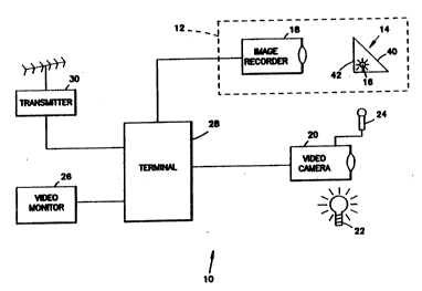
FIG. 1 is a block diagram representation of an
apparatus which can be u~ed to capture fingerprint and
photographic images in the field and transmit said
images via wireless transmission to a central location
for identification verification in accordance with the
present invention.
FI~. 2 i~ a perspective view of the finger
prism shown in FIG. 1.
FIG. 3 is a side view of the f inger pri~m sho~n
15 in FIG. 2. ~:
FIG. 4 is a ~op view of the finger prism shown
in FIG. 2.
. - .-. ~.
: .
Detailed Description of the Preferred Embodiments ~:
In the following Detailed Description of the
Preferred Embodiments, reference is made to the
accompanying Drawings whlch form a part hereof, and in
which~is shown by way of illustration specific .. : -:
embodiments in which the invention may be practiced. It
is:to be understood that the other embodLmant~ may be
utilized and structural change~ may be made without -
departing from the scope of the present invention.
A portable identification verification ~ystem
:10 which can~be used to optically capture produce
30 :~fingerprint:images in accordance with the present
invention~1s:il:lustrated generally in FIG. l. Portable
identific~ation verification system:10 includes 7
fingerprint scanner 12, video camera 20, video monitor
26, and transmitter 30 all interfaced to terminal 28.
35 Terminal 28 includes a keyboard ~not separately shown) -
which is used by an operator to interface with portable
identification verification system 10. Fingerprint
. ~. . -
~ W093/10508 PCT/US92/~8
2123~9
scanner 12 consists of a finger prism 14 and an image
recorder 18. Fingerprint images from the portion of a
finger placed in contact with receiving surface 40 of
finger prism 14 are imaged by image recorder 18. Image
recorder 18 will include a lens and shutter mechanism
(not separately shown). Fingerprint Lmages gen~rated ~y
fingerprint scanner 12 can be displayed on video monitor
26 and transmitted by transmitter 30 to a mobile unit
(not separately shown) for further processing. Video
camera 20 generates a video image, or "mug shot", of the
person being fingerprinted. The video image generated
by video camera 20 can be displayed on the video monitor
26 and transmitted by wireless transmitter 30 to a
mobile unit (not separately shown) for viewing or
recording. Terminal 28 controls whether the image from
fingerprint scanner 12 or video camera 20 is displayed
on video monitor 26. Terminal 28 also controls whether
the image from fingerprint scanner 12 or ~ideo camera 20
is transmitted by wireless transmitter 30 to the mobile
unit. ~erminal 28 al~o transmits control signals via
wireless transmitter 30 to the mobile unit to initiate
processing and digitizing of the images in the mobile
unit.
Optical devices such as finger prism 14 are
well known and disclosed, for example, in NcMahon U.S.
Patent No. 3,975,711; White U.S. Patent No. 3,200,701;
and Fishbin~ et al. ! U.S. Patent Nos. 4,792,226,
4,811,414 and 4,933,976. ~hese devices u~e the optical
principle of total internal reflection. When a finger ! '
is positioned on finger receiving surface 40 (a planer
surface in the preferred embodiment but a curved surface
could be used), an optical image of the ridge and valley
pattern on the surface of the finger (i.e., the
fingerprint) is propagated from image propagation
surface 42. Finger prism 14 is best described with
reference to FIGS. 2 - 4. Finger prism 14 is an optical
device fabricated of a light propaga*ing material, such
WO93/10508 PCT/US92/~
2123~9
as plastic, glass or a combination thereof, which is ~ ~-
characterized by an index of refraction. As shown,
fingex prism 14 has a sloping upper surface or finger
receiving surface 40 and a rear or image propagating -~
5 surface 42. Finger prism 14 also includes a bottom ~ -
surface 44 and two side surfaces 46. Illumination is ~ -
provided on side surfaces 46 by illumination source 16. ~ `
In the preferred embodiment, illumination source 16
consists of light-emitting diodes attached to side `:
surfaces 46 of finger prism 14. Bottom surface 44 is
coated with an opaque material such as black paint. -
Finger prism 14 has overall dimensions such that finqer
rec~iving surface 40 can receive and image at least one
finger 5CI. Image propagating surface 42 is
perpendic:ular to bottom surface 44. In one preferred
embodiment in which finger prism 14 is manufactured of ~-
acrylic material, A1 is 45 and A2 is 20. Finger prism --~
14 is de~igned to utilize the optical principle of
frustration of total internal reflection. These~optical
20 principles are described in Fishbine et al. U.S. Patent ~-
No. 4,811,414 which is hereby incorporated by reference.
These properties result in a Yisual fingerprint image of
a finger placed on image receiving surface 40 being
propagated through image propagation surface 42. The
fingerprint image has "light" areas corresponding to
ridges of the fingerprint and Ndark" areas corresponding
to valley~ of the fingerprint. Other means or optical
devices which provide fingerprint images can also be
used.
Image recorder 18 is mounted with respec~ to
finger prism 14 and configured in such a manner that its
- field of view encompasses the entire image propagation
surface 42. Image recorder 18 continuously Lmages
fingerprint images through its objective lens onto its
image recording media resulting in an image
representative of the light reflected from the parts of
the finger 50 in contact with the image receiving ~-
- WO93/10508 2 ~ PCT/U~92/~
surface 40. The recorded image looks like the -
photographic negative of the fingerprint image. In the
preferred embodiment, image recorder 18 is a video
camera that continually images fingerprin~ images
through its objective lens, and genera~es frames of
video signals representative thereof. Any commercially
available video cameras can be used. In the preferred
embodiment image recorder 18 i5 a Model XC-77 video
camera manufactured by Sony Corporation. Alternatively,
any type of electronic camera or imager such as an
electronically shuttered CCD array or
electrophotographic recording device can be used.
The video signal output of image rec~rder 18
can be viewed on video monitor 26. In the preferred
embodiment, video monitor 26 is a Casio 3 inch LCD
monitor. The video signal output of image recorder 18
is also wirelessly transmitted by transmitter 30 to a
mobile unit (not separately shown). When the operator
desires to "capture" a fingerprin~ image being previewed
on video monitor 26, the operator will actuate a key on
terminal 28 which generates a signal transmitted by
transmitter 30 to the mobile unit that capture and
processing of the fingerprint image should be initiated.
In the preferred embodiment, terminal 28 has a dual-tone
multifrequency tDTNF) keypad. Upon receiving the signal
~from terminal 28 the mobile unit digitizes and-processes
the fingerprint image in accordance with methods
described in U.S. Patent Nos. 4,811,414 and 4,933,976.
After image processing and compression in the mobile
unit, the image can be transmitted wirelessly to a base
unit at a central facility, such as a police station,
for identity verification using an automated fingerprint
identification system such as the FBI's National Crime
Information Center Network.
Video camera 20 is a standard video camera that
continuously receives images through its objective lens,
and generates frames of video signals representative
WO93/1~08 PCT/US92/~B ~ -
~ '`': ~
2 1 2 3 ~ 0 9 8
thereof. Commercially available video cameras using -~
conventional rasters and scanning rates can be used. In
the preferred embodiment of system 10, video camera 20 .
is a standard 8 mm video camera Model XC-77 manufactured
5 by Sony Corporation. Any comm~ercially available video `-
camera capable of obtaining a full face or "mug shot"
image would be suitable. The video signals genera~ed by
~ideo camera 20 may be previewed on video monitor 26 and ~ `
wirelessly tran~mitted by transmitter 30 to the mobile
unit (not separately shown). When the operator viewing
the image in video monitor 26 desire~ to capture a "mug
shot" image, the operator will actuate a key on terminal
18 which sends a signal via transmitter 30 to the mobile
unit inst:ructing the mobile unit to capture the image
1~ utilizing standard digitizer or frame grabber
technology. Video camlera 20 may also be connected to
misrophonle 24 and be provided with an illumination -
source 22. Video camera 20 may al~o optionally be used -~
to videotape a person suspected of driving while under
20 the influence of alcohol or drugs. In this situation ~-;
the video signal transmitted by transmitter 30 to the
mobile unit can be recorded on a video tape recorder ;
attached to the mobile unit.
In the preferred embodiment wireless
transmitter 30 and the corresponding receiver in the
mobile unit use radio frequency transmission. But any
other wireless transmission means such as microwave or -~
infrared transmission could be utilized.
- Although the present in~ention has,been ! ;
described with reference to the preferred embodiments,
those~skilled in the art will recognize that changes may
be made in the form and detail without departing from `~
the spirit and scope of the inventLon.