Note: Descriptions are shown in the official language in which they were submitted.
- 1- CA2123539
- 27879-140
TITLE OF THE INVENTION
CONTROL KEY DEVICE
BACKGROUND OF THE INVENTION
The present invention generally relates to control key
devices, and more particularly to a control key device which may
be used as an input device for specifying a moving direction of
a displayed character or the like on a video game apparatus or
a portable electronic game apparatus.
A control key device having an improved response
characteristic was previously proposed in a Japanese Laid-Open
Patent Application No. 6-52757. This previously proposed
control key device includes a resilient member which has four
bulges with electrically conductive portions, a contact pressing
member having a spherical surface and four legs resting on the
four bulges of the resilient member, a dome-shaped portion of a
casing having a bottom surface making contact with the spherical
surface of the contact pressing member, and a key fixed to the
contact pressing member via an opening in the curved portion.
A bottom surface of this key makes contact with a top surface
of the dome-shaped portion.
When the key is tilted in one direction from a home
position, the bottom surface of the key slides on the top
surface of the dome-shaped portion, and the spherical surface
of the contact pressing member slides with respect to the bottom
surface of the curved portion. As a result, one of the legs
pushes a corresponding bulge of the resilient member, and the
electrically conductive portion of this bulge makes electrical
~ - 2 - CA2123539
- 27879-140
contact with electrodes on the circuit board.
Because the movement of the key is guided by both the
curved upper and inner surfaces of the dome-shaped portion
while the bottom surface of the key contacts the upper surface
of the dome-shaped portion and the top surface of the contact
pressing member contacts the inner surface of the dome-shaped
portion, the vertical movement of the key is restricted, and
accordingly, a large tilting movement and a relatlvely strong
stroke are required to tilt the key so as to make the
electrically conductive portion contact the electrodes on the
circuit board. Furthermore, because the spherical surface of
the contact pressing member slides against the bottom surface
of the curved portion of the casing, the spherical surface of
the contact pressing member may stick to the bottom surface of
the curved portion depending on the friction between the two
surfaces. This sticking phenomenon may occur particularly when
the spherical surface of the contact pressing member hits
against an edge of the bottom surface of the curved portion and
gets caught by the edge. When such a sticking occurs, the key
will be locked to the tilted position, and the operator would
have to forcibly return the key to the home position because the
key will not return to the home position by itself.
SUMMARY OF THE INVENTION
Accordingly, it is a general object of the present
invention to provide a novel and useful control key device in
which the problems described above are eliminated.
Another object of the present invention is to provide
_~ '
_ 3 _ CA2123539
27879-140
a control key device having an improved response characteristic
with a light and smooth touch key operation as well as a quick
operation of the key.
Still another object of the present invention is to
provide a control key device in which the key can be tilted
with relatively small force and stroke.
Still another object of the present invention is to
provide a control key device which can positively prevent
sticking of a key at a tilted position so that the tilted key
will always return to a home position by itself.
A further object of the present invention is to
provide a control key device in which the gap or space between
the key top and the wall of the casing surrounding the key is
minimized to reduce the space required to provide the key.
Other objects and further features of the present
invention will be apparent from the following detailed
description when read in conjunction with the accompanying
drawings.
In accordance with the present invention, there is
provided a control key device comprising a substrate having a
plurality of electrical contact portions, a plurality of
resilient portions disposed on said substrate and each having a
conductive portion disposed on and closely spaced from the
corresponding electrical contact portion so that each of said
conductive portions constitutes an electrical switch with the
corresponding electrical contact portion, a control key disposed
on said plurality of resilient portions so that when said
~s '~A
CA21 23539
control key tilts one of said switches is closed, guiding
means disposed beneath said control key, said guiding means
and said control key having mating surfaces corresponding to
each other, and supporting means for supporting said guiding
means so as to be spaced from said substrate, characterized in
that: said control key in its home position is disposed at a
position closely spaced from said guiding means, and that said
control key moves into contact with said guiding means at said
mating surfaces when a manipulating force is applied to said
control key.
In accordance with another aspect of the invention,
there is provided a control key device comprising: a
substrate with a plurality of contact portions disposed in a
symmetrical positional relationship; a plurality of resilient
portions disposed on said substrate and each having a
conductive portion disposed on and closely spaced from the
corresponding electrical contact portion so that each of said
conductive portions constitutes an electrical switch with the
corresponding electrical contact portion; a dome-shaped
portion having a through hole, an upper surface and stopper
means; supporting means for supporting said dome-shaped
portion so as to be spaced from said substrate; a control key
having a key-top member with a bottom surface facing said
upper surface of said dome-shaped portion and a contact
pressing member secured to said key-top member via said
through hole, said contact pressing member having an upper
portion facing said stopper means and lower portions disposed
~B 27879-140
CA2 ~ 23539
s
on said plurality of resilient portions so that one of said
electrical switches is closed when said control key tilts,
said control key being maintained in its home position by said
stopper means and said plurality of resilient portions when
said key-top member is free of a manipulating force;
characterized in that said control key device further
comprises a sticking prevention means for preventing said
control key from sticking at a tilting position when said key-
top member is released from the tilting position.
In according with a further aspect of the invention,
there is provided a control key device comprising a substrate
having a plurality of electrical contact portions, a plurality
of resilient portions disposed on said substrate and each
having a conductive portion disposed on and closely spaced
from the corresponding electrical contact portion so that each
of said conductive portions constitutes an electrical switch
with the corresponding electrical contact portion, a control
key disposed on said plurality of resilient portions so that
when said control key tilts one of said electrical switches is
closed, guiding means disposed beneath said control key, said
guiding means and said control key having mating surface-s
corresponding to each other, characterized in that said
control key device further comprises first supporting means
for supporting said guiding means so as to be spaced from said
substrate and to isolate a center portion of said substrate
27879-140
CA21 235-39
5a
from a force applied to said control key, and a second
supporting means supporting said substrate at the portions at
which said electrical contact portions are formed.
27879-140
' - 6 - CA2123539
27879-140
BRIEF DESCRIPTION OF THE DRAWINGS
Figure 1 is a perspective view showing an embodiment
of the external appearance of a control key device according to
the present invention;
Figure 2 is a cross sectional view showing a first
embodiment of the control key device according to the present
invention;
Figure 3 is a cross sectional view showing the first
embodiment in a disassembled state;
Figure 4 is a cross sectional view showing the first
embodiment in a state where a key is tilted from a home
position;
Figure 5 is a cross sectional view for explaining
sticking of the key at the tilted position;
Figure 6 is a cross sectional view showing an
important part of a second embodiment of the control key device
according to the present invention;
Figure 7 is a cross sectional view showing an
important part of a third embodiment of the control key device
according to the present invention;
Figure 8 is a cross sectional view showing a fourth
embodiment of the control key device according to the present
invention;
Figure 9 is a cross sectional view showing a fifth
embodiment of the control key device according to the present
invention;
Figure 10 is a perspective view showing the fifth
embodiment in a disassembled state;
.i;,l~~
~ '
CA2 1 23539
-- 7 --
27879-140
Figure 11 is a plan view showing the fifth embodiment;
Figure 12 is a cross sectional view showing a sixth
embodiment of the control key device according to the present
invention;
Figure 13 is a perspective view showing the sixth
embodiment in a disassembled state; and
Figures 14A and 14B respectively are cross sectional
views for explaining the switch action of the control key
device.
DESCRIPTION OF THE PREFERRED EMBODIMENTS
Figure 1 is a perspective view showing an embodiment
of the external appearance of a control key device according to
the present invention. As shown in Figure 1, a control key
device 1 generally includes a key 2, a casing 100 and a
plurality of buttons 110. The casing 100 is made up of upper
and lower halves 3 and 7. The key 2 has projections 2a
through 2d which an operator pushes with his finger to tilt the
key 2. I~hen one of the projections 2a through 3d is pushed,
the key 2 is tilted to specify a moving direction of a displayed
character or the like on a video game apparatus or a portable
electronic game apparatus. The buttons 110 are manipulated to
control various functions modes of the video or electronic game.
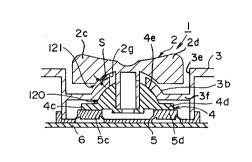
Figure 2 is a cross sectional view showing a first
embodiment of the control key device according to the present
invention, and Figure 3 is a cross sectional view showing the
first embodiment in a disassembled state. The cross section in
Figure 2 is viewed at the II-II line in Figure 1.
. ~
- 8 - C A 2 1 23539
- 27879-140
As shown in Figures 2 and 3, the key portion of the
control key device 1 generally includes the key 2, a dome-
shaped portion 3b of the upper half 3, a contact pressing member
4, and a resilient member 5, and a wiring board (or substrate)
6. A stem portion 2e of the key 2 is secured on the contact
pressing member 4 via a hole 3a in the dome-shaped portion 3b
of the upper half 3.
The upper half 3 has a cavity 3e and the dome-shaped
portion is supported by a flat bottom portion 3f which extends
from the side wall in the cavity 3e of the upper half 3. The
flat bottom portion 3f suspends the dome-shaped portion spaced
from the substrate 6 and an extra force applied to the top of
the key 2 by an operator is prevented from reaching the
substrate 6.
In a home position of the key 2 shown in Figure 2, a
bottom surface 2g of the key 2 makes contact with a top surface
of the dome-shaped portion 3b. In addition, a bottom surface
of the dome-shaped portion 3b makes contact with a spherical
surface portion 4e of the contact pressing member 4.
Furthermore, in the home position of the key 2, legs
4a through 4d (only 4c and 4d shown in Figures 2 and 3) of the
contact pressing member 4 rests on corresponding bulges 5a
through 5d (only 5c and 5d shown in Figures 2 and 3) of the
resilient member 5 so that there exists a gap 5 between the
spherical bottom surface 2g and the top surface of the dome-
shaped portion 3b. An electrically conductive portion is
provided at least on a bottom of each of the bulge 5a through
..
~" , .
.-- --
CA21 23539
g
_ 27879-140
5d. For example, as shown in Figure 14AI the bulge 5c consists
of a top portion 5cl of a disk shape, a conductive portion 5c3
provided on the bottom of the top portion 5cl and a skirt
portion 5c2 of a trapezoidal cylinder shape which movably
supports the top portion 5cl. On the substrate 6 there are
provided a pair of contacts or electrodes 6cl and 6c2. The
conductive portion 5c3 constitutes a movable switch with the
electrodes 6cl and 6c2. Each of the bulges 5a through 5d has
the same or similar structure and constitutes a switch with the
electrode under the conductive portion. The arrangement of the
electrodes 6al, 6a2 through 6dl, 6d2 is depicted in Figures 10
and 13. The electrically conductive portion does not make
electrical contact with a corresponding electrical contact of
the wiring board 6 in the home position of the key 2 shown in
Figure 2.
When the operator pushes down, for example, the key
2 at the projection 2c, the key 2 tilts from the home position
and the leg 4c of the contact pressing member 4 presses the
corresponding bulge 5c in Figure 4. For example, as shown in
Figure 14B, the electrically conductive portion 5c3 makes
electrical contact with the corresponding electrodes 6cl and
6c2 of the wiring board 6. As a result, an electrical circuit
6c shown in Figure 10 or 13 detects the tilted direction of the
key 2 based on the contact at the electrodes 6cl and 6c2.
When the operator lets go of the tilted key 2 in
Figure 4, the key 2 returns to the home position shown in
Figure 2 by itself due to the resilient force of the resilient
CA21 ~3~39
-- 10 --
27879-140
member 5I particularly of the skirt portion 5c2 at the bulge
5c.
When the key 2 is pushed at its top surface, the key
2 moves down to decrease the gap s so that the bottom surface
2g of the key 2 contacts the top surface of the dome-shaped
portion 3b/ and the key 2 tilts from the home position shown
in Figure 2 to the tilted position shown in Figure 4, while the
bottom surface 2g of the key 2 slides on the top surface of the
dome-shaped portion 3b, and the spherical surface portion 4e of
the contact pressing member 4 comes off the bottom surface of
the dome-shaped portion 3b. The bottom surface 2g and the top
surface of the dome-shaped portion 3b each have mutually mating
spherical surfaces, and accordingly, the key 2 moves smoothly
on the dome-shaped portion 3b when the key 2 receives a press-
ing force at the top surface. On the other hand, the contact
pressing member tilts while its top surface is spaced apart
from the bottom surface of the dome-shaped portion 3b, which
reduces the friction between the contact pressing member 4 and
the dome-shaped portion 3b.
The movement of the key 2 of going down by the force
applied at the top surface of the key 2 leads the bulges 5a
through 5d to move down closer to the electrodes on the circuit
board 6 by the gap s between the key 2 and the dome-shaped
portion 3b and the key 2 tilts along the top surface of the
dome-shaped portion 3b. These movements require less tilting
movement to make the conductive portion 5c3 in contact with the
electrode than in the configuration as proposed in the Japanese
~ ,~
A2 1 23539
27879-140
Laid-Open Patent Application No. 6-52757 in which there is not
provided a gap between the bottom surface of the key and the
top surface of the dome-shaped portion.
Then, when the operator releases the pushing force
the bottom surface 2g of the key 2 comes off the top surface of
the dome-shaped portion 3b and the spherical surface portion 4e
of the contact pressing member 4 contacts and slides against
the inner spherical surface of the dome-shaped portion 3b when
the key 2 returns from the tilted position to the home position.
Thus, the light and smooth touch in the manipulation of the key
2 is obtained.
However, the friction between the spherical surface
portion 4e and the bottom surface of the dome-shaped portion
3b, there is a possibility of the key 2 sticking at the tilted
position or an intermediate position between the tilted
position and the home position.
For this reason, it is conceivable to increase the
resilient force exerted by the resilient member 5. However,
this would require more force to tilt the key 2 from the home
position to the tilted position, and the light and smooth touch
(so-called feather touch) key operation becomes hindered to
make and a quick operation of the key 2 becomes difficult.
On the other hand, in order to increase the resilient
force of the resilient member 5, it is conceivable to increase
the gap between the electrically conductive portions of the
bulges 5a through 5d and the wiring board 6 in the home
position of the key 2. But in this latter case, it would
~ .~
~.
- 12 - C~ 2 1 23539
_ 27879-140
require the key 2 to be tilted with a larger stroke in order
to achieve the electrical contact between the electrically
conductive portion and the corresponding electrodes of the
wiring board 6. As a result, the light and smooth touch key
operation becomes hindered to make, and it becomes impossible
to make a quick key operation. Furthermore, the need to tilt
the key 2 with the large stroke would require more space to
provide the key 2 on the control key device 1.
In addition, the above described sticking of the key
2 may occur particularly when the spherical surface portion 4e
of the contact pressing member 4 pushes against an edge 3E at
the bottom part of the dome-shaped portion 3b as shown in
Figure 5. In order to guarantee the restoration of the pressed
bulges 5a through 5d, it is in general necessary to provide a
gap of approximately 1 mm between the electrically conductive
portion of the bulge and the wiring board 6 in the home
position of the key 2. For this reason, there is a limit to
reducing the pushing force of the spherical surface portion 4e
acting on the edge 3E. In other words, the restoration of the
bulges 5a through 5d and thus the automatic return of the
tilted key 2 to the home position may not be guaranteed if the
resilient force exerted by the resilient member 5 is too weak,
but if the resilient force exerted by the resilient member 5 is
too strong, the possibility of the spherical surface portion 4e
becoming caught by the edge 3E increases.
In first embodiment of the control key device of the
present invention, a lubricant film 120 is provided at least
,7.i~ ~ .
(~a2l 23539
~ - 13 -
- 27879-140
between the spherical surface portion 4e and the bottom surface
of the dome-shaped portion 3b. For example, a grease or the
like may be used as the lubricant. In addition, it is also
possible to provide a lubricant film 121 between the bottom
surface 2g of the key 2 and the top surface of the dome-shaped
portion 3b. The lubricant films 120 and 121 may be coated on
either of the two surfaces which relatively slide with respect
to one another, for example.
According to the first embodiment with the lubricant,
it is possible to prevent sticking of the key 2 at the tilted
position or the intermediate position between the tilted
position and the home position. In addition, it is possible
to maintain the light and smooth touch key operation and to
make the quick operation of the key 2.
As a modification of the first embodiment with the
lubricant, it is possible to use a material which has a
lubricative surface for the key 2, the dome-shaped portion 3b,
and the spherical portion 4e. According to this modification,
it becomes unnecessary to provide the lubricant film.
The characteristic of the lubricant may deteriorate
with time, and it may be difficult to maintain a uniform
lubricant film without maintenance of the control key device.
Hence, a description will now be given of embodiments of the
control key device according to the present invention which
can eliminate such possible problems of the first embodiment.
Figure 6 is a cross sectional view showing an
important part of a second embodiment of the control key device
,~
- 14 - ~A2123539
27879-140
according to the present invention. More particularly, Figure
6 shows the contact pressing member 4.
In this second embodiment, a cutout portion 131 is
provided at the lower part of the spherical surface portion 4e
corresponding to the position of the edge 3E of the dome-shaped
portion 3b shown in Figure 5.
According to this second embodiment, the edge of the
dome-shaped portion 3b is prevented from catching the spherical
surface portion 4e of the contact pressing member 4 because of
the provision of the cutout portion 131. As a result, it is
always possible to prevent sticking of the key 2 at the tilted
position or the intermediate position between the tilted
position and the home position. In addition, the light and
smooth touch key operation can be maintained, and it is
possible to make the quick operation of the key 2.
Figure 7 is a cross sectional view showing an
important part of a third embodiment of the control key device
according to the present invention. More particularly, Figure
7 shows the dome-shaped portion 3b of the upper half 3.
In this third embodiment, a rounded portion 141 is
provided at a position corresponding to the edge 3E shown in
Figure 5. A radius of curvature of this rounded portion 141
is greater than that of the remaining bottom surface part of
the dome-shaped portion 3b connecting to the rounded portion
141. As a result, it is always possible to prevent sticking of
the key 2 at the tilted position or the intermediate position
between the tilted position and the home position. In addition,
.~ ~
CA2 1 23539
~ - 15 -
--- 27879-140
the light and smooth touch key operation can be maintained, and
it is possible to make the quick operation of the key 2.
Figure 8 is a cross sectional view showing a fourth
embodiment of the control key device according to the present
invention. In Figure 8, those parts which are the same as
those corresponding parts in Figures 1 through 5 are designated
by the same reference numerals, and a description thereof will
be omitted. Figure 8 shows the fourth embodiment in the tilted
position of the key 2.
In this fourth embodiment, a maximum horizontal
distance dl between a center axis CA of the key 2 and the bottom
line of the spherical surface portion 4e at which the spherical
surface portion 4e meets the legs 4a through 4d is set smaller
than a horizontal distance d2 between the center axis CA and an
inner edge of each of the top portions 5al through 5dl of the
bulges. The distance dl is essentially the horizontal distance
between the center axis CA and the edge 3E shown in Figure 5.
As a result, the resilient force exerted by the bulge 5d acts
at a position further away from the edge 3E relative to the
center axis CA when compared to the case shown in Figure 5, and
it is possible to more smoothly return the key 2 to the home
position due to the leverage function.
However, as described above, the distance between the
electrically conductive portion of the bulge and the correspond-
ing electrical contact of the wiring board in the normal state
where the key is at the home position must be set to a
predetermined value in order to avoid erroneous contact and to
,A
~ - 16 - CA~ 23~3~
27879-140
guarantee the return of the bulge to the normal state after
being pushed by the leg of the contact pressing member. For
this reason, it is necessary to tilt the key a predetermined
amount in order to achieve the electrical contact between the
electrically conductive portion of the bulge and the electrical
contact. As a result, there is a limit to reducing the stroke
distance of the key, and depending on this stroke distance, it
may take time to realize the electrical contact described above
and the response characteristic of the control key device may
become poor.
On the other hand, to enable a large stroke of the key
when tilting the key, it becomes necessary to provide large
spaces between the wall of the hole 3a and the stem portion 2e
as shown in Figures 2 and 3 and between the key top and the
surrounding wall of the casing 3 surrounding the key top. As
a result, the size of the control key device becomes large.
In addition, the provision of the large spaces around the key
top may easily allow dust particles or the like to enter
within the control key device, and the operator's finger tip
may be pinched in the large space between the key top and the
surrounding wall.
Next, a description will be given of embodiments of
the control key device according to the present invention which
can realize quick electrical contact and realize a satisfactory
response characteristic.
Figure 9 is a cross sectional view at the IX-IX line
in Figure 11 showing a fifth embodiment of the control key
CA21 23539
- 17 -
27879-140
device according to the present invention, and Figure 10 shows
a perspective view of the fifth embodiment in a disassembled
state. In addition, Figure 11 is a plan view showing the fifth
embodiment. In Figures 9 through 11, those parts which are the
same as those corresponding parts in Figures 1 through 5 are
designated by the same reference numerals.
The control key device 1 shown in Figures 9 through
11 generally includes the key 2, the upper half 3 of the
casing 100, a contact pressing member 4, the resilient member
5, the wiring board 6, and the lower half 7 of the casing 100.
For example, the key 2 may be made of a nylon resin, the upper
and lower halves 3 and 7 may be made of an ABS resin, and the
contact pressing member 4 may be made of a polyacetal resin.
As shown in Figures 10 and 11, a pair of electrical
contacts 6a and 6b and a pair of electrical contacts 6c and 6d
are symmetrically arranged on a circumference E of the wiring
board 6. Each of the electrical contacts has a pair of
electrodes (6al and 6a2, 6bl and 6b2, 6cl and 6c2, and 6dl
and 6d2, respectively) and constitutes an electrical switch
with the corresponding movable conductive layer (5a3, 5b3, 5c3
or 5d3, respectively) as shown in Figures 14A and 14B. In
addition, as shown in Figure 9, the upper half 3 and the lower
half 7 are connected by screws (not shown), for example, and
the key portion is generally held within the casing 100. A
ring-shaped wall 7a is provided on the lower half 7 at a
position corresponding to the electrical contacts 6a through 6d
on the wiring board 6 as shown in Figure 10. Hence, the ring-
shaped wall 7a supports the wiring board 6 immediately below
. i
~ - 18 - ~A2 1 23539
--- 27879-140
the electrical contacts 6a through 6d in the assembled state
of the control key device 1. Extra forces applied by an
operator during playing games are conducted to the substrate 6
through the control key 4, contact pressing member 4 and the
depressed resilient bulges and make the substrate 6 to bend or
vibrate to cause misoperations of the switching actions. Such
misoperations are prevented by the supporting ring 7a.
The bulges 5a through 5d of the resilient member 5
are arranged at positions above the corresponding electrical
contacts 6a through 6d on the wiring board 6. An electrically
conductive portion is provided at least on a bottom of each of
the bulges 5a through 5d. Hence, when the key 2 is tilted from
the home position and the bulge 5c is pressed from the top and
resiliently deformed, for example, the electrically conductive
portion of this bulge 5a makes electrical contact with the
corresponding electrical contact 6c on the wiring board 6.
Hence, an electric circuit (not shown) detects the tilted
direction of the key 2 based on the contact at the electrical
contact. As shown in Figure 9, a gap g exists between the
electrical contacts 6a through 6d and the corresponding
electrically conductive portions of the bulges 5a through 5d.
For example, this gap g is set to 1 mm.
For example, the electrical circuit for detecting
the tilted direction of the key 2 based on the electrical
contact between the corresponding electrical contact and the
electrically conductive portion of the bulge is described in a
Japanese Laid-Open Utility Model Application No. 4-42029.
; .e~,
- 19 ~A21~3539
- 27879-140
The upper half 3 generally covers the surface of the
wiring board 6. The upper half 3 has a cavity 3e with the
dome-shaped portion 3b and the hole 3a in this dome-shaped
portion 3b. This hole 3a is concentric to the circumference
E described above, and shares a center line L shown in Figure
9. A center P of curvature of the top surface (outer surface)
of the dome-shaped portion 3b is located approximately at the
center of the vertical height position of the electrically
conductive portions of the bulges 5a through 5d.
The key 2 has a generally mushroom shape, that is,
an approximate T-shaped cross section. A disk portion of the
key 2 is exposed at the cavity 3e of the upper half 3, and
projections 2a through 2d forming a cross are provided on the
top surface of the disk portion. In addition, a hollow
cylindrical stem portion 2e extends downwards from the disk
portion of the key 2. A cutout 2f which extends vertically is
provided on the inner surface of the stem portion 2e. Further-
more, a sliding surface 2g is provided on the bottom of the
disk portion of the key 2. This sliding surface 2g makes
sliding contact with the top surface of the dome-shaped portion
3b when a pressing force is applied to the key 2 by an
operator. The sliding surface 2g may be formed by a curved or
spherical surface corresponding to the spherical top surface
of the dome-shaped portion 3b or, by projections which form a
cross in correspondence with the top surface of the dome-shaped
portion 3b. In the latter case, the projections Gn the bottom
of the disk portion of the key 2 are provided at positions
~i
CA~l 23539
- 20 -
- 27879-410
corresponding to the projections 2a through 2d, for example.
The contact pressing member 4 includes the legs 4a
through 4d having horizontal bottom surfaces which make contact
with the corresponding bulges 5a through 5d of the resilient
member 5, and the spherical surface portion 4e which makes
contact with the bottom surface (inner surface) of the dome-
shaped portion 3b. A circular hole 4f is formed in the contact
pressing member 4 from the top central part of the spherical
surface portion 4e towards the bottom surface of the contact
pressing member 4. The stem portion 2e of the key 2 fits into
this hole 4f. The hole 4f is provided with a projection 4g
which fits into the cutout 2f when the stem portion 2e is
fitted into the hole 4f. Hence, it is possible to fix the
rotational position and the vertical position of the key 2
relative to the contact pressing member 4.
The ring-shaped wall 3c extends downwardly from the
outer periphery of the dome-shaped portion 3b, and this ring-
shaped wall 3c has 4 cutouts corresponding to the positions of
the legs 4a through 4d. Hence, in the assembled state of the
control key device 1, tips of the legs 4a through 4d project
via the corresponding cutouts in the ring-shaped wall 3c. The
legs 4a through 4d of the contact pressing member 4 can push
against the corresponding bulges 5a through 5d of the resiliént
member 5, so as to achieve electrical contact between the
electrically conductive portions of the bulges 5a through 5d
and the corresponding electrical contacts 6a through 6d on
the wiring board 6.
,~.~ . ,~
CA21 23539
- 21 -
27879-140
The projections 2a through 2d which form a cross on
the top of the key 2 are arranged to correspond to the
electrical contacts 6a through 6d of the wiring board 6. The
key 2 is connected to the contact pressing member 4 by insert-
ing the stem portion 2e into the hole 4f of the contact
pressing member 4 via the hole 3a in the dome-shaped portion
3b. In the connected state, the tip end of the stem portion
2e makes contact with a surface 4h at the bottom of the hole
4f, and the projection 4g fits into the cutout 2f. The
diameter of the hole 3a is greater than the diameter of the
stem portion 2e so that the key 2 is free to tilt in all
directions.
In the home position of the key 2 shown in Figure 9,
a gap s is formed between the bottom surface 2g of the key 2
and the top surface of the dome-shaped portion 3b. For
example, this gap s is set in a range of 0.3 mm to 0.5 mm.
In addition, the legs 4a through 4d of the contact pressing
member 4 rest on the corresponding bulges 5a through 5d of the
resilient member 5, and the spherical surface portion 4e of
the contact pressing member 4 makes movable contact with the
bottom surface of the dome-shaped portion 3b.
When the operator gently places his finger on the
key 2, the legs 4a through 4d of the contact pressing member 4
are displaced downwards against the resilient force exerted by
the resilient member 5. As a result, the bottom surface 2g of
the key 2 movably contacts the top surface of the dome-shaped
portion 3b. In this standby state of the key, the bottom
~.''
- 22 - C A2 1 23539
-~ 27879-140
surface 2g of the key 2 can slide relative to the top surface
of the dome-shaped portion 3b. In addition, the legs 4a
through 4d of the contact pressing member 4 uniformly press
the bulges 5a through 5d of the resilient member 5, but the
vertical displacement is such that the electrically conductive
portions of the bulges 5a through 5d will not make electrical
contact with the electrical contacts 6a through 6d of the
wiring board 6.
The above described vertical displacement of the key
2 amounts to the distance corresponding to the gap s. Even if
the electrically conductive portions of the bulges 5a through
5d are displaced downwards by the distance corresponding to the
gap s, the electrically conductive portions will not make
electrical contact with the electrical contacts 6a through 6d
because the gap g is set greater than the gap s.
When the operator wishes to tilt the key 2 from the
standby state so that the electrical contact is achieved
between the electrically conductive portion of the bulge 5c
and the electrical contact 6c, the operator pushes the
projection 2c of the key 2 by his finger with a force of 70 g
to 80 g, for example. In response to this pushing force
applied on the key 2, the bottom surface 2g of the key 2 slides
on the top surface of the dome-shaped portion 3b and the
contact pressing member 4 tilts. As a result, the leg 4c of
the contact pressing member 4 presses against the bulge 5c of
the resilient member 5.
The center P of curvature of the dome-shaped portion
..~ .
CA21 23539
- 23 -
- 27879-140
3c is located at the center of the vertical height position of
the electrically conductive portions. Accordingly, when a
manipulating force is applied to the projection 2c, the top
of the key 2 rotates with respect to a virtual rotation center
which is the spherical center P, and the leg 4c presses the
bulge 5c downwards approximately in the vertical direction. As
a result, the bulge 5c is resiliently deformed and the
electrically conductive portion thereof makes electrical
contact with the corresponding electrical contact 6c.
In the standby state where the operator's finger is
placed on the key 2, the key 2 is already displaced downwards
by the distance corresponding to the gap s, and the bottom
surface 2g of the key 2 is in contact with the top surface of
the dome-shaped portion 3b. Hence, the distance between the
electrically conductive portion of the bulge 5c and the
electrical contact 6c is already reduced to g-s. Accordingly,
when the projection 2c of the key 2 is pushed in this standby
state, the bottom surface 2g of the key 2 slides on the top
surface of the dome-shaped portion 3b, and the contact pressing
member 4 is tilted by an amount such that the leg 4c is
displaced downwards by the distance g-s. When the contact
pressing member 4 tilts, the leg 4d is displaced upwards
opposite to the movement of the leg 4c within the corresponding
cutout in the ring-shaped wall 3c of the upper half 3.
Therefore, even if the gap g is set so as to
guarantee the automatic return of the key 2 from the tilted
position to the home position, the tilting of the key 2 can be
-
CA21 23539
- 24 -
27879-140
achieved by a relatively small force and the required stroke
is small because the key 2 is tilted from the standby state
described above. As a result, it is possible to improve the
response characteristic of the control key device 1. That is,
the light and smooth touch (so-called feather touch) key
operation becomes possible, and a quick operation of the key 2
becomes possible.
Furthermore, since the stroke required to tilt the
key 2 from the standby state is ~11 it is possible to
minimize the gap between the top of the key 2 and the side
wall in the cavity 3e of the upper half 3 surrounding the key
2. This minimized gap reduces the space required to provide
the key 2. In addition, it is possible to prevent dust
particles or the like from easily entering within the control
key device 1 via this minimized gap, and also prevent the
operator's finger tip from being caught within the minimized
gap.
On the other hand, when the operator releases the
tilted key 2, the resilient restoration force of the bulge 5c
of the resilient member 5 pushes the leg 4c of the contact
pressing member 4 upwards. Hence, the contact pressing member
4 is displaced upwards until the spherical surface portion 4e
makes contact with the bottom surface of the dome-shaped
portion 3b, In addition, the bottom surface 2g of the key 2
separates from the top surface of the dome-shaped portion 3b,
and the key 2 returns to the home position shown in Figure 9.
Next, a description will be given of a sixth
CA 2 ~ 23~9
embodiment of the control key device according to the present
invention, by referring to FIGS.12 and 13. FIG.12 is a cross
sectional view showing the sixth embodiment, and FIG.13. is a
perspective view showing the sixth embodiment in a
disassembled state. In FIGS.12 and 13, those parts which are
the same as those corresponding parts in FIGS.9 through 11 are
designated by the same reference numerals, and a description
thereof will be omitted.
The sixth embodiment is basically the same as the
fifth embodiment, except that the contact pressing member 4 of
this sixth embodiment does not have the spherical surface
portion 4e.
As shown in FIGS.12 and 13, the contact pressing
member 4 includes a boss portion 4k which is provided with the
projection 4g which extends in the vertical direction. The
stem portion 2e of the key 2 is press-fit into the boss
portion 4k in a state where the projection 4g fits into the
cutout 2f. The outer diameter of the boss portion 4k is
smaller than the inner diameter of a ring-shaped wall portion
3d of the upper half 3 so that the ley 2 is free to tilt from
the home position.
In the above described embodiments, the description
is given for the case where a relatively large force is
applied from the top surface of the key-top and the entire
key-top is lowered and tilted. However, depending on the
magnitude of the manipulating force, the leg 4c of the contact
pressing member 4 may push down on the bulge 5c of the
~B
27879-140
,,~_ , ~
C~2~ 2~5~
25a
resilient member 5 to thereby close the switch of the bulge 5c
before the bottom surface 2g of the key 2 makes contact with
the top surface of the dome-shaped portion 3b. In this case,
when the pushing force is applied on the key 2 on the side of
the projection 2c in FIG.12, for example, the upward movement
of the contact pressing member 4 is suppressed on the side
opposite to the side which receives the pushing force by the
lower end portion of the ring-shaped wall portion 3d. The
lower end portion of the ring-shaped wall portion 3d thus acts
as a fulcrum, and the contact pressing member 4 moves down on
the side of the leg 4c to push down on the bulge 5c. By such
an operation, the key operation of the control key device 1
becomes lighter and smoother.
When the projections 2c and 2d of the key 2 are
pushed at the same time from the respective directions, the
key 2 moves down in a horizontal state. However, the bottom
surface 2g of the key 2 makes contact with the top surface of
the dome-shaped portion 3b which functions as a stopper, and
the key 2 is stopped from further downward movement. As a
result, it is possible to prevent an erroneous operation in
which both the switches of the bulges 5c and 5d are closed
simultaneously.
When the operator releases the key 2 from the tilted
position, the legs 4a through 4d of the contact pressing
member 4 is returned to the level state due to the action of
the resilient restoration force exerted by the resilient
member 5. When the contact pressing member 4 returns to the
'#
27879-140
CA21 23539
25b
level state, this contact pressing member 4 is maintained at
the central position within the cavity of the casing 100 by
the action of the cutouts in the ring-shaped wall 3c
corresponding to the legs 4a through 4d, and the top surface
of the
-~ 27879-140
CA21 23539
- 26 -
contact pressing member 4 makes contact with the lower end of the ring-
shaped wall portion 3d of the upper half 3. Since the legs 4a through 4d of
the contact pressing member 4 are respectively guided by the cutouts in the
ring-shaped wall 3c, the contact pressing member 4 can always be
maintained at the central position (neutral position) in the home position of
the key 2. In this home position of the key 2, the gap a described above is
formed between the bottom surface 2g of the key 2 and the top surface of
the dome-shaped portion 3b.
According to this sixth embodiment, it is possible to obtain
substantially the same effects as in the case of the fifth embodiment
described above.
In the described embodiments, the stem portion 2e of the key 2 is
secured on the contact pressing member 4. However, it is of course
possible to provide the stem portion on the contact pressing member 4 and
secure this stem on the key 2.
In addition, although the dome-shaped portion 3b has a continuous
surface in the described embodiments, it is possible to provide openings in
the dome-shaped portion 3b as long as the required rigidity and strength can
be obtained. Similarly, it is also possible to provide openings in the sphericalsurface portion 4e if the required rigidity and strength can be obtained.
Moreover, although 4 electrical contacts are provided in the described
embodiments, the number of electrical contacts and the corresponding
bulges of the resilient member is of course not limited to 4.
In the embodiments described above, the physical fulcrum of the key
which tilts is not located
~A21 23539
- 27 -
on the wiring board (or substrate). For this reason, it is possible to prevent
an undesired external force from being applied on the wiring board even if
the external force is applied on the key. By preventing the undesirable
external force from reaching the wiring board, it is possible to prevent
damage to the wiring and contacts provided on the wiring board. In other
words, in the described embodiments, the key is not tilted about a physical
point, but is tilted while being guided by at least a dome-shaped or curved
surface of the casing.
In addition, it is of course possible to combine the structures of the
various embodiments described above.
Further, the present invention is not limited to these embodiments,
but various variations and modifications may be made without departing
from the scope of the present invention.