Note: Descriptions are shown in the official language in which they were submitted.
2124. 368
SHOE HAVING ADJUSTABLE CUSHIONING SYSTEM
BACKGROUND OF THE INVENTION
Field of the Invention
This application is directed to a cushioning system for a shoe, and in
particular, a fluid-filled bladder cushioning system containing separate
reservoir chambers.
Description of the Related Art
Bladders have long been used in shoes as a cushion to increase shoe
comfort, enhance foot support, reduce the :risk of injury and other
deleterious
effects, and decrease fatigue. In general, the bladders are comprised of
elastomeric materials which are shaped to define at least one pressurized
pocket or chamber. Typically, a bladder will actually define many chambers
arranged in a pattern designed to achieve one or more of the above-stated
objectives. The chambers may be pressurized with a number of different
mediums, such as air, various gases, water, or other liquids.
Many different chamber configurations have been developed in an
effort to achieve the desired results. For instance, bladders have been
constructed with a single chamber that extends over the entire area of the
sole. One example of this type of bladder is disclosed in U.S. Patent No.
2,080,469 to Gilbert, entitled "Pneumatic Foot Support." Alternatively,
bladders have included a number of chambers fluidly interconnected with
one another. Examples of these types of bladders are disclosed in U.S. Patent
No. 4,183,156 to Rudy, entitled "Insole
2 ~ 2~ 3s8
Construction For Articles of Footwear, and U. .S. Patent No. 900,867 to
Miller, entitled
"Cushion for Footwear." However, these type o:f bladder constructions have
been known
to flatten and "bottom out" when they receive high impact pressures, such as
experienced in athletic activities. Such failures negate the intended benefits
of providing
the bladder.
In an effort to overcome this problem, bladders have been developed wherein
the
chambers are fluidly connected by restricted openings. Examples of these
bladders are
illustrated in U.S. Patent No. 4,217,705 to Donzis, entitled "Self contained
Fluid
Pressure Foot Support Device," U.S. Patent No. 4,129,951 to Petrosky, entitled
"Air
Cushion Shoe Base." and U. S. Patent No. 1,:304,915 to Spinney, entitled
"Pneumatic
Insole." These bladders, however, have tended to either be ineffective in
overcoming
the deficiencies of the non-restricted bladders or have been too expensive to
manufacture.
Additionally, artisans have developed shoe bladders which include a number of
separate chambers that are independent of one another. In other words, the
chambers are
not fluidly connected. Hence, the fluid contained in any one chamber is
precluded from
passing into another chamber. One example of this construction is disclosed in
U.S.
Patent No. 2,677,906 to Reed, entitled "Cushioned Inner Sole For Shoes and
Method of
Making the Same." Although this design obviates "bottoming out" of the
bladder, it
also requires each chamber to be individually pressurized. Thus, the cost of
production
has been exceedingly high. U.S. Patent No. 4,722,131 to Huang discloses an
open
system type of air cushion. The air cushion h:as two cavities, with each
cavity having a
separate air valve. Thus, each cavity can be inflated to a different pressure
by pumping
in or releasing air as desired. However, in systems such as
2
2~~:~~~8
disclosed in Huang) a separate pump is required to increase the pressure in
the cavities. Such
a pump would have to be carried by the user if it is desired to inflate the
cavities away from
home, inconveniencing the user. Alternatively, the pump could be built into
the shoe) adding
weight to the shoe and increasing the cost and complexity. Additionally, open
systems tend to
lose pressure rapidly due to diffusion through they bladder membrane or
leakage through the
valve. Thus, the pressure must be adjusted often. Furthermore, a pressure
gauge is necessary
to determine if the desired internal pressure has be~;n achieved. Pressure
gauges are expensive.
and have limited accuracy at the low pressures and volumes which would be
utilized in the
cavities, due to the fact that a significant volume of air is required to
register a given pressure.
Thus, such a large volume of air would escape during the taking of a pressure
reading that the
reading would be inherently inaccurate.
Another shoe bladder manufactured by l:;tonic also includes a plurality of
discrete
chambers which lack fluid interconnection. The chambers are) however, all
formed at ambient
pressure. This construction obviates the need to ir,~dividually pressurize
each chamber and thus
results in less manufacturing costs. However, the use of chambers pressurized
above ambient
pressure is not possible. As a result, the versatility and potential gain from
using the bladder
is reduced.
Attempts have further been made to design the bladders to suit specific needs.
For
example, the support and cushion needed for jogging would be different than
that needed for
aerobics. In bladders having either restricted connections between chambers or
independent
chambers, artisans have sought to differentiate the pressures in the various
chambers depending
on the part of the plantar surface to be supported amd the activity to be
engaged. Examples of
3
Fl
id .l. rr ':~ ~
this practice include U.S. Patent No. 4,445,283 to~ Meyers, entitled "Footwear
Sole Member,"
the '705 patent to Donzis, the '906 patent to Ree~3, the '951 patent to
Petrosky, and the '915
patent to Spinney. These approaches) however, have not been entirely
successful. With respect
to the restricted flow bladders) the results have had only limited success in
actually providing
the desired differences in pressure. Although the independent bladders
effectively provide
different pressures at various points across the sole, the cost to manufacture
the bladders has
been prohibitively high. As illustrated in Figures 3 and 7 in the '906 patent
to Reed, each
independent chamber must be individually pressurized. As can be readily
appreciated, this
process is not suitable for mass production, particularly in bladders having a
significant number
of chambers.
~iTMMA~tY OF THE INVENTION
The present invention is directed to a cushioning element for use in a shoe.
The
cushioning element includes a fluid-filled support chamber and a variable
volume fluid reservoir
chamber. The reservoir chamber is collapsible to~ reduce the volume thereof,
and is linked in
fluid communication with the support chamber.
In a further embodiment, the reservoir chamber is controllably linked to the
reservoir
chamber so as to be selectively in full communication with or isolated from
the reservoir
chamber.
In a further embodiment, the cushioning element includes a connecting element
linking
the support chamber and the reservoir chamber in fluid communication. A
control element is
disposed to control the opening and closing of the connecting element to allow
the chambers to
be controllably linked. The connecting element is a resiliently collapsible
tube, and the control
4
2124 368
element includes a screw disposed adjacent the collapsible tube. The position
of the screw relative the tube is adjustable such that the screw may be moved
into contact with the tube to adjustably collapse the tube and thereby control
the fluid communication of the reservoir chamber and the support chamber.
In a further embodiment the cushioning element includes a screw-
threaded chamber in which the reservoir chamber is disposed, and a screw
element disposed and vertically moveable within the screw-threaded
chamber. The screw element allows the reservoir chamber to be collapsed a
desired amount so as to cause the reservoir chamber to have a desired volume
and allows for maintaining of the desired volume.
Other aspects of this invention are as follows:
A cushioning element for use in a shoe, said cushioning element
comprising:
a fluid-filled support chamber;
a variable volume fluid reservoir chamber, said reservoir chamber
collapsible to reduce the volume thereof, both said fluid-filled support
chamber and said reservoir chamber closed to the external environment and
sharing the same mass of fluid;
a connecter linking said support chamber and said reservoir chamber
in fluid communication; and
collapsing and maintaining means for collapsing said reservoir
chamber to a reduced volume and for maintaining the reduced volume,
wherein,
the collapsing of said reservoir channber forces fluid from said
reservoir chamber into the support chamber with the combined mass of fluid
contained in said support chamber and said reservoir chamber maintained
substantially constant.
In a shoe bladder closed to the external environment and including
first and second fluid-filled chambers, a method for increasing the resistance
-.- 2124 368
of the first fluid-filled chamber, said method comprising the steps of:
increasing the mass of fluid contained in the first chamber by reducing
the volume of the second chamber and thereby forcing fluid into the first
chamber from the second chamber and simultaneously reducing the effective
volume of the first chamber; and
maintaining the reduced effective volume and increased mass at a
desired level by maintaining the reduced volume of the second chamber.
BRIEF DESCRIPTION OF THE DRAWII~fGS
Figure 1 is a top plan view of a bladder of the present invention;
Figure 1a is a cross-sectional view taken along line 1a-1a in Figure 1;
Figure 2 is a top plan view of a bladder of the present invention at an
interim stage of its fabrication;
Figure 2a is a cross-sectional view taken along line 2a-2a in Figure 2;
Figure 3 is a top plan view of a second embodiment of a bladder of the
present invention;
Figure 3a is a cross-sectional view taken along line 3a-3a in Figure 3;
Figure 4 is a cross-sectional view of -the bladder shown in Figure 1a
contained within a midsole of a shoe;
Figure 5 is a top plan view of a thirds embodiment of the present
invention;
Figure 6 is a top plan view of the third embodiment at an interim stage
of its fabrication;
5a
CA 02124368 1999-06-16
Figure 7 is a top plan view of a fourth embodiment of the present invention at
an interim
stage in its fabrication;
Figure 8 is a top plan view of a fifth embodiment of the present invention at
an interim
stage of its fabrication;
Figure 8A is a cross-sectional view taken along line 8A-8A in Figure 8; and
Figure 8B is a cross-sectional view taken along line 8B-8B in Figure 8.
Figure 9 is a top plan view of a sixth embodiment of the invention showing an
adjustable
cushioning system including compressible reservoirs.
Figure 9A is a cross-sectional view taken along line A-A in Figure 9.
Figure 9B is a cross-sectional view taken along line B-B in Figure 9.
Figure 9C is a cross-sectional view taken along line C-C in Figure 9.
Figure 10 is an overhead perspective view showing a portion of the midsole.
Figure 11 is an underside perspective view showing a portion of the cushioning
system.
Figure 12 is a top plan view of a seventh embodiment of the invention showing
a
modified adjustable cushioning system including a compressible reservoir.
Figure 12A is a cross-sectional view taken along line A-A in Figure 12.
Figure 12B is a cross-sectional view taken along line B-B in Figure 12.
In a preferred embodiment of the invention (Figures 1 and la), a bladder 10 is
a thin,
elastomeric member defining a plurality of chambers or pockets 12. The
chambers are
pressurized to provide a resilient support. Bladder 10 is particularly adapted
for use in the
midsole of the shoe, but could be included in other parts of the sole or have
applicability in
other
6
~~~.~ ~~c~
fields of endeavor. In a midsole, bladder 10 would preferably be encapsulated
in an elastomeric
foam 11 (Figure 4). As is well known in the art, the foam need not fully
encapsulate the
bladder. Moreover) the bladder can be used to firm the entire midsole or sole
member.
Preferably, bladder 10 is composed of a resilient, plastic material such as a
cast or
extruded ester base polyurethane film having a shore "A" hardness of 80 to 95
(e.g.) Tetra
Plastics TPW-250) which is inflated with hexa~fluorethane (e. g. , Dupont F-
116) or sulfur
hexafluoride. However, other materials and fluids having the requisite
characteristics, such as
those disclosed in U.S. Patent No. 4,183,156 to Rudy, could also be used.
Further, the bladders
can also be fabricated by blow molding or vacuum forming techniques.
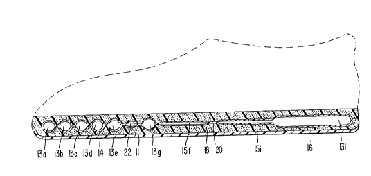
As a bladder midsole, bladder 10 defines a forefoot support 14, a heel support
16, and
a medial segment 18 interconnecting the two supports. Chambers 12 each define
a support
portion 13 and a channel portion 15. The support portions 13 are raised to
provide a resilient -
resistance force for an individual's foot. The channel portions 15 are
relatively narrow in
comparison to support portions 13, and are provided to facilitate the unique
manufacturing
process described below. Forefoot and heel supports 14, 16 are comprised
primarily of support
portions 13 so that a cushioned support is provideai under the plantar areas
receiving the greatest
impact pressure during use of the shoe. Channel portions 15, while extending
partially into the
forefoot and heel supports 14, 16, are concentrated in medial segment 18.
In forefoot support 14, the support portions 13 are arranged parallel to one
another in
a lateral direction across the sole to provide a suiW ble flexibility in the
forefront sole portion and
to apportion the cushioned resistance as desired. Nonetheless, different
chamber arrangements
could be used.
7
In the illustrated athletic shoe, forefoot portion 14 includes chambers 12a-g.
Chambers
12a-g are of varying sizes, with the chambers nearer to the front (e.g.,
chamber 12a) defining
a larger volume than those closer to medial segment 18 (e.g., chamber 12g). As
will be
described more fully below, all of the chambers 12a-g are pressurized to the
same level.
However, due to the different volumes of the: chambers, they will each possess
a unique
resistance. In other words, the chambers with smaller volumes will provide a
firmer support
than the chambers with larger volumes, because the movement of a side wall
defining a smaller
chamber will involve a greater percentage of the volume of air being displaced
than the same
movement in a larger chamber. Hence, for example, chamber 12g will provide a
firmer support
than chamber 12a.
Channel portions 15a-g of chambers 12a-~g, in general, extend rearwardly from
support
portions 13a-g to a seal 20 located transversely across medial segment 18.
Channel portions 15
are essential to the unique manufacturing process described below. Preferably,
channel portions
15 are provided along the sides of forefoot portion 14, so that the needed
cushioned support is
not taken from the central portions of the sole where it is most needed. In
the illustrated embod-
invent, channel portions 15 for adjacent chambers 12 are placed on opposite
sides of the sole.
Of course, other arrangements could be used.
Additionally, in forefoot portion 14, void chambers 22 are defined adjacent
the more
rearward chambers 12e-g. A void chamber 22 is a chamber that has not been
pressurized. Void
chambers 22 exist because of the need to limit the volume of chambers 12e-g to
provide a
certain firmness in these portions of the bladder. Nevertheless, void spaces
are not essential to
8
~ ~~~rE
the present invention and could be eliminated. In a imidsole usage (Fig. 4)
the resilient foam 11
would fill in the void space and provide ample support to the user's foot.
In a manner similar to forefoot support 14, heel support 16 includes a row of
chambers
12h-j. In the illustrated bladder, three chambers 12h-j are provided. The
support portions 13h=j
of these chambers are arranged parallel to one another in a generally
longitudinal direction
across the sole to ensure that all three chambers provide cushioned support
for all impacts to the
user's heel. Nonetheless, as with the forefoot portion, different chamber
arrangements could be
used. Additionally, each chamber 12h-j includes a channel portion 15 which
extends from the
support portion 13 to seal 20. .In the same manner as in forefoot support 14,
chambers 12h-j
provide different resistance forces in the support of the heel. For example)
the smaller chamber
12h will provide a firmer resistance than the larger chambers 12i or 12j. The
firmer chamber
12h would act as a medial post in reducing pronation.
In the first embodiment of the invention (Figure 1), chambers 12h j are
pressurized to
the same internal pressure as chambers 12a-g. One preferred example of
internal pressure for
athletic footwear is 30 psi. Of course, a wide variety of other pressures
could be used. In an
alternative embodiment of the invention (Figure :l), chambers 112h j are
pressurized to a
different internal pressure than chambers 112a-g. As one preferred example,
the pressure in the
forefoot portion could be set at 35 psi, while the heel portion could be
pressurized to 30 psi. The
particular pressure in each section though will depend on the intended
activity and the size of
the chambers, and could vary widely from the given examples.
In the fabrication of bladder 10, two elastomeric sheets 24, 26 are preferably
secured
together to define the particular weld pattern illustrated in Figure 2; that
is, that the two opposed
9
~~.~-~~3~g
sheets 24) 26 are sealed together to define wall segments 28 arranged in a
specific pattern
(Figure 2a). The welding is preferably performed. through the use of radio
frequency welding,
the process of which is well known. Of course, other methods of sealing the
sheets could be
used. Alternatively, the bladder could also be made by blow molding or
injection molding, the
processes of which are also well known.
When the bladder is initially welded (or otherwise formed), a common area 30
is defined
at the location where seal 20 is formed (Figure 2)., Common area 30 is fluidly
coupled with all
of the channel portions 15 of chambers 12a j., so that all of the chambers are
in fluid
communication with one another.
An injection pocket 32 is provided to supply bladder 10 with a quantity of
fluid.
Injection pocket 32 is in fluid communication with a pressurizing channel 34,
which, in turn)
is fluidly coupled to common area 30 (Figs. 2 and 2a). Chambers 12a j,
therefore, are
pressurized by inserting a needle (not shown) through one of the walls 24, 26
defining injection
pocket 32, and injecting a pressurized fluid therein. The pressurized fluid
flows from pocket
32, through channel 34, into common area 30, through channel portions 15a j
and into the
supporting portions 13a j of all of the chambers 12 a j . Once the
predetermined quantity of fluid
has been inserted into the bladder, or alternatively when the desired pressure
has been reached,
channel 34 is temporarily clamped.
Walls 24, 26 are welded, or otherwise heat sealed, forming seal 20 (Fig. 1 )
to cpmpletely
close common area 30 so that none of the chambers are in fluid communication
with any of the
other chambers. Although, it may in certan circumstances be desirable to
provide
interconnecting ports in other portions of the sidewalls of selected chambers.
Once sealing weld
_.
20 has been made, the needle is removed and channel 34 remains an uninflated
void area.
Hence) as can be readily appreciated ) this unique independent chamber design
can be fabricated
by the novel process in an easy, quick, and economical manner.
The fabrication of a second embodiment (Figure 3) is similar to that of the
first
embodiment (Figure 1). In particular, bladder 110 defines a forefoot support
114, a heel support
116, and a medial segment 118. The forefoot ~~nd heel supports 114) 116 each
include a
plurality of chambers 112. Specifically, forefoot support 114 includes
chambers 112a-g and heel
support 116 includes chambers 112h-j. Similarly, ~°ach chamber 112
includes a support portion
113 and a channel portion 115. Void chambers 122 are also provided to achieve
the desired
firmness in chambers 112e-g and 112h.
In contrast to the first embodiment, forefoot support 114 and heel support 116
are divided
by a sealing wall 117 across medial segment 118 prior to the supply of any
pressurized fluid.
In addition, a common area 130, 131 is defined immediately adjacent each side
of the sealing
wall 117. Common area 130 is in fluid communication with channels 115a-g, and
common area
131 is in fluid communication with channels 115h-j.
In the fabrication of bladder 110, a needle; (not shown) is inserted into each
injection
pocket 132, 133. In practice, two separate needles are preferably used,
although one needle can
be successively employed to inject fluid into each support 114, 116 if
desired. By providing two
separate injection pockets 132, 134 and sealing wall 117, different pressure
levels may be
supplied into the two separated forefoot and heel supports 114, 116. For
instance, forefoot
support 114 may be provided with a greater pressure (e.g., 35 psi) than the
pressure (e.g., 30
psi) in heel support 116, to meet the specific resisxance desired for the
intended use of the shoe.
Of course) the heel support could be provided witlh a greater pressure than
the forefoot support
if desired.
Once all of the chambers have been fully pressurized, the two common areas
130) 131
are then welded (or otherwise heat sealed) to form seals 120) 121. Seals 120,
121 function to
close the fluid communication between the chambers so that each chamber is
independent and
separate from the remaining chambers. Once the; seals have been formed the
needles can be
removed and injection pockets 132, 134 become uninflated void areas.
As can be appreciated, many different chamber configurations are possible. See
for
instance) Figure 5 which includes a significantly different weldment pattern
228 defining a
plurality a chambers 212. Like the earlier embodiments) the chambers 212 each
includes a sup-
port portion 213 and a channel portion 215. The channel portions all fluidly
interconnect the
support portions 213 with a common area 230 (Figure 6). Once the chambers have
been
pressurized by inserting a pressurizing needle in pocket 232, the common area
is sealed so that
each chamber is separated from the other chambers (Figure 5).
In another embodiment (Figure '~, the bladder 310 is designed such that the
channel
portions are eliminated. More specifically) bladder 310 is formed by a
weldment pattern 328
defining a plurality of chambers 312 comprised solely of support portions 315.
The chambers
are initially all fluidly interconnected via common area 330. Once the bladder
has been fully
pressurized, the common area 330 is sealed off to eliminate the fluid
interconnection between
the chambers (not shown).
Figure 8 illustrates a bladder 410 which ha,s been blow molded. In this
embodiment, a
plurality of chambers 412a-d are arranged into a, unique pattern. The chambers
are fluidly
12
c .e c) a ~ ~r
.~ ~./~ ~ ..j ~ g
interconnected by ports 414b-d. Of course other patterns of chambers and ports
could be used.
In any event, this embodiment does not include a common area to which each
chamber is joined.
Rather) the chambers 412 are sequentially interconnected.
Once the chambers have been formed, a netrdle is inserted into the side of
pocket 431 to
pressurize the chambers. As can be readily appreciated, the chambers 412 are
pressurized by
the fluid passing sequentially through chambers 412a-d and ports 414a-d. When
the fluid
injection is complete, the ports 414a-d are sealed to separate the chambers
from one another (not
shown). The sealing process is preferably formed :in a single step by a
specially configured die.
~ With reference to Figures 9-9c, a further embodiment of the invention is
shown, in
which, the pressure in the various chambers may be selectively varied in a
known manner in a
closed cushioning system. In Figure 9, cushioning element or bladder 510
includes four separate
gas-filled post support storage chambers 512a-d. Chambers 512 compress and
stiffen when a -
load is applied in order to provide cushioning but do not collapse upon
themselves. Forward
medial support chamber S 12b and rearward medi2~1 support chamber 512c are
disposed on the
medial side in the heel region, and extend approximately 1/3 of the width of
the bladder.
Lateral chamber 512d also is disposed in the heel region, and extends from the
medial side for
approximately 2/3 of the width of the bladder. Clhambers 512b-d are spaced
from each other.
Chambers 512b and 512c are linked by interconnecting tube or port S 14g which
may be
selectively opened or closed by pinch-off valve 518g, the operation of which
is discussed in
greater detail below. Chambers 512c and 512d ;also may be linked by port 515
to facilitate
initial pressurization of the chambers. However, ~~s shown in Figure 9 and
discussed above) if
desired, port 515 may be permanently sealed to prevent fluid flow between
chamber 512c and
13
chamber 512d. Chamber S 12a forms the forw~~rd portion of cushioning element
510, and
extends generally across the width of the sole. Chamber 512a is formed as a
separate element
from chambers 512b-d, with foam element 513 dislposed therebetween, and is not
linked directly
in fluid communication with any of chambers 512b-d. Thus, cushioning element
510 would
include separate bladder elements, although as described below, the cushioning
element could
comprise a single integrally formed bladder element.
Foam element 513 forms the arch portion of the cushioning element and includes
cylindrical openings 520x-d formed partially or fully therethrough. Variable
volume reservoir
chambers 516a-d are disposed within openings 52!)a-d, respectively. Chambers
516a-d have a
bellows shape which allows the chambers to collapse upon themselves to reduce
the volume.
Front medial reservoir chamber 516a is linked in fluid communication with
front support
chamber 512a by interconnecting tube or port 514a, and with.rear medial
compressible reservoir
516c by interconnecting tube 514c. Rear medal reservoir chamber 516c is linked
in fluid
communication with forward medial post chamber 512b by interconnexting tube
514c. Front
lateral reservoir chamber 516b is linked in fluid cornmunication with front
support chamber S 12a
by interconnecting tube 514b, and with rear lateral reservoir chamber 516d by
interconnecting
tube 514d. Rear lateral reservoir chamber 516d is further linked in fluid
communication with
lateral support chamber 512d by interconnecting tube 514f. The opening and
closing of each
of interconnecting tubes 514a-g is controlled by a corresponding valve 518x-g,
described further
below.
Cushioning is provided by the confined gas in chambers 512a-d) and any load on
any part
of a given chamber will instantaneously increase the pressure equally
throughout the whole
14
,. ,A ~ n
~.~..,~l~t.s:~~
chamber. The chamber will compress to provide cushioning, stiffening but not
collapsing, due
to the increase in pressure of the contained gas. ~Nhen open, interconnecting
tubes 514 do not
restrict the flow between support chambers 512 and reservoirs 516, and two
support chambers
and/or reservoirs connected by an open tube function dynamically as a single
chamber. Thus)
when all of tubes 514 are open) cushioning element 510 functions as a
substantially unitary
bladder providing cushioning throughout the midsole.
Valves 518 may comprise any suitable valve known in the art, for example, a
pinch-off
valve including a screw as shown in Figures 9A, 9B and 12A. With reference to
Figure 9A,
valves 518, for example, valve 518c, includes hollow rivet 522 disposed in a
hole extending
partially through foam element 513 from one end thereof. Rivet 522 includes an
indented or
blank portion 522a extending radially therethrough at the inner end. T'he
inner wall of rivet 522
is screw-threaded, and adjusting screw 524 is disposed therein. The position
of screw 524
within rivet 522b can be adjusted by rotation of the screw. In the embodiment
shown in Figures
9, screw 524 has a slotted head for this purpose) and easily may be rotated by
any flat edge
element. In the embodiment shown in Figure 12A, screw 524' includes screw cap
524a' which
extends exterior of the foam element, and preferably rests flat upon the side
of the foam element
when screw 524 is disposed fully within rivet 522. Cap 524x' allows for the
position of screw
524' to be adjusted by rotation thereof by manual manipulation without the use
of a flat-edge
object. Screws 524 preferably are made of light Wreight plastic.
Interconnecting tubes 514 are disposed within indented portion 522a. The fluid
communication may be controlled by adjusting thE: extent to which screws 524
extend within
region 522b. When screws 524 are disposed out of contact with tubes 514, the
fluid flows
.~a 2 :12 ~~ ~ ~ 8
substantially freely between reservoirs 516 and/or support chambers 512. When
screws 524 are
in the innermost position) they fully contact and pinch-off tubes 514,
preventing fluid flow
substantially completely.
As discussed, reservoirs 516a-d are disposed within cylindrical holes 520a-d
formed ~in
foam element 513. The interior of holes 520 are s,:rew-threaded and form
containing chambers
for reservoirs 516. With reference to Figure 10, flat screws 526 are disposed
in respective holes
520a-d. Downward rotation of screws 526 brings the screws into contact with
and compresses
reservoir chambers 516. Accordingly, each reservoir 516 can be adjusted to and
maintained at
a desired volume by simple rotation of the corresponding flat screw 526 which
causes the
reservoir to collapse. When reservoirs 516 are at tlheir maximum volume, the
top of screws 5 2 6
are level with the top of holes 520. Screws 526 are made of a light-weight
material such as
plastic, and may include slots 526a to allow for rotation by a flat-head
instrument. However,
due to the light-weight nature of both screws 5 2 6 chambers 518 and foam
element 513, only
a minimal downward force is needed to collapse reservoirs 516 and retain
reservoirs 516 at the
desired volume. Thus, only a minimal torque will be needed to rotate screws
526 to the desired
level. Thus, it is foreseen that adequate rotation could be provided by a
common item such as
a dime, paper clip or even the tip of the wearer's finger. If a sock liner is
provided
corresponding holes could be provided therethrough as well to provide ease of
access. With
further reference to Figure 11, holes 520' can be formed through outsole 530
to al low access
to hole 520. from below, and thus to allow reservoirs 516 to be collapsed from
below as well.
Holes 530 are screw-threaded, and screws 526 ar<: disposed therein.
16
By making use of reservoirs S 16a-d and tub<a 514, the degree of
pressurization and thus
the stiffness of each support chamber S 12a-d can be adjusted to provide
customized cushioning
at different locations of the shoe, without requiring gas to be added to or
leaked from the
bladder. For example, if it is desired to increase the resistance to
compression in the medial
rear portion of the shoe) the pressure in one or both of support chambers 512b
and 512c may
be increased in the following manner. Screw 524 of valve S 18a would be
rotated into contact
with connecting tube 514a, fully compressing the tube and preventing the flow
of gas
therethrough so as to isolate medial front reservoir '_~ 16a from support
chamber 512a. Reservoir
516a would be collapsed by rotation of the corresponding flat screw 526,
forcing gas therefrom
and into. reservoir 516c and medial support chambers 512b and 512c.
Thereafter) reservoir 516c
also would be collapsed forcing gas therefrom and into medial support chambers
512b and 512c.
Screw 524 of pinch-off valve 518e would be rotated so as to compress the
connecting tube,
isolating reservoirs 516a and 516c from support chambers 512b and 512c.
The mass of the gas in chambers 512b and 512c has been increased, and since
chambers
512b and 512c are now isolated from the other support chambers of the bladder,
their effective
volume is reduced. Thus, the pressure in chambers 512b and 512c is increased.
As a result,
when chambers 512b and 512c are loaded, element 510 has an increased
resistance to
compression and is stiffer at the location of support chambers 512b and 512c.
If desired, the
resistance to compression of chambers 512b and 512c can be further increased
by closing tube
514c, making the chambers independent of each other and decreasing their
effective volumes
further. Thus, when a load is localized at one or the other of chambers 512b
or 512c, the
stiffness of the loaded chamber is increased since g;as flow to the other
chamber is prevented.
17
For most people) during walking or running the foot rolls forwardly from the
heel. Thus,
chamber 512c experiences maximum loading separately from chamber 512b. As the
foot rolls
forwardly, the stiffness of each chamber is increased as it receives the
maximum load beyond
the maximum stiffness when the chambers are in communication. Accordingly, the
overall
stiffness experienced by the wearer is increased.
The pressure in both of chambers 512b and :i 12c could be further increased by
reopening
interconnecting tube 514a and rotating flat screws 526 into their uppermost
position to allow
additional gas to flow from support chamber 512a into collapsible reservoirs
516a and 516c.
The process described above is then repeated to forcx the gas from reservoirs
516a and 516c into
chambers 512b and 512c to further increase their stiffness. This process can
be completed until
any desired stiffness is obtained. In a similar manner, the effective volumes
of chambers 512a
and/or 512d can be adjusted by performing similar manipulations on reservoirs
516b and 5164.
In fact) by making use of all four reservoirs 51 fi, gas may be transferred
from any one of
chambers 512 to any of the other chambers to increase or decrease the
stiffness of the bladder
at a desired location) to thereby tune the overall cushioning characteristics
of the midsole for
a particular activity or for a specific gait characteristic of the wearer. For
example, a wearer
who tends to strike the ground at the midfoot or tree forefoot may prefer that
forefoot chamber
512a be more compliant. In this case, the fluid pressure could be transferred
to the three
rearward chambers. Similarly, a wearer who strikes the ground at the lateral
rear may prefer
that chamber 512d be less resistant and that forefoot chamber 512a be more
resistant, in which
case the fluid pressure could be transferred to chamber 512a from chamber
512d.
18
~~~~~~8
Furthermore) the overall pressure in chambers 512a-d and thus element 510 as a
whole,
can be reduced by pumping and storing gas into reservoirs 516a-d. For example)
connectors
514a, 514b, 514e and 514f could be closed to isolate reservoirs S 16a-d from
support chambers
512a-d. Reservoirs 516a-c could be compressed to force fluid into reservoir
516d. Thereafter,
connector 514d could be closed to isolate reservoir 516d. Reopening connectors
514a, 514b and
514e and allowing reservoirs 516a-c to expand by rotating flat screws 526 into
their uppermost
positions would lower the pressure in support chambers 512a-c. The process
could then be
repeated for reservoir 516c to further lower the overall pressure in bladder S
10.
Although as shown in Figure 9, cushioning element 510 includes two separate
bladder
elements, that is, chamber 512a is formed as a separate element from chambers
512c-d)
cushioning element 510 could be a single integral element in which chamber
512a could extend
rearwardly to the forward boundary of chambers 512b and 512d, with foam
element 513
eliminated. However, the portion of chamber 512a~ which would be disposed in
the arch area
of the shoe would be thinner than the remainder of chamber 512a, so as to
allow pinch-off
valves 518 to be disposed either above or below chamber 512x, and would
include cylindrical
holes formed therethrough for placement of reservoir chambers 516. Separate
wall elements
having internal threading could be disposed in the holes to allow for the use
of flat screws 526.
In this construction, chaunber 512a would still be isolated by an internal
wall from fluid
communication with chambers 512b and 512d. Of course, bladder 510 could be
formed as a
single element) including reservoirs 516.
The present invention provides for an infinite: number of vau-iations of
pressure and thus
stiffness at various locations in the midsole, without requiring that gas be
supplied to or released
19
~~.~~~;~o
from the bladder. That is, the variations in pressure are achieved in a closed
system. Thus, the
attendant drawbacks of open air systems such as leakage or the requirement for
an external pump
are avoided. It is preferred that reservoir chambers 516 be placed in the arch
or midfoot area
as shown. This area receives relatively low loads and a closed reservoir in
this location which
would yield limited cushioning would not pose a problem) especially where foam
element 513
is used. However, it is possible to locate the reservoirs at any convenient
location, even outside
of the midsole such as on the upper. Although one particular configuration of
the various
support chambers and reservoirs is shown, other configurations could be used.
For example)
chamber 512a or 512d could be broken into several smaller chambers linked in
fluid
communication by interconnecting tubes.
With reference to Figures 12) 12a and 12b, an alternative embodiment of the
invention
disclosed in Figures 9-11 is shown. Cushioning unit 600 includes heel support
cushion 602 and
collapsible reservoir chamber 604, linked in fluid communication by
interconnecting tube 606a.
Pinch-off valve 608a is disposed to control the opening and closing of tube
606a. Heel cushion
602 includes main chamber 602a) and medial post chamber 602b linked thereto by
interconnecting tube 606b. Pinch-off valve 608b is disposed to control the
opening and closing
of interconnecting tube 606b. Reservoir chamber 6C~4 has a bellows shape and
may be collapsed
to vary the contained volume thereof. Although not shown) the volume of
reservoir chamber
604 could be adj usted and fixed in the same manner as reservoirs 516 in
Figures 9-11, that is,
by the use of flat screws.
When reservoir chamber 604 and heel cushion 602 are in full communication,
that is,
when interconnecting tube 606a is fully opened, the; overall effective volume
of the unit is the
__
sum of the volumes of both chamber 604 and heel, cushion 602. By compression
of reservoir
chamber 604, the gas contained in reservoir 604 is pumped into heel cushion
602. If tube 606a
is closed, the overall effective volume of the unit is decreased to that of
heel cushion 602.
Thus, the resistance to compression of heel cushion 602 is increased)
providing more stiffness
at the heel of the shoe. In a preferred embodiment, the volume of chamber 604
when fully
expanded is half of the volume of heel cushion 602. Thus, if chamber 604 is
compressed fully)
the effective pressure of heel cushion 602 is increaised 1.5 times. For
example, if the starting
overall pressure of unit 600 and thus, of heel cushion 602 is 20psi, the
pressure in heel cushion
602 would be increased to 30 psi by fully compressing chamber 604.
Additionally, since the
overall volume of unit 600 is decreased by one third when chamber 604 is
compressed fully, the
combined effect is to further stiffen heel cushion 632. Of course, the
pressure in heel cushion
602 can be increased to a lesser extent by only partially compressing chamber
604. The
pressure in heel cushion 602 can be increased further if interconnecting tube
606b is closed
before compression of chamber 604 so that none of the gas in chamber 604 flows
into post
chamber 602b.
If desired, the pressure in medial post chamber 602b can be increased beyond
that of
main chamber 602a of heel cushion 602 by collapsing chamber 604, and then
isolating post
chamber 602b from main chamber 602a by closing tube 606b. If tube 606a is not
closed, then
the overall effective volume of main chamber 602a, which remains in
communication with
reservoir chamber 604 will only be reduced by the volume of post chamber 602b.
Further, the
mass of fluid contained in post chamber 602b will lbe increased. Since the
volume of chamber
602b is significantly smaller than that of chamber ~602a, the pressure in
chamber 602a will be
?1
reduced slightly, while the pressure in chamber 602b will be increased
greatly. Thus, heel
cushion 602 will be stiffer at chamber 602b than at the remaining portion
thereof.
In the embodiments of Figures 9-12, it is preferred that the units be
manufactured by
vacuum-forming or blowmolding. Radio frequency welding of sheet film to form
the bladder
would also work. The preferred film is polyester polyurethane manufactured by
Tetra Plastics.
The preferred inflatant fluid is sulfurhexafloride gas SF6; however, any gas
or combination of
gases will work.
22