Note: Descriptions are shown in the official language in which they were submitted.
. . .,..,~i...n~, r.
CA 02124446 2004-12-08
1
DRAG EMBEDMENT MARINE ANCHOR
The present invention relates to drag embedment
marine anchors.
A requirement of a drag embedment marine anchor
comprising a fluke attached to a shank is an ability to
dig deeply into a mooring bed. The holding capacity is
directly related to depth of embedment below the surface
of the mooring bed. The ability to dig into the mooring
bed soil depends on the anchor having a fluke angle
appropriate for the particular soil present in the mooring
bed. The fluke angle is usually defined as the angle
between the forward direction of the fluke and a line
cor_necting the anchor cable attachment point on the shank
to a point on the rear edge of the fluke measured in a
fore-and-aft plane of symmetry of the anchor. ~n
practice, this angle is about 50° for muds 'and about 30°
for sands. The angle that a straight line containing the
cable attachment point and the centroid of the fluke forms
with the forward direction of the fluke. is correspondingly
in the range 60° to 70° for muds and 35° to 45°
for sands
where the fluke is of triangular or rectangular shapes
with a length to breadth ratio in the usual range between
1 and 2. This latter angle may be regarded as the
centroid fluke angle.
The angle of friction, , between a marine soil and a
smooth steel anchor fluke is usually in the range 22° to
30° for sand and 6° to 14° for mud. Thus, the centroid
fluke ancdle is always made less than (90-~y degrees to
ensure that a pulling force applied at the anchor cable
attachment point causes the anchor to penetrate by sliding
in the soil in the fon~~rard direction of the fluke and so
bury increasingly below the surface of the mooring bed
wizen pulled horizontally thereon.
A deeply buried marine drag embedment anchor is
usually recovered by heaving vertically upwards on the
anct-.c~r cable attached to the forward end of the anchor
WO 93/11028 2 ~ 2 4 4 4 6 PCT/GB92/02210
2
shank or by heaving vertically upwards on a pendant cable
attached to the anchor at the rear edge of the fluke.
This vertical pull first rotates the anchor in the soil
until the centroid of the fluke lies vertically below
either the cable attachment point on the shank (referred
to as the break-out position) or the pendant cable
attachment point at the rear edge of the fluke. When
heaved up by the anchor cable, following rotation, the
anchor simply continues "digging~ in the forward direction
of the fluke but obliquely to the vertical instead of
obliquely to the horizontal until it emerges from the
surface of the mooring bed. When heaved up by the pendant
cable, following rotation, the anchor moves vertically
upwards in the soil since she vertical cable dies in the
rotated direction of the fl~fe.
The breaking-out force is least when heaving up by
the pendant cable and grEates~ when heaving up by the
anchor cable. Peak breaking-out force occuYs in the
anchor cable immediately f~=low=.?g rotation of the anchor
and just before movement oblique to the vertical occurs.
This peak breaking-out force ir~ the anchor cable usually
has a magnitude of approx_mate_y 20 to 30 per cent of
prior peak horizontal embea.~nent =orce in sands and of the
order of 100 per cent in mulls. generally, minimisation of
anchor breaking-out force is, ir_ter alia, an objective of
drag embedment anchor design.
In contrast, it is an object of the present invention
to provide a drag embedment marine anchor and a method
wherein the breaking-out force at the break-out position
is maximised. It is ar_othe= object of the present
invention to provide a drag embedment marine a..~.chor and a
method wherein the holding capacity may be increased at a
given depth of embedment in a mooring bed soil.
Yet another objective of the present invention is to
provide a method of limiting the load developed by a
marine anchor during drag embedment to permit dragging to
a desired location at constant load prior to increasing
the holding capacity at such desired location.
SUBSTITUTE SHEET
~,.,.. ~ T
r . .~__ ...
212 ~ 4 4 6 ._ _ p~~'~0~ ~ 210 2 210
~_ ...._~°:~~~1
3
These objectives are met, in accordance with the
present invention, by providing an anchor which embeds in a
mooring bed soil when pulled at an anchor cable attachment
point at a relatively small fluke centroid angle and which
can be subsequently pulled at an anchor cable attachment
point at a larger fluke centroid angle whereby movement of
the anchor in the direction of the fluke against friction is
substantially prevented.
According to the present invention, a marine anchor for
drag embedment in a submerged soil comprises a marine
anchor for drag embedment in a submerged soil compriosing a
fluke (8) and a shank means (3) attached at an extremity of .
said shank means (3) to the fluke (8), and arranged to
provide at least one attachment point (4A/4B) for attachment
of an anchor cable (64), characterised in that the anchor is
arranged to provide first and second directions (5, 6)
respectively from the fluke centroid (7) whereby, in
relation to the forward direction (F) of the fluke (8)
measured in a fore-and-aft plane of symmetry (M-M) of the
anchor, said first directions (5) forms a first forward
opening angle (oC) with said forward direction (F) and said
second direction (6) forms a second forward opening angle
with said forward direction (F) greater than said first
orward opening angle (0C) so that the projected area of the
fluke (8) in said second direction (6) is greater than the
projected area of the fluke (8) in said first direction (5)
whereby a first pulling action on the anchor at an
attachment point (4A) located in said first direction (5)
permits drag embedment of the anchor by movement
substantially in said forward direction (F) in the soil
whilst a subsequent pulling action on the embedded anchor in
said soil at an attachment point (4B) in said second
direction (6) precludes such movement -
Preferably, the first and second forward-opening angles ___.
are chosen with regard to the angle of friction, ~, between
the fluke surface and the marine soil in which the anchor is
to be embedded, whereby the first forward-opening angle is
,~M.;.,.;,~ r.-.. ...;~~N;;,~ -,.::~.:-.. . :~~ - ~~~5 ~ ~T~T~ SHEET
F(yl, L:li:f::~::~~;~::~ ;r ~t,'~.I~il
i
CA 02124446 2004-12-08
4
less than 90-sa degrees and the second forward-opening angle is
in the range 90 ~ r~ so that embedment occurs when the anchor
is pulled horizontally by the cable and horizontal slippage is
prevented when the fluke is finally horizontal and the anchor
is pulled vertically by the cable.
It is further preferred that the second forward-opening
angle lying in the range 90 ~ s~ more particularly, lies in the
range 84 to 96 degrees for mud operation and 68 to 112 degrees
for sand operation.
According to one embodiment of the present invention
there is provided a marine anchor for drag embedment in a
submerged soil comprising a fluke (8) and a shank means (3)
attached to the fluke (8) and arranged to provide at least one
attachment point (4A/4B) for attachment of an anchor cable
(64), characterised in that means (4A,4B) are provided for
attaching first and second anchor cables to the anchor so as
to lie in first and second direction (5, 6) respectively from
the fluke centroid (7) whereby, in relation to the forward
direction (F) of the fluke (8) measured in a fore-and-aft
plane of symmetry (M-M) of the anchor, said first direction
(5) forms a first forward-opening angle (a) with said forward
direction (F) and said second direction (6) forms a second
forward-opening angle (~i) with said forward direction (F)
greater than said first forward-opening angle (a) so that the
projected area of the fluke (8) in said second direction (6)
is greater than the projected area of the fluke (8) in said
first direction (5) whereby a first pulling action on the
anchor via said first anchor cable at an attachment point (4A)
located in said first direction (5) permits drag embedment of
the anchor by movement substantially in said forward direction
(F) in the soil whilst -a subsequent pulling action on the
embedded anchor in said soil via said second anchor cable at
i i1 ~ -I ,. I
CA 02124446 2004-12-08
4a
an attachment point (4B) in said second direction (6)
precludes such movement; in that at least a portion of said
shank means (3) to which said first anchor cable is attached
is releasable from the anchor, and in that remotely operable
release means (46, 48) are provided for release of said shank
portion following drag embedment of the anchor.
According to another embodiment of the invention a
marine anchor for drag embedment in a submerged soil
comprising a fluke (8) and a shank means (3) attached to the
fluke (8) arranged to provide at least one attachment point
(4A/4B) for attachment of an anchor cable (64), characterised
in that at least a portion of said shank means (3) is
pivotable about a pivot axis (16) located in the anchor
transverse to said plane of symmetry (M-M), so that said
anchor cable attachment point is movable between first and
second directions (5, 6) from the centroid (7) of the fluke
(8) such that in relation to the forward direction (F) of the
fluke (8) measured in a fore-and-aft plane of symmetry (M-M)
of the anchor, said first direction (5) forms a first forward-
opening angle (a) with said forward direction (F) and said
second direction (6) forms a second forward opening angle ((3)
with said forward direction (F). greater than said first
forward opening angle (a), so that the projected area of the
fluke (8) in said second direction (6) is greater than the
projected area of the fluke (8) in said first direction (5),
whereby a first pulling action on the anchor via said anchor
cable (64) at an attachment point (4A) located in said first
direction (5) permits drag embedment of the anchor by movement
substantially in said forward direction (F) in the soil whilst
a subsequent pulling action on the embedded anchor in said
soil via said anchor cable (64) at an attachment point (4B)
located in said second direction (6) precludes such movement,
i i1 ~ I i , I
CA 02124446 2004-12-08
4b
in that remotely operable means (26, 29) are provided to
enable selective movement of said anchor cable (64) from said
first direction (5) into said second direction (6), and in
that said pivot axis (16) is located in the vicinity of or aft
of a straight line (5) containing the fluke centroid (7) and
the anchor cable attachment point (4A) lying in said first
direction (5).
According to a further embodiment of the invention a
marine anchor for drag embedment in a submerged soil
comprising a fluke (8) and a shank means (3) attached to the
fluke (8), and arranged to provide at least one attachment
point (4A/4B) for attachment of an anchor cable (64)
characterised in that at least a portion of said shank means
(3) is pivotable about a pivot axis (16) located in the anchor
transverse to said plane of symmetry (M-M) so that said anchor
cable attachment point is movable between first and second
directions (5, 6) from the centroid (7) of the fluke (8) such
that in relation to the forward direction (F) of the fluke (8)
measured in a fore-and-aft plane of symmetry (M-M) of the
anchor, said first direction (5) forms a first forward-opening
angle (a) with said forward direction (F) and said second
direction (6) forms a second forward opening angle (~3) with
said forward direction (F) greater than said first opening
angle (a), so that the projected area of the fluke (8) in said
second direction (6) is greater than the projected area of the
fluke (8) in said first direction (5), whereby a first pulling
action on the anchor via said anchor cable (64) at an
attachment point (4A) located in said first direction (5)
permits drag embedment of the anchor by movement substantially
in said forward direction (F) in the soil whilst a subsequent
pulling action on the embedded anchor in said soil via said
anchor cable (64) at an attachment point (4B) located in said
i il . I a I
CA 02124446 2004-12-08
4c
second direction (6) precludes such movement, in that remotely
operable means (26, 29) are provided to enable selective
movement of said anchor cable (64) from said first direction
(5) into said second direction (6), in that the anchor
includes first restraint means (26) to restrain the shank (3)
such that the anchor cable attachment point lies in said first
direction (5) during drag embedment of the anchor, and first
restraint release means (29) whereby the restraint means (26)
can be released to permit pivoting of said shank (3) to occur
to allow the anchor cable attachment point (4A) to be moved
into said second direction (6) by pulling on the anchor cable
(64) following completion of embedment of the anchor, and in
that said first restraint means (25) is located at the same
side of a straight line (5) containing the fluke centroid (7)
and the anchor cable attachment point (4A) lying in said first
direction (5) as said pivot axis (16).
According to a further embodiment of the invention a
marine anchor for drag embedment in a submerged soil
comprising a fluke (8) and a shank means (3) attached at an
extremity of said shank means (3) to the fluke (8), and
arranged to provide at least one attachment point (4A/4B) for
attachment of an anchor cable (64) characterised in that means
(4A, 4B) are provided for attaching first and second anchor
cables to the anchor so as to lie in first and second
directions (5, 6) respectively from the fluke centroid (7)
whereby, in relation to the forward direction (F) of the fluke
(8) measured in a fore-and-aft plane of symmetry (M-M) of the
anchor, a first direction (5) forms a first forward-opening
angle (a) with said forward direction (F) and a second
direction (6) forms a second forward-opening angle ((3) with
said forward direction (F) greater than said first forward-
opening angle (a) so that the projected area of the fluke (8)
i I - ~. ..... . II i1 r J I n , 1
CA 02124446 2004-12-08
4d
in said second direction (6) is greater than the projected
area of the fluke (8) in said first direction (5) whereby a
first pulling action on the anchor at an attachment point (4A)
located in said first direction (5) permits drag embedment of
the anchor by movement substantially in said forward direction
(F) in the soil whilst a subsequent pulling action on the
embedded anchor at an attachment point (4B) in said second
direction (6), direction (F) precludes such movement and in
that the projection of said shank means (3) orthogonally on to
a straight line lying in the forward direction (F) is
substantially located aft of a foremost extremity (9) of the
fluke (8) .
According to a further embodiment of the invention a
marine anchor for drag embedment in a submerged soil
comprising a fluke (8) and a shank means (3) attached at an
extremity of said shank means (3) to the fluke (8), and
arranged to provide at least one attachment point (4A/4B) for
attachment of an anchor cable (64), characterised in that the
anchor is arranged to provide first and second directions (5,
6) respectively from the fluke centroid (7) whereby, in
relation to the forward direction (F) of the fluke (8)
measured in a fore-and-aft plane of symmetry (M-M) of the
anchor, said first directions (5) forms a first forward
opening angle (a) with said forward direction (F) and said
second direction (6) forms a second forward opening angle ((3)
with said forward direction (F) greater than said first
forward opening angle (a) and substantially normal to the
fluke (8) so that the projected area of the fluke (8) in said
second direction (6) is greater than the projected area of the
fluke (8) in said first direction (5) whereby a first pulling
action on the anchor at an attachment point (4A) located in
said first direction (5) permits drag embedment of the anchor
- , i .,..., ..n.... a~,. ,.
CA 02124446 2004-12-08
4e
by movement substantially in said forward direction (F) in the
soil whilst a subsequent pulling action on the embedded anchor
in said soil at an attachment point (4B) in said second
direction (6) precludes such movement.
According to a further embodiment of the invention a
method of controlling the load developed by a marine anchor
having a shank (3) and fluke (8) during drag embedment when
pulled in a mooring bed by an anchor cable (64) attached
thereto characterised by:
(a) attaching a control pendant cable (65) to a portion of
the anchor shank (3) or to a rearward portion of the anchor
cable (64.) attached to said shank to enable rotation of the
anchor to reduce the angle of inclination of the fluke to the
horizontal;
(b) laying out the anchor (1) on the mooring bed and
pulling horizontally on the anchor cable (64) to cause
embedment of the anchor (1) into the mooring bed;
(c) measuring the load developed in the anchor cable (64)
as embedment progresses;
(d) pulling upwards on the control pendant cable (65) when
the anchor cable load reaches a designated magnitude and
maintaining a force in the control pendant cable (65)
sufficient to rotate the moving anchor (1) and reduce the
angle of inclination to the horizontal of the anchor fluke and
so reduce the holding capacity of the anchor (1);
(e) noting the effect of the control pendant force on the
measured load in the anchor cable (64);
(f) varyinq the force in the control pendant cable (65) in
accordance with the noted effect to control the anchor cable
load to a constant designated value as the anchor is dragged
to a desired installation location.
I n n.i.. . i1 n r .J i .
CA 02124446 2004-12-08
4f
According to a further aspect of the present invention,
a method of controlling the load developed by a marine anchor
during drag embedment when pulled in a mooring bed by an
anchor cable attached thereto involves:
(a) attaching a control pendant cable to a portion of the
anchor shank or to a rearward portion of the anchor cable
attached to said shank to enable rotation of the anchor to
WO 93/ I 1028 2 ~ 2 ~ ~ 6 PCT/G 892/02210
reduce the angle of inclination of the anchor to the
horizontal;
(b) laying out the anchor on the mooring bed and pulling
horizontally on the anchor cable to cause embedment of the
anchor into the mooring bed;
(c) measuring the load developed in the anchor cable as
embedment progresses;
(d) pulling upwards on the control pendant cable when the
anchor cable load reaches a designated magnitude and
maintaining a force in the control pendant cable
sufficient to rotate the moving anchor and reduce the
angle of inclination to the horizontal of the anchor fluke
and so reduce the holding capacity of the anchor;
(Gi noting the effect of the control pendant force on the
maasured load in the anchor cable;
(f) varying the force in the control pendant cable in
accordance with the noted effect to control the anchor
cable load to a constant designated value as the anchor is
dragged to a desired installation location.
Preferably said control pendant cable is attached by
remotely releaseable attachment means whereby said control
r~endant cable may be released and recovered following
lIlStallation of the anchor.
Preferably the marine anchor employed in the above
method is constructed according to the present invention.
Embodiments of the present invention will now be
described by way of example with reference to the
accompanying drawings wherein:
Fig 1 is a side view of a marine anchor in accordance
with a first embodiment of the present invention;
Fig 2 is a plan view of the anchor in Fig 1;
Fig 3 is a front view of the anchor in Fig 1;
Fig 4 shows a section P-P through a releasable
coupling in the anchor in Fig 1;
Fig 5 shows the coupling of Fig 4 released;
Figs 1A to 3A show similar views to Fig 1 to 3 for a
modified anchor;
SUBSTITUTE SHEET
WO 93/ 11028 1 ~ ~ ~ 6 PCT/G B92/02210
Figs 6 to 8 show similar views to Figs 1 to 3 for a
second embodiment of the present invention;
Figs 9 to 11 show similar views to Figs 1 to 3 for a
third embodiment of the present invention including a
pivoting anchor shank;
Fig 12 shows positions of parts of the anchor in Figs
9 to 11 following operation of a shank pivot release
mechanism;
Fig 13 shows an alternative pivot stop mechanism for
the anchor in Figs 9 to 11; and
Fig 14 shows a pictorial view illustrating operation
of the invention.
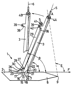
Referring to Figs 1 to 5, a marine anchor 1 is
symmetrical about a fore-and-aft plane M-M and comprises a
fluke 2, a shank 3 attached to the fluke 2 adjacent the
centroid 7 of the fluke and including a first anchor cable
attachment point 4A comprising a hole at the shank end A
furthest from the fluke 2, and a second anchor cable
attachment point 4B at the outer end of a slotted hole at
an aft position B on the shank between shank end A and
fluke 2. Holes 4A, 4B serve to receive the pin of a
shackle for attachment of an anchor cable. Fluke 2
comprises two fluke halves, 8, each of generally
pentagonal shape in plan view with a foremost point 9
spaced from the plane of symmetry M-M. In front view, the
planar upper surface of each half fluke forms an angle 8
in the range 60 to 90 degrees with the plane of symmetry
M-M. The ratio of length to width of the fluke in plan
view is preferably in the range 1 to 2.
The forward direction F of the fluke 2 is defined by
the line intersection of planar surfaces 10 with the plane
of symmetry M-M and in the sense of moving from centroid 7
to point 9 in Fig 1. The centroid fluke angle o~ (the
first centroid fluke angle) is the angle between the
forward direction F of fluke 2 and a straight line 5
containing centroid 7 and cable attachment point 4A and is
less than (90 - ~) degrees, where ~ is the angle of
friction between the anchor and the soil in which it is to
SUBSTITUTE SHEET
~ ~ _w_. _
",.." ..~i", a~... ~,
CA 02124446 2004-12-08
7
be embedded. The magnitude of ~ is taken to be 30 degrees
for sands and 15 degrees for muds for the purpose of
determining o~ . Angle ~ is shown as about 70 degrees
(for mud) in Fig 1, i.e. less than 75 degrees. The fluke
point angle 8 is the angle between the forward direction F
of fluke 2 and a straight line containing the first cable
attachment point 4A and the projection of fluke 'points 9
in the plane of symmetry M-M .and is in the range 90
degrees to 110 degrees for soft mud and 50 degrees to 70
degrees for sand:. Angle $, is shown as 100 degrees in. Fig
1 for mud.
The .straight line 6 containing the fluke centroid 7
and the second cable attachment point 4~B fornns an angle Q
(the second centroid fluke angle) with the forward
direction F of tire fluke in the range (90 ~ ø~) degrees_
Angle ~S is shown ns 90 degrees for both mud and sand in
Fig 1_ The attacn.ment point aB is spaced 25 t.c 100 per
cent of the flu~:e length above the fluke to prevent'
rotational instability of the fluke 2 about point 4Fs due
to anv soil pressure distribution variations over the
fluke.
Shank 3 is of plate construction- of thickness less
than 5 per cent of the fluke width andbevelled on the
forward edge to minimi s~ resistance to penetration of the
shank into a mooring bed soil _ In side view, the shank 3
is of Y-shape with a longer upper limb 3A inclined
approximately at angle o~ to direction F and a shorter
upper limb 3B inclined at angle L to direction F and with
a short lower limb 3C o= the Y-shape attached to fluke 2.
adjacent the fluke cen~.roid 7. In front view, the fluke 2
has maximum depth of section in the plane of symmetry M-M
and minimum depth of section distal to M-M, being .of
gene~raily wedge-shape at each side of M-M and being hollow
double-skinned plate construction of minimum frontal
cross-sectional area to minimise resistance to penetration
in the soil in direction F_ Overall, the ratio of plate
area of the anchor to area of the anchor projected in
direction F is maximised consistent with preserving
~ I. " n.~~ II W V-i.. V ~
CA 02124446 2004-12-08
8
adequate structural strength so that resistance to motion
in direction F is as small as possible whilst resistance
to movement at right angles to direction F is as large as
possible.
Shank limb 3A is removably mounted on shank limb 3B
by means of a pair of lugs 43 attached to the end of limb
3A remote from end A. Lugs 43 are spaced to _fit one at
each side of limb 3B and have coaxial holes 44 which align
axially with a hole 45 in limb 3B to form a clevis-and is
pinned to limb 3B by means of two cylindrical pins 46
(Figs 4 and 5)_ Pins 46 abut against two pistons 47
fitted with oils seals 48 and lying back-to-back abutting
against each other in plane M-M at the centre of hole 45 _
The pistons 47 have facing bevels a9 which form an annular
oil chamber fed by oil through drilled oil-way 50
connected to oil supply pipe 51. Pin travel sops 52 are
bolted onto lugs 43 to stop extrusion of pins ~ by oil
pressure in hole 45 when the abutting faces 53 between
pins 46 and pistons 47 are aligned with the outer surfaces
of limb 3B. 'Faces 53 are adhesively held together by
means of a low shear strength adhesive such as epoxy resin
which. shears when a small load is applied by pulling on
the first anchor cable attachment point 4A when faces 53
are in alignment with the outer surfaces of limb 3B.
Shank limb 3B is fitted with a slideable sleeve 54'
having a hole 55 to receive a pin 56 ~of a shackl a 57 for
attachment of an anchor cable thereto. Hole 55 is
positioned to co-opera'e with slotted hole 4B such that
pin 56 passing through hole 55 and dotted hole 4B hGs a
range of sliding movement, carrying sleeve 54 with it,
defined by the slotted hole 4B_ Coaxial holes 58 are
present in sleeve 54 and limb 3B to receive a shearable
pin 59 which locks sleeve 54 in the position wherein pin
55 is located at the e:~d of slotted hole 4B nearest fluke
2. A pulling force exceeding the shear failure load of
shearable pin 59 in a direction at Yight tingles to
direction F will shear pin 59 and move pin 55 (and so
sleeve 54) away from fluke 2 by the travel allowed by
l..",.", ..n"~ n,.. w,
CA 02124446 2004-12-08
9
slotted hole 4B. A lug 60 is attached to the aft face of
sleeve 54 and a similar lug 61 is attached to the aft face
of limb 3B. An oil-filled hydraulic cylinder 62 is
connected to lug 60 with its piston. rod connected to lug
61. Cylinder 62 is connected by oil supply pipe 51 to the
drilled oil-way 50 in limb 3B whereby movement of pin 55
along slotted hole 4B following shearing of pin 59
actuates cylinder 62 and pumps oil'into hole 45 between
pistons 47. This extrudes pins 46 from hole 45 and allows
limb 3A to be pulled away from limb 3B on shearing of the
adhesive between.abutting faces 53 to permit recovery of
limb 3A and the anchor cable attached thereto_ An
alternative arrangement is envisaged where the pin
extrusion mechanism is 1 ocated at attach_Inent point 4A and
in an anchor shackle attached theretc.
In this case, limb 3A would.not be recovered with the
anchor cable and would be constructed simply as an
integral part of shankW .
Yet another arrangement i's envisaged (see Figs 1A to
3A) wherein the complete release mechanism for .releasing
the anchor cable attached to point 4A is deleted and
points 4A and 4B have only round holes for receiving
shackle pins. in this arrangement, limbs 3A and 3B are
integral .parts of shank 3 and a shearablE shackle pin at
point 4A permits recovery. of a first anchor cable.
In the embodiment of Figs 6 to S, the second anchor
cable,attachment point ~B is separated from the fluke by
approximately one length cf the fluke and connected to the
first.anchor cable attachment point 4A by a slot 11 in the
shank 3 so that sliding movement of .. a shackle pin therein
can transfer an anchor cable attached thereto from point
4A to point 4B. The axis of slot 11 intersects the centre
of a shackle pin hole at paint 4A but intersects a shackle
pin hole at point 4B offset towards fluke 2 so that the
shackle pin can lodge under load in the hole at point 4B.
Generally, the anchor corresponds to the anchor shown in
Figs 1 to.3 and like parts carry like references. Shank 3
is of triangular shape in side view with a triangular
i i
WO 93/11028 1
PCT/GB92/02210
~~O
aperture 12 therein to reduce weight. A lug 13 having a
hole 14 is attached to shank 3 adjacent anchor cable
attachment point 4B to receive a shackle pin for
attachment of an anchor pendant cable thereby. The anchor
of figs 6 to 8 will probably be more suited for lighter
load applications eg for yachts and small boats.
In the embodiment of Figs 9 to 13, the first anchor
cable attachment point 4A is physically moveable by virtue
of shank 3 being rotatable about pivot 15 in the fluke 2
so that point 4A can move out of line 5 into line 6 to
become point 4B corresponding to point 4B in Fig 4. The
anchor corresponds to the anchor shown in Figs 1 to 3 and
like parts carry like references. Pivot 15 has an axis 16
normal to the plane of symmetry M-M and located in the
fluke 2 aft of fluke centroid 7 below planar surfaces 10.
A pivot pin 17 serves to locate lug 18, comprising the end
of shank 3 remote from end A, between two lugs 19 attached
to the underside of the fluke. Shank 3 passes through
aperture 20 in fluke 2 with a forward edge 21 of the
aperture 20 abutting against the forward edge 22 of shank
3 which edge 21 serves as a stop to stop rotation of the
shank 3 form forming a fluke centroid angle ~ less than
that given for the embodiment of Figs 1 to 3.
A rearward edge 23 of aperture 20 and a stop 24
attached to fluke 2 can abut against a rearward edge 25 of
shank 3 to stop rotation of shank 3 from forming an angle
Q great than that given for the embodiment of Figs 1 to 3.
A wedge-shaped stop 26 bearing a pin clevis 27 and pin 28
is removably interposed between edge 25 of shank 3 and
stop 24 to lock shank 3 temporarily with point 4A in line
5. A stop removal lever 29 is pivotably attached at one
end by pin 28 to clevis 27 on wedge-stop 26 and laid off
lengthwise along rear edge 25 of shank 3. A toe 30 is
formed on lever 29 adjacent pin 28 which can bear on stop
24 following rotation of lever 29 away from shank edge 25
and in turn act as a fulcrum for further rotation of lever
29 to prise wedge-stop 26 forcibly out of its position
between stop 24 and edge 25 to permit shank 3 to rotate
SUBSTITUTE SHEET
~ T . .. .. .
WO 93/11028 2 '~ ~ ~ ~ 6 PCT/GB92/02210
y~ I
into abutment with stop 24 and so bring point 4A out of
line 5 into line 6. A spring loaded wedge stop (not
shown) under the fluke is now free to move up between edge
21 and edge 22 to lock shank 3 with point 4A at location
4B in line 6. An alternative stop and locking arrangement
for shank 3 is shown in Fig 13 wherein a crank arm 31 is
provided which bears on fluke plate 32 under stop 24 to
restrict forward rotation of shank 3 instead of edge 22
bearing on edge 21. A role 33 is provided at the
extremity of arm 31 which aligns with a corresponding hole
34 in lugs 19 when shank 3 rotates to bring edge 25 into
abutment with stop 24. A spring loaded bolt 35 is mounted
in hole 34 in one of lugs 19 which threads hole 33 when
aligned with holes 34 to lock shank 3 to lugs 1~ witr tha
anchor cable attachment point 4A in position 4B (Figs _2
and 13) and lying in line 6. Another hole 35 in arm 31 is
provided which is in initial alignment wit.: corresponding
coaxial holes in lugs 19. A shearable ein 37 may be
fitted in hole 36 to lock shank 3 to lugs 19 when point 4A
is initially in line 5 whereby exceeding a designated
moment of force about pivot axis 16 shears pin 37 and sc
allows shank 3 to rotate rearwards.
Shank 3 has clevis lugs 38 with coaxial holes
located on the rear edge 25 spaced approximately 20 per
cent of the shank length from point 4A. Lever 29 (Figs 12
and 13) has a length of 0.8 times the length of shank 3
and has a lug hole 41 at an end remote from toe 30 to
receive a shackle pin for connection thereto of an anchor
pendant cable. Lever 29 also has a hole 40 for coaxial
registration between lugs 38 with holes 3°. A shearable
pin 42 is fitted through holes 39 and 40 which is
breakable by a designated force applied at hole 41 by
pulling up on the anchor pendanr_ cable. Further pulling
up on the anchor pendant cable removes the lever 29 and
wedge-stop 26 bodily from embedded anchor 1. This allows
. the fluke centroid angle to increase from O< to ~3 under the
rotative moment about pivot axis 16 of soil forces
SUBSTITUTE SHEET
WO 93/11028 1 ~ ~ PCf/G B92/0221~
x~ 1 ~
distributed over surfaces 10 of fluke 2 acting effectively
at fluke centroid 7.
Referring now to Fig 14 and to Figs 1 to 12, in use
an anchor according to the present invention is installed
in a submerged mooring bed 63 by means of two cables 64,
65 attached thereto, with cable 64 attached at point 4A
and with cable 65 attached at hole 4B by means of shackle
57 in the embodiment of Figs 1 to 3 or attached at hole 14
in the embodiment of Figs 6 to 8 or attached at hole 41 in
the embodiment of Figs 9 to 11.
The anchor 1 is deployed from the deck of a first
anchor handling vessel (AHV) 66 which pays out cable 64
from its winch drum. Cable 65 is passed to a second AHV
67 which pulls the anchor off the deck of AHV 66 into the
water over the mooring bed. Anchor 1 is lowered into
contact with the surface of mooring bed 63 by controlled
paying out of the two cables 64, 65 so that anchor 1
contacts the mooring bed 63 fluke first with direction F
aligned with the desired dragging path in the mooring bed.
This contact point is chosen sufficiently distant from a
desired installation position X that a desired tension in
cable 64 is likely to be achieved or exceeded on dragging
anchor 1 to position X by cable 64. Further paying out of
cable 64 coupled with horizontal movement of AHV 66
rotates anchor 1 to bring shank end A into contact with
the mooring bed surface and lays cable 64 out horizontally
on the mooring bed 63 in the desired pulling direction.
AHV 67 now pays out slack in cable 65 while AHV 66 pulls
horizontally to cause anchor 1 to embed into the mooring
bed and follow a burying trajectory 68 which, in turn,
causes the tension in cable 64 to increase as anchor 1
approaches the desired installation position X.
If the build-up of tension in cable 64 measured by
AHV 66 indicates that the desired tension will be exceeded
before anchor 1 reaches position X, AHV 66 instructs AHV
67 to pull up on cable 65 to rotate anchor 1 in the
mooring bed soil to decrease the inclination of fluke 2 to
the horizontal and so reduce the digging capability and,
SUBSTITE,~'~'E SHEET
.~.. a __._ ..~._~~.._ . m...~_._..t.
WO 93/11028
PCT/G B92/02210
.~5 ~
hence, the holding capacity of anchor 1 as it is dragged
towards position X. By this co-operation between AHV 66
and AHV 67, anchor 1 may be dragged at a controlled
constant tension in cable 64 and so follow a horizontal
trajectory 69 in the mooring bed until position X is
reached.
For the embodiment of Figs 1 to 3, following
embedment at position X, the AHV 66 then slacks back on
cable 64 while AHV 67 pulls up forcibly on cable 65 to
break shear-pin 59 and actuate the hydraulic release
mechanism hereinbefore described to release shank limb 3A
together with attached cable 64 from anchor 1_ AHV 66
then hauls in cable 64 to recover it together with sha m:
limb 3A for subsequent re-use and moves off station. AS=V
67 then applies more vertical pulling force to noir_t 4B o::
anchor 1 to rotate fluke 2 until forward direction F _.-
horizontal to obtain a vertical uplift resistance load
considerably higher than the horizontal load applied by
AHV 66, if high uplift resistance is desirec.
Alternatively, AHV 67 pays out cable 65 and moves to t~~
position vacated by AHV 66 and applies a high horizontal
pulling force to cavle 65 to rotate anchor 1 so that ~lu~:=
forward direction F is at right angles to the axis
cable 65 at point 4B to obtain a horizontal resistant=
load in cable 65 considerably higher than the horizontal
load arplied by AHV 66, if high horizontal restraint -_s
desired.
For the embodiment of Figs 6 to 8, with a shearab_e
shackle pin fitted in hole 14, following embedment of
anchor 1 at position X, AHV 67 pulls up forcibly on cab-_e
65 to break the shearable shackle pin and release cable 65
for recovery onboard. AHV 67 then moves off-station- P~:V
66 hauls in cable 64, moves aft ~' anchor 1 and pulls
forcibly upwards and backwards , cause a shackle
attaching cable 64 to point 4A to s:.ide along slot 11 to
lodge the shackle pin in the offset hole at point 4B- To
achieve high vertical restraint load in cable 64, AHV 66
then moves vertically over anchor 1 and pulls f:rcibly on
SUBSTITUTE SHEET
WO 93/11028 1 ~ ~ ~ PCT/GB92/02210
cable 64 to rotate the anchor by load applied at point 4B
to bring fluke forward direction F into the horizontal.
Alternatively, to achieve high horizontal restraint load
in cable 64, AHV 66 pays out cable 64 and moves back over
anchor 1 again into the position it occupied when anchor 1
first reached position X. AHV 66 then pulls forcibly
horizontally on cable 64 to rotate anchor 1 by application
of load at point 4B until fluke forward direction F is at
right angles to the direction of cable 64 adjacent point
4B.
For the embodiment of Figs 9 to 13, following
embedment of the anchor 1 at position X, AHV 67 pulls
forcibly on cable 65 to break shear pin 42, rotate lever
2G, prise wedge-stop 26 clear of stop 24 and shank 3, and
remove lever 29 bodily from anchor 1 for recovery on board
of cable 65 and lever 2°. To achieve high vertical
restraint load in cable 64, A_~IV 66 then moves vertically
over anchor 1 and pulls forcibly on cable 64 to rotate
shank 3 into abutment with stop 24 and then rotate anchor
1 to bring fluke forward direction F into the horizontal.
Alternatively, to achieve high horizontal restraint load
in cable 64, AHV 66 simply pulls forcibly on cable 64
following removal of wedge-stop 26 to cause fluke 2 to
rotate about axis 16 due to the offset moment of soil
forces on fluke 2 acting at centroid 7 until stop 24 abuts
against shank 3 where upon fluke forward direction F is at
right angles to the direction of cable 64 adjacent shank
end A.
It has been found from tests in a tank full of very
soft mud using scale model anchors, constructed according
to the present invention and deployed as described above,
that the peak load obtainable in cable 65 can be as much
as five times higher than the peak horizontal force in
cable 64 required to embed the anchor until fluke points 9
are approximately five times the length of fluke 2 below
the surface of the mud. In sand, similar tests show the
peak load in cable 65 can be as much as about two and a
half times higher than the peak horizontal force in cable
SUBSTITi3TE SHEET
r.. r T . .. . . _.....
-- WO 93/11028 PCT/GB92/02210
~ 12444 6
64 required to embed ' he ,a;~chor until fluke points 9 are
approximately about two and a half times the length of
fluke 2 below the surface of the sand.
These useful results have not hitherto been obtained
f rom drag erlbedment anchors .
SUBSTITUTE SHEET