Note: Descriptions are shown in the official language in which they were submitted.
VVO 93/11336 t'CT/GB92/0219H
MUD CHECK VALVES IN DRILLING APPARATUS (WELLS)
This invention relates to a check valve for connection
with the top end of a drillstring as a mud-saver.
Mud-saver va~.ves are installed at the lower end of a
kelly for the purpose of checking outflow of drilling
fluid from the kelly on disconnection of the kelly joint.
Such mud-saver valves are also installed in a top drive
system for the same purpose.
According to the present invention, there is provided
a check valve for connection with the top end of a
drillstring as a mud saver; comprising a tubular valve
member axially shiftable within a tubular body through a
slee-ve seal mounted in the body and which cooperates with
ports in the wall of the tubular valve member. which ports
are disposed adjacent a downstream end of the tubular
valve member, spring means urging the tubular valve member
_ ,
in the upstream direction and into abutment with an
upstream stop means, and a closure closing the downstream
end of the tubular valve member; characterised in that the
sleeve seal is axially shiftable in the body in an
upstream direction away from a downstream stop means, and
in that the said spring means urges the sleeve seal in the
t . ..
downstream direction.
' Further, according to the present invention, there is
provided a check valve for connection with the top end of
a drillstring as a mud saver, comprising a tubular valve
W'O 93/11336 fCT/GB92/0219H
tl
~_ ~~ ~.~ ~~ r
-2 -
member axially shiftable within a tubular body through a
sleeve seal mounted in the body and which cooperates with
ports in the wall of the tubular valve member which ports
are disposed adjacent a downstream end of the tubular
valve member, spring means urging the tubular valve member
in the upstream direction and into abutment with an
upstream stop means, and a closure closing the downstream
end of the tubular valve member; characterised in that the
body is a saver sub having an upper externally
screw-threaded hollow pin for connection with a drive
member, and in that the said tubular valve member is
housed within' said hollow pin.
Embodiments of the present invention will naw be
described, by way of example, with reference to the
accompanying drawings in which:-
. Fig. 1 is a sectional elevation of a first embodiment
of a check valve in accordance with the present invention;
_ i
and
Fig. 2 is a sectional elevation similar to Fig. 1, but
showing a second embodiment of a check valve in a.cordance
with the present invention and connected with parts of a
top drive and a drillstring.
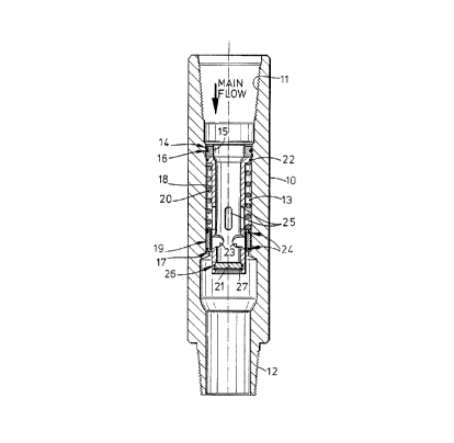
In Fig. 1 of the drawings, the check valve consists of
a body 10 which is adapted for connecting in line
coaxially with a kelly (not shown) and a drillstring (not
shown). Thus, the check valve is inserted at the kelly
joint which is the usual point of connection between the
WO 93/1133f~ ~ ~ ~ ~ ~ ~ ~ I'CT/GB92/0219R
'~~
kelly and the drillstring. The top or input end of the
check valve has a standard tapered screw-threaded box or
socket 11; and the other end of the check valve has a
standard tapered screw-threaded hollow pin 12.
Alternative configurations of screw-threaded connectors
may be chosen according to specific requirements, for
example for use in a top drive system ar in any
arrangement of tubulars to check fluid loss.
An intermediate portion of the valve body 10 defines a
cylindrical bore 13 at the upper end of which there is
provided a screw-threaded portion 14 and an upstream stop
means in the form of an annular retaining collar 15 which
incorporates a fluid-tight seal ls. The lower end of the
bore 13 defines a downstream stop means in the form of a
step 17 which,.in conjunction with the retaining collar 15
locates a fluid flow control means consisting of a tubular
valve member 18, a sleeve seal 19, a compression spring
a
2~, and a frangible closure in the form of a toughened
soda-lime glass disc 21.
More particularly, the upper end of the tubular valve
member 18 is flanged to define an annular piston 22 which
slidably engages the bore 13 and provides an upper land
for the compression spring 20. The lower end or
downstream portion of the tubular valve member 18 is
provided with streamlined openings or ports 23, and the
same vicinity of the tubular valve member 18 is engaged by
the sleeve seal 19 which is also slidably received in the
1~0 93/ 11336 PCT/ G I39210219t~
-4 -
bore 13 and is provided with sliding seals 24. The upper
end face of the sleeve seal 19 provides a land for the
lower end of the compression spring 20. The annular space
between the tubular valve member 18 and the bore 13 is in
communication with the interior of the tubular valve
member 18 by way of four equi-angularly spaced slots 25
which serve to "vent" the said annular space and also
allow for clearance therefrom of particles or other solid
matter which may have settled out from the drilling fluid.
The glass disc 21 is located in a recess at the
downstream end of the tubular valve member 18 together
with a fluid tight seal 26; and the disc 21 is retained.by
a snap ring 27.
The strength or force of the compression spring 20 is
determined with reference to the weight of a column of
drilling mud above the check valve in the kelly or other
tubular whilst the fluid is static. Thus, the spring
a
strength is sufficient to support the weight of the mud
column with the upper end of the tubular valve member 18
in abutment with the retaining collar 15 and the ports 23
within the sleeve seal 19. In this condition, the mud
column within the kelly or other tubular is retained and
the lower joint with the drillstring may be disconnected
without any significant loss of drilling fluid.
In resuming drilling operations and mud pumping, the
tubular valve member 18 is shifted axially downwards
against the compression spring 20 by virtue of pressure
WO 93/1133fi ~ ~ ~ ~~ ~ ~ ~ YCT/C:B92/021t)?~
drop over the tubular valve member 18 during flow of
drilling fluid. Thus, the ports 23 discharge into the
valve body 10 immediately below the sleeve seal 19, the
main flow of drilling fluid being through the tubular
valve member 18 and the ports 23.
Whilst the check valve is closed, and with the
drillstring still connected, any "pressure kicks" within
the drillstring will act on the lower end face of the
sleeve seal 19 which may shift axially upwards against the
compression spring 20 thereby relieving the pressure kick
through the parts 23. It will be understood that the
arrangement described is capable of permitting virtually
full reverse flow in the event of a severe pressure kick. .
In the event that it becomes necessary to deploy
wireline tools downhole, straigl'.t-through access to the
drillstring is gained by first dropping a cone-tipped
sinker on a wireline into the kelly or top drive so that
-. a
the sinker tip penetrates the stressed surface of the
glass disc 21 causing the latter to disintegrate.
Wireline tools may then be deployed; and a new or fresh
glass disc may be fitted subsequently. The choice of a
toughened soda-lime glass is preferred because this
material reliably disintegrates to a fine particulate
condition, thus reducing the risk of larger glass
fragments impeding or interfering with the wireline tools.
In Fig. 2 of the drawings, parts corresponding with
those in Fig. 1 are given the reference numerals used in
...,_..... -;,.~. ,.. ,..~ .,....3......, ...;.. ::... ,:.,. : ,,,....., ,..
.. ". ... ...
..~.. . ,~:.
.y..
'1Y~:
...... .. . . . , ., .. , r..v ..,.. ,.. . , ., . .,.... .x , _.. t.. ........
, n..,.v....\." ..,.'rv, t.. .a. , -... .. .v v.. .v ........ v . . .. ..,.. ,
a . . . ...
WO 93/11336 ~ ~ P(°T~G892~021~~H
'~~.~~~ '
-6 -
Fig. 1.
In Fig. 2, the body 10A of the check valve is
configured as a saver sub which is used in the industry as
the preferred connection between a top drive shaft 28 and
drillstring 29. The downstream pin of a saver sub can be
recut to compensate for wear resulting from repeated
connection/disconnection to and from the drillstring.
When further recutting of the saver sub is impossible,
then the entire saver sub is relatively cheap to replace.
Particularly in a top drive arrangement, there is a
practical limit to the axial dimension of saver sub which
can be accommodated without compromising the vertical
action. of the top drive arrangement. Accordingly, the
check valve described with reference to Fig. 1 above may
not be suitable with some top drive arrangements.
In order to accomplish an axially compact check valve,
the tubular valve member 18 and the sleeve seal 19A of
Fig. 2 are accommodated substantially within the upstream
hollow pin 30 of the saver sub. Moreover, the pin 30 is
provided with an upstream non-threaded extension 31 which
is accommodated within the top drive shaft 28 and provides
additional axial'length whereby the appropriate check
valve action can be accomplished having regard to required
spring rate of the spring 20 and the necessary travel of
the tubular valve member 18.
A conventional standard saver sub has a
straight-through bore. However, the present saver sub has
CVO 93/11336 PC'f/C:I392/0219H
_;
an enlarged middle portion defining a chamber 32 which
accommodates the downstream end portion of the tubular
valve member 18 and discharge from the ports 23 when the
check valve is actioned by operation of the mud pumps.
In the Fig. 2 embodiment, the toughened soda-lime
glass disc 21A carries a relatively small check valve 33
of the ball-check type and which is fitted to the glass
disc 21A through a central opening therein. The check
. valve 33 allows a driller to detect pressures within the
drillstring with the main check valve closed and with the
circulation stopped. It will be understood that the small
check valve 33 is disposable in the event that the
facility for wire-line access is used. .
In the Fig. 2 embodiment, the upstream stop means
consists of a circlip 1~A. Also, the annular space
occupied by the compression spring 20 is vented to the
inside of the tubular valve member 18 through openings
25A. Also, the sleeve seal 19A, as can be seen by
inspection of the drawing of Fig. 2, consists of a moulded
sleeve casing with inserted ring-seals.