Note: Descriptions are shown in the official language in which they were submitted.
l- 2124707
-
TAILORED ERROR PROTE~TION
Field of the Invention
This invention relates to co",.ll~ ic~tion systems for co.--.~-l-l-ic~ting a
plurality of inro~ a~ion signals over a channel and more particularly to error
s protection coding arrangements for use in such co-----.llllic~tion systems.
Back~round of the Invention
A c-,----,-~nic~tions system comprises a tr~n~mitter coupled to a receiver
via a co--..o--~-iç~tic n channel. The system functions to send and receive information
signals. In the course of co--..-----~icating information signals through the channel,
10 such signals may be corrupted by channel noise and other error sources (e.g., fading)
associated with the channel. In a digital co--...-ul-ication system, these error sources
may be responsible for, among other things, altering the content of the information
received. To help prevent such error sources from collup~irlg received information
signals, any of a number of channel coding techniques may be utilized in system
15 tr:~nsmitter and receiver design.
Generally, a channel coding technique helps mitig~te the effects of error
sources by introducing so-called "red-lnd~ncy" to the information to be
co~ ted. Because of this re-llln(l~ncy, the likelihood that noise will corrupt
comm~lnic~t~d information is reduced. Some co,--l-,llnic~tiQn errors may be
20 completely elimin~t~d
Some co.~-l,-...-i~tion systems transmit more than one information
signal over a single channel. This may be accomplished with use of a convention~l
multiplexer combining individual information signals into a combined signal for
tr~n~mi~ion over the channel. To mitig~te the effects of channel error sources on
2s the co-,-.-,lll-ication of the combined information signal, a channel coder is applied to
the combined signal. The coded result may then be provided to, for example, a
conventional interleaver to help reduce the effects of fading.
The use of a single channel coder for a combined information signal can
adequately guard against channel errors, but it can also be wasteful of bandwidth.
30 This is because each of the individual information signals which form the combined
information signal may have its own distinct level of robustness to channel errors.
For example, an audio signal and a separate information signal
representing alph~nllmeric characters may be multiplexed into a combined
inform~tion signal for tr~nsmi~sion over a radio channel. Such an audio signal might
35 be Beethoven's 5th symphony, while the alphanumeric signal might identify or
-2- 212~7~7
advertise (in advance) the tr~n~mis~iQn of music to be played, to wit, "Beethoven's
5th Symphony." Such an advertisement might be displayed to an interested listener.
Channel errors which result from tr~n~mi~iion of such a combined
signal can manifest themselves differently in each received component signal. A
s channel error affecting the audio portion of the combined information signal might
manifest itself as an almost inaudible click, pop, or momentary signal drop-out.Such a channel error may not be very bothersome or even noticeable, for that matter,
to a listener of the audio program. Moreover, the system receiver may be able totake any one of several possible remedial actions to mitigate the effects of such
o errors on the audio signal. In these ways, the audio signal may be thought of as
"robust" to channel errors.
However, the alph~nllmeric signal is not nearly so robust. In fact, when
channel errors affect the alphanumeric information signal, the result can be more
nearly catastrophic. This is because unlike errors in the audio portion of the
lS combined signal, errors in the alph~nllm~ric signal may manifest themselves in a
fashion which cannot be remedied or ignored, to wit, "Bejth60en*s 17h Sym9hehy."Thus, it may be app~pliate to provide channel coding on the combined
signal sufficient to protect the alph~nllm~ric component. However, such degree of
coding would also be applied to the audio component of the signal -- a degree of20 coding unnecessary to protect the audio signal from the effects of channel errors.
This "overcoding" of the audio component is wasteful of channel bandwidth since
signal re l-lnd~ncy provided by channel coding "costs" bandwidth which might be
used for other purposes.
Summary of the Invention
The present invention provides tailored protection against channel errors
in co,-",~ll.-ication systems which transmit combined inform~tion signals associated
with di~~ degrees of error robustness.
According to an illustrative embodiment of the present invention, a first
info~mation signal having a corresponding first level of error robustness is provided
30 to a first channel coder. The first channel coder applies a first channel code to the
first information signal and provides its coded output to a multiplexer. A second
information signal having a corresponding second level of error robustness (the
second level being greater than the first level) is also provided to the multiplexer.
The multiplexer combines its two input signals and outputs the combined signal to a
35 second channel coder. The second channel coder applies a second channel code to
the combined signal.
'--
-3- ~ 7 ~ 7
The level of error protection provided by the second channel coder is
,~ sufficient to mitigate the effects of channel errors on the second information signal;
~ the second channel coder provides only a portion of the level of error protection
required for the first information signal. The first channel coder applies an additional
5 level of error protection to the first information signal. The combined level of error
protection given the first inforrnation signal suits system design goals for robustness
to channel errors. As a result, a tailored amount of error protection is applied to the
component information signals so as to more efficiently make use of available
bandwidth.
An alternative embodiment of the present invention comprises first and
second channel coders which provide first and second levels of error protection to
first and second inforrnation signals, respectively. The output signals of the first and
second channel coders are then multiplexed together into a combined information
signal for communication over the ehannel.
l S A further alternative embodiment includes a multiplexer for combining
first and second information signals and a channel coder which applies distinct
channel codes to the distinct first and second information signal components of the
combined signal.
According to one aspect of the invention there is provided a method
20 for encoding a first signal and a second signal to provide error protection for the
signals, the first signal requiring greater error protection than the second signal, the
first and second signals for use in communication with a receiver, the receiver for
producing decoded first and second signals corresponding to the first and secondsignals, respectively, the method comprising the steps of: a. encoding the first25 signal with a first error protection code; b. combining the encoded first signal with
the second signal; and c. encoding a combination of the encoded first signal and the
second signal with a second error protection code to generate a cornbined error
protected signal for use in transmission to the receiver, wherein the first signal is
coded with both the first and second error protection codes; wherein said first signal
30 is such that the decoded first signal, when irreparably corrupted due to transmission
of said combined error protected signal, will not affect correct processing of the
decoded second signal by the receiver
According to another aspect of the invention there is provided a
method for decoding a signal received by a receiver, the signal received representing
35 a coded first signal and a coded second signal, wherein the coded first signal is based
7 ~ ~
-3a-
on a first signal coded with use of a first and a second error protection code and
wherein the coded second signal is based on a second signal coded with use of the
second error protection code, the first signal requiring greater error protection than
the second signal, the method comprising the steps of: a. decoding the received signal
5 with a first error protection decoder which corresponds to the first error protection
code to generate a signal comprising a decoded second signal and a partially decoded
first signal; b. separating the partially decoded first signal from the decoded
second signal; and c. decoding the partially decoded first signal with a second error
protection decoder which corresponds to the second error protection code to generate
10 a decoded first signal, wherein the coded first signal is decoded with both the first
and second error protection decoders; wherein said first signal is such that thedecoded first signal, when irreparably corrupted due to transmission, will not affect
correct processing of the decoded second signal by the receiver.
Brief Description of the Drawings
l S Figure 1 presents a first illustrative embodiment of a digital audio
broadcast system transmitter of separate audio and data signals.
Figure 2 presents a rectangular block interleaver for use in the
embodiment of Figure 1.
Figure 3 presents a first illustrative embodiment of a digital audio
20 broadcast system receiver of separate audio and data signals.
Figure 4 presents a second illustrative embodiment of a digital audio
broadcast system transmitter of separate audio and data signals.
Figure 5 presents a second illustrative embodiment of a digital audio
broadcast system receiver of separate audio and data signals.
Figure 6 presents a third illustrative embodiment of a digital audio
broadcast system transmitter of separate audio and data signals.
Figure 7 presents a third illustrative embodiment of a digital audio
broadcast system receiver of separate audio and data signals.
-4 -
Detailed Description
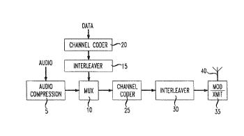
Figure 1 presents a first illustrative embodiment of a digital audio
broadcast system transmitter of separate audio and data signals. The transmitter of
Figure I receives two information signals - audio and alphanumeric data, provides
appropriate channel error protection for each signal, combines the signals into a
single signal for transmission, and transmits a radio signal reflecting the combined
signal. The transmitter of Figure 1 comprises a channel coder 20 coupled to
multiplexer (MUX) 10 via an interleaver 15; an audio compression system 5 also
coupled to the MUX 10; a channel coder 25 coupled to the output of MUX 10; an
interleaver 30 coupled to the output of channel coder 25; and a modulation and radio
transmission system 35 coupled to the output of the interleaver 30 and a transmit
antenna 40.
In accordance ~vith the first illustrative transmitter of Figure 1, the
level of channel error protection required for the audio signal is less than the level of
channel error protection required for the alphanumeric data. This difference in
required levels of error protection is due to the relative nature of the two signals, as
well as a receiver's ability to remediate channel errors in the audio signal. Therefore,
the embodiment of Figure 1 provides different levels of such protection to each such
signal.
An audio signal is provided as input to the audio compression system
5. System 5 may be any system for the compression of either monophonic or stereoaudio signals such as that system described in Canadian Patent Application Ser. Nos.
2,090,159; 2,090,052; 2,090,160 and U.S. PatentNo. 5,227,788 (issued July 13,
1993); System 5 defines conventionaltiming and framing information for use by the
transmitter of Figure 1 and the receiver of Figure 3. Compressed audio information
signals are provided to conventional MUX 10. Alphanumeric data signals also for
transmission are provided to channel coder 20. Channel coder 20 may comprise a
conventional channel coder, such as a conventional Reed-Solomon coder or a binary
block coder such as a BCH coder or a parity check coder. Channel coder 20
provides a first level of error protection for the data signals.
~'
-S- 212g707
A coded data output signal is provided by coder 20 to conventional
interleaver 15. Interleaver 15 scrambles the order of the received coder output
signals to mitigate the effect of burst-like errors in channel decoding. Interleaver 15
can be a rectangular block interleaver m~tche~l to the ch~nn~,l coder 20 and channel
s coder 25.
An illustrative interleaver 15 is presented in Figure 2. As shown in the
Figure, interleaver 15 is 8 bits wide to match an exemplary 8 bit parity check code
applied by coder 20 (7 bits data, 1 bit parity check). Interleaver 15 is N bits in
length, where N is at least as long as the information bit portion of the codeword
lo used in ch:~nnel coder 25. As is conventional in block interleavers, the codeword
output from channel coder 20 is stored across the width of interleaver 15 (8 bits) and
interleaver 15 output is read out along the length of the interleaver 15. The output of
interleaver 15 is also provided to MUX 10. MUX 10 combines the audio and data
signals into a single information signal for transmission.
The single information signal output from MUX 10 is then provided to a
second channel coder 25. Channel coder 25, like channel coder 20, may be a
conventional ch~nnel coder such as a Reed-Solomon coder. In the case of the dataportion of the combined signal, chann~,l coder 25 provides a second layer of channel
coding. This second layer of coding provides adflition~l error protection over and
20 above what is afforded by the channel coding provided by coder 20. In the case of
the audio signal component of the output of MUX 10, ch~nn~,l coder 25 provides the
only layer of channel coding provided by the embodiment for that signal component.
Thus, the ch~nnel coding provided by coder 25 is selected according to the need to
provide error protection for the audio signal. Additional error protection required for
25 the more error-sensitive alpha numeric data signal is provided by coder 20.
The output of coder 25 is provided to conventional interleaver 30.
Tnterleaver 30 could be a rectangular block interleaver matched to channel code 25.
Interleaver 30, like interleaver 15, scrambles the order of coder 25 output signals. In
the case of int~,rl~,aver 30, such scrambling mitigates against the effects of burst-like
30 transmission channel fading.
The output of interleaver 30 is provided to conventional modulation and
radio transmission circuitry 35. Circuitry 35 provides a signal for transmission via
antenna 40 which reflects the output of interleaver 30, as well as additional
conventional timing information used by the receiving radio circuitry.
7 ~! ~ 4 7 ~ :~
-6 -
In accordance with this first illustrative transmitter embodiment,
channel coders 20 and 25 are selected to meet the error protection requirements of
~ the radio system constraints for error protection. Data signals may receive a greater
level of error protection by virtue of two layers of channel coding. Audio signals
5 may receive less error protection by virtue of one layer of channel coding.
Accordingly, channel bandwidth available for expenditure on channel coding/errorprotection of information signals is efficiently used.
Figure 3 presents a first illustrative embodiment of a digital audio
broadcast system receiver of separate audio and data signals. The receiver of Figure
10 3 may be used to receive signals transmitted by the illustrative embodiment of Figure
1. The receiver comprises an antenna 50, conventional radio receiver and
demodulation circuitry 55, a conventional deinterleaver 60 (which complements the
operation of interleaver 30 of Figure 1), a channel decoder 65 (which complements
the operation of channel coder 25 of Figure 1), a demultiplexer (DEMUX) 70 (which
complements the operation of MUX 10 of Figure 1), a conventional deinterleaver 80
(which complements the operation of interleaver 15 of Figure 1), a channel decoder
85 (which complements the operation of channel coder 20 of Figure 1), and an audio
decompression system 75 (which complements the operation of system 5 of Figure
1). DEMUX 70 separates audio and data portions of the combined signal responsiveto conventional timing and framing signals extracted by receiver/demodulator55
from the audio compression system 5 and transmit circuitry 35 in the transmitter of
Figure 1.
The channel decoders 65, 85 may be conventional Reed-Solomon or
binary block code decoders corresponding to the encoders in Figure 1. The channel
decoder 65 provides an output flag when it fails to decode a codeword. This flag is
utilized by an error mitigation/muting mechanism in the audio decompression system
75 and by the second decoder ~5 for erasure correction. Such a flag will form part
of channel decoder 65 output through DEMUX 70 to the audio decompression system
75 and deinterleaver 80 to channel decoder 85. The audio decompression system
may be the complementary decompression system as taught by the prior art.
Figure 4 presents a second illustrative embodiment of a digital audio
broadcast system transmitter of separate audio and data signals. The embodiment of
Figure 4 is similar to that of Figure 1 in its use of an audio compression system 105,
conventional MUX 115, interleaver 125, and modulationlradio transmission circuitry
130. However, the embodiment of Figure 4 differs from that of Figure 1 in its
-.
, .
7 ~3 7
placement and consequent use of channel coding 1 10, 120, and its use of a single
" interleaver.
In accordance with the operation of Figure 4 (and Figure 1), the audio
information signal requires less error protection than does the alphanumeric data
5 signal. The embodiment of Figure 4 therefore provides separate conventional
channel coders which provide to the individual signals the requisite amount of error
protection. Because the data signal is more sensitive to errors than the audio signal,
channel coder 120 provides a relatively powerful channel code to the data signal.
Channel coder 110 provides a comparatively less powerful code to the audio signal.
As with the first embodiment, the channel coders 1 10, 120 of the
second illustrative transmitter embodiment are selected to meet the error protection
requirements of the radio system. In this case, data signals receive a greater level of
error protection by virtue a more powerful channel code than that applied to theaudio signal. Such a more powerful code is not "wasted" (i.e., does not over-code)
on the audio signal. Accordingly, channel bandwidth available for expenditure onchannel coding/error protection of information signals is eff1ciently used. Timing
and framing information is defined by system 105 and circuitry 130 for use by the
transmitter of Figure 4 and the receiver of Figure 5.
The embodiment of Figure 4 does not include a separate interleaver
for the data signal prior to the MUX 115. This is because the only expected
burst-like errors occurring prior to decoding are due to channel fading. Such errors
may be mitigated by the use of interleaver 125 (and a complementary deinterleaver
155 in the receiver). Thus, no additional interleaving is necessary. The embodiment
of Figure 4 is expected to have lower transmission delay for the data than that in
Figure 1. This is due to the fact that the embodiment of Figure I uses an extra
interleaver.
Figure 5 presents a second illustrative embodiment of a digital audio
broadcast system receiver of separate audio and data signals. This embodiment iscomplementary to that of Figure 4. The receiver of Figure 4 comprises an antenna145, conventionalradio receiver and demodulationcircuitry 150, a conventional
deinterleaver 1S5 (which complementsthe operation of interleaver 125 of Figure 4),
and a DEMUX 160 (which complements the operation of MUX 1 15 of Figure 4).
The embodiment further comprises a channel decoder 165 (which complements the
operation of channel coder 120 of Figure 4), a channel decoder 170 (which
complements the operation of channel coder 1 10 of Figure 4), and an audio
7. ~ ~ ~ 7 ~ ~
-8 -
decompression system 175 (which complements the operation of system 105 of
Figure 4). Timing and framing information needed by the receiver is extracted by~ circuitry 150 as is conventional. As discussed above, the channel decoders 165, 170
may be conventional Reed-Solomon or binary block decoders corresponding to the
5 encoders in Figure 4.
Figure 6 presents a third illustrative embodiment of a digital audio
broadcast system transmitter of separate audio and data signals. The embodiment
comprises an audio compression system 200, a MUX 205 for combining data and
coded audio signals into a single signal for tr~nsmi~ion, a channel coder 210 for
10 applying one of two available channel codes to the combined signal, a conventional
interleaver 215, conventional modulation and radio transmission circuitry 220 and an
antenna 225. System 200 provides timing and framing information for the use by the
transmitter of Figure 6 and the receiver of Figure 7. Circuitry 220 provides
additional timing information as is conventional.
The salient aspect of the third embodiment of Figure 6 relative to the
those of Figures 1 and 4 discussed above is the third embodiment's use of a single
channel coder 210. Coder 210 applies one of two channel codes to the combined
signal output from MUX 205 depending on whether coder 210 is to code the audio
or data signal portion of the combined signal. These channel codes may be distinct,
20 conventional Reed-Solomon or binary block channel codes. MUX 205 provides
coder 210 with a control signal specifying the channel code to be used. The MUX
205 provides combined signal values in block sizes corresponding to the requirements
of the particular coding techniques being implemented by coder 210.
MUX 205 provides blocks of information of length suitable for
25 channel coder 210 to generate a complete codeword. These blocks will include either
audio signals or data signals. Channel coder 210 advantageouslyprovides codewords
matched to interleaver 215 by providing the same matched codeword length for both
audio and data signals.
As with the embodiments discussed above, the requirements for error
30 protecting audio signals and alphanumeric data signals differ. Consequently, coder
210 implements a relatively powerful coding technique for data signal portions of the
combined signal and a less powerful coding technique for audio signals.
Figure 7 presents a third illustrative embodiment of a digital audio
broadcast system receiver of separate audio and data signals. The receiver of Figure
35 7 comprises an antenna 235, conventional radio receiver and demodulation circuitry
- 9 - :
240, and a conventional deinterleaver 245 (which complements the operation of
interleaver 215 of Figure 6). The embodiment further comprises a channel decoder~ 250 (which complements the operation of channel coder 210 of Figure 6), a DEMUX
255 (which complements the operation of MUX 205 of Figure 6)~ and an audio
decompression system 260 (which complements the operation of system 200 of
Figure 6). The channel decoder 250 applies, e.g., one of two conventional
Reed-Solomon decoding techniques corresponding to the encoding provided in Figure
6 in accordance with timing information extracted by circuitry 240.
The embodiments discussed above have focused on two signals which
are coded and combined. These two signals require different levels of error
protection. While a two signal embodiment illustrates clearly the principles of the
present invention, other embodiments may be provided which include a combinationof more than two signals. In such embodiments, two or more signals require
different levels of error protection.
Also, while the signals for coding are illustratively presented as
conventional audio and alphanumeric data symbols, the signals are not constrained to
these forms or categories. For example, the "audio" signal for coding may itself be a
combination of an audio signal and a data signal.
The embodiments discussed above have focused on block codes.
Other embodiments may be provided which use convolutional codes. In addition,
while the embodiments discussed above use rectangular block interleavers, other
embodiments may be provided which use other types of interleavers such as, for
example, convolutional interleavers.
'
.. ~. ~