Note: Descriptions are shown in the official language in which they were submitted.
2124878
The present invention relates in general to radios
and, in particular, to a transmitting and receiving
system and radio transmitter/receiver apparatus to
be utilized within the system, wherein the radio
apparatus is capable of transmitting and receiving a
transmission signal on two or more radio frequen-
cies, such as found in a system implementing a
continuous frequency hopping protocol.
Radio transmitters and receivers, taking the form
of cordless telephones, cellular phones, citizen
band radios and the like, are well known in the art.
In general, these radios particularly those that
receive on multiple channels, utilize a superhetero-
dyne receiver. Superheterodyne (also.known as
superhet) receivers receive a signal and mix the
received signal with a local oscillator signal to,
in turn, convert the received signal to a lower
intermediate frequency (usually on the order of 10
I~iz). Changing the local oscillator frequency tunes
the receiver to permit reception of signals on
various channels.
The use of a mixer to obtain the intermediate
frequency introduces certain problems. The mixer
accepts two signals, A and B, the received signal
and the local oscillator frequency respectively, and
outputs the following signals: A + B, A - B and B -
A. The intermediate frequency signal results from
the A - B or B - A output. The signal located at A
+ B will be hopelessly out of range for nominally
used frequencies and is typically ignored. Even so,
it can be seen that there exist two frequencies for
signal A, which result in the same intermediate
frequency. One value for signal A, of course, is
the desired RF signal. The other is referred to as
an image response. It can be seen, from the above
93525f 2
equations that the image response°s frequency is
located twice the intermediate frequency from the
desired RF signal's frequency.
There have been a number of approaches to removing
or rejecting the image response which accompanies
the desired RF signal. One such approach involved
the use of tuned RF amplifiers. However, these
tuned amplifiers are expensive and difficult to
tune. Another approach involves the use of image-
reject filters (or mixers). Image-reject filters
are also expensive and frequently difficult to
design.
Another approach to image rejection involves a
method called "direct conversion", wherein the
intermediate frequency is set to zero, i.e. the
local oscillator frequency is equal to the received
transmission frequency. While this approach elimi-
nates the image problem, the processing of the
resulting intermediate frequency signal is complex
-- requiring expensive active filters, which may
have inferior noise characteristics. Furthermore,
there may be local oscillator frequency reradiation
in the channel.
It is, thus, an object of the present invention to
provide an inexpensive approach to eliminating image
signal concerns in a superhet receiver.
It is a further object of the present invention to
provide a compact band-plan for a multiple channel
transmitting and receiving system wherein image
responses associated with the desired RF signal are
positioned such that the desired RF signal is trans-
mitted and received without interference from sig-
nals on the image response frequencies.
These and other objects will become apparent in
light of the specification, drawings and claims.
93525f 3
~~2~R~8
A preferred embodiment of the invention comprises
a transmitting and receiving system having two or
more radios, each capable of transmitting and re-
ceiving a transmission signal on two or more radio
frequencies wherein a first radio transmits on a
selected frequency at a predetermined time interval
and a second radio recovers the transmitted signal.
Each of the two or more radio frequencies are sepa-
rated by at least one channel spacing. Channel
spacing being the minimum set frequency separation
between two channels or frequencies.
The first radio includes first radio frequency
generating means for generating a first selected one
of the two or more radio frequencies. In a pre-
ferred embodiment, first radio frequency generating
means includes a modulator filter, modulator and
frequency synthesizer means which, in combination,
form a modulated transmission signal.
The first radio further includes first transmis-
sion means for transmitting the transmission signal
on the first selected one of the two or more radio
frequencies. In a preferred embodiment, transmis-
sion means includes a power amplifying means which
amplifies the modulated transmission signal and an
antenna means which radiates the modulated transmis-
sion signal. This embodiment implements a time
division duplexing system wherein the first and
second radios transmit at one time and receive at
another contiguous time interval. In this embodi-
ment, the first transmission means further includes
isolation means, which may include an RF switch, for
isolating the transmission signal from the receiver
section while the transmission signal is amplified
out onto the antenna means.
The second radio which recovers the transmission
93525f
~~24878
signal on the selected one of the two or more radio
frequencies, includes first receiver means for
receiving the transmission signal on the selected
one of the two or more radio frequencies as trans-
mitted by the first radio's first transmission
means.
In a preferred embodiment, the first receiver
means includes antenna means, isolation means and
receiver amplifying means. The antenna means re-
ceives the transmission signal on the selected
frequency. In this embodiment, the receiver means
also includes isolation means operably connected to
the antenna means for isolating the transmission
signal from the transmission section of the second
radio. The receiver amplifying means operably
accepts the transmission signal from the antenna
means via the isolation means for producing an
amplified radio signal, which is the output of the
first receiver means.
The second radio further includes a first interme-
diate frequency generating means which accepts the
output from first receiver means for generating an
intermediate frequency signal which is substantially
equal to an integer multiple of the channel spacing.
In a preferred embodiment, first intermediate
frequency generating means includes a frequency
synthesizer means containing a voltage controlled
oscillator for generating a desired one of the two
or more radio frequencies. The frequency synthesiz-
er means is controlled by control means which indi-
cate to the frequency synthesizer means the desired
one of the two or more local oscillator frequencies
to be generated. The control means includes means
for storing frequency values representing selected
ones of the two or more frequencies. These selected
93525f 5
°~1~~~"~8
frequencies are located at a selected integer multi-
ple of the predetermined channel spacing from the
other selected frequencies. Selecting means selects
one of the frequency values representing the desired
one of the two or more frequencies from the storing
means.
First intermediate frequency generator means
finally includes a mixer which mixes the desired one
of the two or more frequencies output by the fre-
quency synthesizer means and the transmission signal
from the first receiver means producing the interme-
diate frequency signal. By forcing the intermediate
frequency signal to be substantially equal to an
integer multiple of the channel spacing, the image
response corresponding to the selected one of the
two or more radio frequencies is separated by twice
the intermediate frequency from the first selected
one of the two or more radio frequencies. Thus,
channels for the two or more transmission frequen-
cies can be selected so as not to be located on the
image responses corresponding to any of the two or
more transmission frequencies.
In a preferred embodiment, the integer multiple is
equal to one, such that the intermediate frequency
is substantially equal to the predetermined channel
spacing and the frequency range is most efficiently
and completely utilized.
In a preferred embodiment, the first and second
radios further receive and transmit, respectively.
The second radio transmits its transmission signal
on a second selected one of the two or mare radio
frequencies at another of the predetermined time
intervals which is received by the first radio. So
as to provide for transmission, the second radio
further includes second radio frequency generating
93525f
X124878
means and second transmission means. So as to pro-
vide for reception, the first radio further includes
second receiver means and intermediate frequency
generating means.
In this preferred embodiment, the first selected
one of the two or more radio frequencies differs
from the second selected one of the two or more
radio frequencies by the predetermined channel
spacing. This frequency arrangement can be further
utilized such that when each radio switches from
receiving to transmitting mode frequency switching
is not required. For instance, in the second radio,
the second selected one of the two or more radio
frequencies is utilized by the first intermediate
frequency generator and by the second radio trans-
mission means whereby time division duplexing is
simplified.
The operation of this system essentially involves
transmitting a signal on one of multiple selected
transmission frequencies, which is received by
another radio transmitter/receiver. The receiving
radio contains a local oscillator, transmitter
amplifier, isolation switch, antenna, receiver
amplifier and mixer. The local oscillator is oper-
ated offset an integer number of channels from the
one transmission frequency upon which the received
signal was transmitted. The output of this local
oscillator and the received signal output by the
first receiver means are connected to the mixer,
which, in turn, outputs an intermediate frequency
signal. The frequency values stored in the control
means have been selected as transmission frequencies
to be those frequencies upon which no image response
is located, thus, obviating the need for image
rejection.
93525f
~~~~s7~
Fig. 1 of the drawings is a schematic block dia-
gram of a prior art transmitter and superheterodyne
receiver;
Fig. 2 of the drawings is a schematic block dia-
gram of the invention showing, in particular, the
absence of an image rejection filter;
Fig. 3 of the drawings is a schematic block dia-
gram of the local oscillator frequency generator
means showing, in particular, a frequency synthesiz-
er, a voltage controlled oscillator and a control
means;
Fig. 4 of the drawings is a radio frequency band
plan diagram for a first radio showing, in particu-
lar, a preferred approach to locating the two or
more transmission frequencies and the two or more
image response frequencies corresponding thereto;
and
Fig. 5 of the drawings is a radio frequency band
plan diagram for a second radio showing, in particu-
lar, a preferred approach to locating the two or
more transmission frequencies and the two or more
image response frequencies corresponding thereto.
While this invention is susceptible of embodiment
in many different forms, there is shown in the
drawings and will herein be described in detail, one
specific embodiment and system, with the understand-
ing that the present disclosure is to be considered
as an exemplification of the principles of the
invention and is not intended to limit the invention
to the embodiment and system illustrated.
Fig. 1 of the drawings is a schematic block dia-
gram of a prior art superheterodyne receiver/trans-
mitter 10. As discussed above, superheterodyne
receivers utilize a set intermediate frequency
93525f 8
212.~~'~8
signal to recover a received transmission signal.
The generation of this set intermediate frequency
signal is accomplished by mixer 12, which receives
local oscillator frequency 13 from oscillator 14 and
a received signal 15 from an amplifier 17. Superhet
receiver 10 includes image rejection filter 11 to
reject any image response. Mixer 12 will thus
produce set intermediate frequency signal 16, which
contains only the desired RF signal.
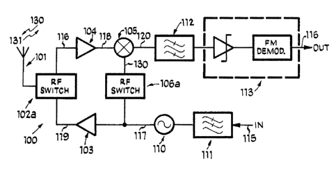
Fig. 2 of the drawings is a schematic block dia-
gram of radio transmitter/receiver apparatus 100.
Apparatus 100 is the type of apparatus which is
capable of transmitting and receiving on two or more
channels. Some apparatuses of this type, including
a preferred embodiment of radio transmitter/receiver
apparatus 100, utilize distinct predetermined trans-
mission and reception time intervals to time divi-
sion duplex transmission and reception.
Apparatus 100, as shown in Fig. 2, is comprised of
both receiver and transmitter sections. It is
contemplated, that the receiver and transmitter
could be two separate apparatuses; however, the
additional costs associated with this separation due
to various redundancies, such as two antennas and
two oscillator means that would be required, may
dictate against such separation.
In a preferred embodiment, transmitter/receiver
apparatus 100 comprises antenna means 101, isolation
means 102, power amplifying means 103, local oscil-
lator generator means 110, modulation filter means
111, receiver amplifying means 104, mixer 105,
intermediate filter means 112, cross-over prevention
means 106 and signal detector 113.
Antenna means 101 radiates transmitted radio
signal 130 during predetermined transmission time
93525f 9
21248?8
intervals and receives the received radio signal 131
during predetermined reception time intervals.
Antenna means 101 may be of the conventional type
utilized in cordless telephones, cellular telephones
or other types of radios. Antenna means 101 is
operably connected to isolation means 102, which may
be an RF switch 102. Isolation means 102 isolates
the receiver section of apparatus 100 from the
transmitter section, as is standard in the art. Of
course, where apparatus 100 would be implemented as
a separate receiver and transmitter, each would
require separate antenna means 101, and, isolation
means 102 could be omitted.
The transmitter section of apparatus 100 accepts
modulating signal i15 containing the information to
be transmitted, which may consist of voice and/or
data signals. This modulating signal 115 may be
generated by a microphone or even a digital circuit,
in the case of digital communications. Modulating
signal 115 is fed into modulator filter means 111
which shapes the modulation of modulating signal 115
to fit the transmission channel. The output of
modulation filter means 111 is fed into a modulator
(not shown) which interacts with local oscillator
generator means 110 to produce transmission signal
117.
Local oscillator generator means 110, as shown in
Fig. 3, includes frequency synthesizer means 121.
Frequency synthesizer means 121, which includes
voltage controlled oscillator 120, generates the
local oscillator frequency. This local oscillator
frequency is selected by control means 122, which is
operably connected to frequency synthesizer means
121. Control means 122 includes means for storing
frequency values representing selected ones of the
93525f 10
2124878
two or more frequencies. The selected frequencies
are located a selected integer multiple of the
predetermined channel spacing from each other.
These values are selected from the storing means by
selecting means, which is operably connected to the
storing means.
The transmitting section of radio
transmitter/receiver apparatus 100 further includes
power amplifying means 103 for accepting and ampli-
fying modulated transmission signal 117 generated by
the modulator and local oscillator generator means
110 toward outputting amplified radio signal 119.
Power amplifying means 103 is operably connected to
isolation means 102 toward transmitting amplified
radio signal 119 via antenna means 101 as transmit-
ted radio signal 130.
The receiver section of radio transmitter/receiver
apparatus 100 includes receiver amplifying means
104, mixer 105 and selective matching means. Anten-
na means 101 receives received radio signal 131 from
another radio apparatus (not shown) transmitted at a
selected one of the transmission frequencies.
Received radio signal 131 is operably accepted by
local oscillator generator receiver amplifying means
104 via isolation means 102 toward producing an
amplified radio signal 118.
The receiver section further includes first in-
termediate frequency generating means, which in a
preferred embodiment comprises local oscillator
generator means 110 and mixer 105. Local oscillator
generator means 110 is also utilized by the trans-
mission section of apparatus 100, but given the time
division duplex nature of apparatus 100 there is no
inherent problem. In fact, as will be described
later there is an inherent benefit from sharing
93525f 11
212878
local oscillator generator means 110 -- beyond the
cost benefits.
First intermediate frequency generating means
generates intermediate frequency signal 120, which
has a frequency substantially equal to an integer
multiple of the channel spacing, whereby an image
response corresponding to the transmission frequency
is separated by twice the intermediate frequency
from the transmission frequency. Because the loca-
tions of the image responses are "in-band" at known
locations, the two or more radio transmission fre-
quencies can be selected so as not to be located on
the image responses corresponding to any and all of
the two or more radio transmission frequencies.
These values are stored in control means 122 and are
utilized as described above.
Mixer 105 accepts amplified radio signal 118 and
local oscillator generator means output 130 and
produces intermediate frequency signal 120. In-
termediate frequency signal 120 has a frequency
substantially equal to the difference between the
frequency of the received transmission signal 131
and local oscillator generator means output 130.
Local oscillator generator means output 130 is the
second selected one of the two or more radio fre-
quencies which corresponds to received radio signal
131 which has a first selected one of the two or
more radio frequencies, such that the frequency of
intermediate frequency signal 120 is substantially
equal to an integer multiple of the predetermined
channel spacing.
The receiver section finally includes intermediate
filter means 112 connected to the output of mixer
105 for passing intermediate frequency signal 120 to
signal detector 113, which includes a limiting
93525f 12
?12~8~8
amplifier and FM detector.
One embodiment of the invention may include cross-
over prevention means 106 operably connected between
local oscillator generator means 110 and mixer 105
far preventing the introduction of transmission
signal 117 into the receiver section. Cross-over
prevention means 106 comprises RF switch 106.
During predetermined transmission time intervals, RF
switch 106 is open so as to prevent modulated trans-
mission signal 117 from entering mixer 105. During
predetermined reception time intervals, RF switch
106 is closed so as to allow local oscillator gener-
ator means 110 to operate in conjunction with mixer
105 so as to provide first intermediate frequency
signal generating means. In a preferred embodiment,
during predetermined reception time intervals there
is no modulating signal 115 such that transmission
signal 117 solely consists of the frequency generat-
ed by local oscillator generator means 110.
In operation, two or more radio transmitter/re-
ceiver apparatuses 100 may be deployed and in commu-
nication within one another. One such exemplary
system is that of a frequency hopping cordless
telephone system. In this system, the selection
means of control means 122, relying on timing, at
predetermined time intervals selects a first select-
ed one of the frequencies. The selected frequency
is dependent upon a predetermined pseudo-random
code, known by all the radios in the system.
A second radio recovers the transmission signal on
the first selected frequency by selecting a second
selected one of the two or more radio frequencies
which corresponds to the first selected one of the
two or more radio frequencies such that the interme-
diate frequency signal generated by the first in-
93525f 13
?12~R7~
termediate frequency signal generating means is an
integer multiple of the channel spacing. It is
assumed that the first and second radios are syn-
chronized such that this selective correspondence
can be accomplished based upon a pseudo-random code
known to both of the.radios. Where the integer
multiple equals one, i.e. the channel spacing equal
the intermediate frequency, a radio frequency band-
plan like the one shown in Figs. 4 and 5 is uti-
lized.
Fig. 4 is a radio frequency band plan diagram far
the first radio and Fig. 5 shows the plan for the
second radio with the corresponding frequencies
generated by the receiving radio, second and first
radios, respectively, overlaid thereon.
Transmission channels 150-156 are each utilized at
predetermined transmission time intervals to trans-
mit a signal from the first radio to the second
radio. The second radio receives the transmitted
signal and generates an intermediate frequency
signal utilizing the corresponding one of the two or
more radio frequencies 160-166, wherein selected
radio frequency 160 corresponds to transmission
channel 150 and is generated at the second radio's
predetermined reception time interval -- the same
time as first radio's predetermined transmission
time interval.
As can be seen from Fig. 4, each selected radio
frequency is one channel spacing away from its
corresponding channel. Thus, resulting in an in-
termediate frequency substantially equal to the
channel spacing whereby image response 171, which
corresponds to the selected radio frequency, is
twice the intermediate frequency away from the
transmission channel frequency. Thus, locations for
93525f 14
22248"8
the two or more transmission frequencies can be
selected so as not to be located on the image re-
sponses corresponding to any and all of the trans-
mission frequencies. So due to transmission fre-
quencies 150 - 156 image responses 170 - 173 will
exist in known "in-band" locations such that trans-
mission frequencies 150 - 156 can be selected so as
not to be located on any of image responses 170
-173.
The frequency band plan for the second radio, as
shown in Fig. 5, is a mirror image of the band plan
for the first radio, shown in Fig. 4. This reflec-
tion simplifies the time division duplexing utilized
in the transmission and reception system. For
example, in the first time interval, the first radio
may transmit on channel three 152. Assuming the
second radio is in sync with the first it will be
generating selected radio frequency three 162, such
the resulting intermediate frequency signal will
have a frequency equal to the channel spacing.
In the second time interval, the second radio
transmits on channel three 182 and first radio will
generate selected radio frequency three 192. Figs.
4 and 5 have the same scale and their axes are
aligned, such that, it can be seen that first radio
in "moving" from transmitting on channel three 152
to receiving utilizing selected radio frequency
three 192, the frequency generated by local oscilla-
tor generator means 110 does not change. Thus,
switching between transmission and reception occurs
with no delay with the same no-delay-switch occur-
ring in the second radio because of the transmis-
sion-selected radio frequency pairing.
As can be further be seen in Fig. 4 (and 5), the
image responses corresponding to transmission fre-
93525f 15
21248~~
quencies 150 - 156 are overlapped into four response
locations. This overlap results from the interrela-
tion of the transmission-selected radio frequency
pairs themselves and to each other and because the
chosen integer multiple is one. In a system utiliz-
ing the integer multiple of two or three, the band
plan will not be compact and the image responses
will not overlap as readily.
It is contemplated that this transmission and
reception system be utilized within a frequency
hopping system, wherein hopping would occur between
pairs after a single time division duplexing switch
occurs (i.e. both the first and second radios trans-
mit once before the sequence continues onto another
pair).
The foregoing description and drawings merely
explain and illustrate the invention and the inven-
tion is not limited thereto except insofar as the
appended claims are so limited and as those skilled
in the art who have the disclosure before them will
be able to make modifications and variations therein
without departing from the scope of the invention.
93525f 16