Language selection

Search

Patent 2124889 Summary

Third-party information liability

Some of the information on this Web page has been provided by external sources. The Government of Canada is not responsible for the accuracy, reliability or currency of the information supplied by external sources. Users wishing to rely upon this information should consult directly with the source of the information. Content provided by external sources is not subject to official languages, privacy and accessibility requirements.

Claims and Abstract availability

Any discrepancies in the text and image of the Claims and Abstract are due to differing posting times. Text of the Claims and Abstract are posted:

  • At the time the application is open to public inspection;
  • At the time of issue of the patent (grant).
(12) Patent: (11) CA 2124889
(54) English Title: METHOD OF SECURING A FILTER ELEMENT TO A BLADE OF A FAN
(54) French Title: METHODE POUR FIXER UN ELEMENT FILTRANT SUR UNE PALE DE VENTILATEUR
Status: Term Expired - Post Grant Beyond Limit
Bibliographic Data
(51) International Patent Classification (IPC):
  • F04D 29/70 (2006.01)
  • B01D 35/02 (2006.01)
  • F04D 29/26 (2006.01)
  • F04D 29/38 (2006.01)
  • F24F 13/00 (2006.01)
  • F24F 13/28 (2006.01)
(72) Inventors :
  • KURYLIW, WILLIAM (Canada)
(73) Owners :
  • WILLIAM KURYLIW
(71) Applicants :
(74) Agent: NATHAN V. WOODRUFFWOODRUFF, NATHAN V.
(74) Associate agent:
(45) Issued: 1998-07-28
(22) Filed Date: 1994-06-01
(41) Open to Public Inspection: 1994-12-16
Examination requested: 1994-10-11
Availability of licence: N/A
Dedicated to the Public: N/A
(25) Language of filing: English

Patent Cooperation Treaty (PCT): No

(30) Application Priority Data:
Application No. Country/Territory Date
08/076,748 (United States of America) 1993-06-15

Abstracts

English Abstract


There is described a method of securing a filter element
to a blade of a fan. Firstly, form a cavity within a fan
blade. The cavity has a tip end oriented toward a tip of the
fan blade and a root end oriented toward a root of the fan
blade. Secondly, form at least one flow passage extending from
one broad surface of a fan blade through the cavity to an
opposed broad surface of the fan blade, such that air
circulates through the cavity via the flow passages upon
movement of the fan blade. Thirdly, form an access opening
through which a filter element is inserted into the cavity.


French Abstract

Méthode pour fixer un élément filtrant à une pale de ventilateur. La méthode comporte les étapes suivantes : pratiquer une cavité à l'intérieur de la pale, l'extrémité de la cavité étant orientée vers l'extrémité de la pale et une base orientée vers la base de la pale; réaliser au moins un passage d'écoulement partant d'une surface large de la pale en passant par la cavité pour se rendre jusqu'à la face large opposée de la pale de manière que l'air circule dans la cavité par les passages d'écoulement lorsque la pale bouge; réaliser un orifice d'accès par lequel un élément filtrant est inséré dans la cavité.

Claims

Note: Claims are shown in the official language in which they were submitted.

THE EMBODIMENTS OF THE INVENTION IN WHICH AN EXCLUSIVE PROPERTY
OR PRIVILEGE IS CLAIMED ARE DEFINED AS FOLLOWS:
1. A method of securing a filter element to a blade of a fan,
comprising the steps of:
a. firstly, forming a cavity within a fan blade, the
cavity having a tip end oriented toward a tip of the fan blade
and a root end oriented toward a root of the fan blade;
b. secondly, forming at least one flow passage extending
from one broad surface of a fan blade through the cavity to an
opposed broad surface of the fan blade, such that air
circulates through the cavity via the at least one flow passage
upon movement of the fan blade; and
c. thirdly, forming an access opening through which a
filter element is inserted into the cavity.
d. fourthly, inserting a filter element through the
access opening into the cavity.
2. The method as defined in Claim 1, means being provided to
prevent the filter element from being propelled back through
the access opening by centrifugal force.
3. The method as defined in Claim 1, the access opening being
a channel extending at an angle through one of the broad
surfaces of the fan blade adjacent one of the tip end and the
root end.
4. The method as defined in Claim 3, the channel being at an
angle of between 5 degrees and 35 degrees.
5. The method as defined in Claim 3, the channel being
adjacent to and spaced inwardly from the tip end while being
angled toward the root end, such that upon rotation of the fan
blade the filter element is propelled by centrifugal force past
the channel until the filter element engages the tip end
thereby maintaining the filter element within the cavity.

6. A method of securing a filter element to a blade of a fan,
comprising the steps of:
a. forming a cavity within a fan blade, the cavity having
a tip end oriented toward a tip of the fan blade and a root end
oriented toward a root of the fan blade;
b. forming flow passages extending from one broad surface
of a fan blade through the cavity to an opposed broad surface
of the fan blade, such that air circulates through the cavity
via the flow passages upon movement of the fan blade; and
c. forming an access channel communicating with the
cavity through one of the broad surfaces of the fan blade
adjacent to and spaced inwardly from the tip end while being
angled between 5 and 35 degrees toward the root end; and
d. inserting a filter element through the access channel
into the cavity, such that upon rotation of the fan blade the
filter element is propelled by centrifugal force past the
access channel until the filter element engages the tip end
thereby maintaining the filter element within the cavity.

Description

Note: Descriptions are shown in the official language in which they were submitted.


212~889
. .
The present invention relates to a method of securing a
filter element to a blade of a fan.
BA~K~'"'~UND OF THE INVE.NTION
Fans are employed in many homes to serve the function of
moving stagnant air. The concept of securing a filter element
to a blade of the fan in order to filter air thereby trapping
air borne particles as the fan blade moves is taught in a
number of references.
United States Patent 4,753,573 which issued to McKnight
in 1988 discloses a longitl~inAlly exten~;ng channel member
that i8 fixed by adhesive to a fan blade such that a filter
element is supported in an upstAn~;ng position exten~;ng
outwardly from the fan blade.
United States Patent 4,840,650 which issued to Matherne
in 1989 discloses a filter housing having clip8 which attach
the filter housing to a 1~A~; ng edge of a fan blade.
.::
United States Patent 4,889,543 which issued to Burt in
1989 discloses a method and apparatus in which filter elements
extend between adjacent circumferentially spaced apart fan
blades.
It is readily apparent to an observer when a fan is
equ;ppe~ with one of the described devices. Some types of
fans, for example c~;l;ng fans, serve a collateral decorative
purpose. Great care is taken to make ceiling fans
aesthetically R~peAl ;n~ to the consumer. Anything which
potentially detracts from the aesthetic appearance of the fan
is viewed as being undesirable.
;-t~ '' '''': ~i. ; ;'i'' -' '.";t~ ' '' " "~ "'
r '. ~s ,~
4 ~r. ~ ':.;?~, .",i

~'~ 212~889
SUMMARY OF THE INVENTION
What is required is a method of securing a filter element
to a blade of a fan that is relatively unobtrusive.
According to one aspect of the pre~ent invention there i8
provided a method of securing a filter element to a blade of
a fan which includes the following described steps. Firstly,
form a cavity within a fan blade. The cavity has a tip end
oriented toward a tip of the fan blade and a root end oriented
toward a root of the fan bladel Secondly, form at least one
flow passage ext~n~;ng from one broad surface of a fan hlade
through the cavity to an opposed broad surface of the fan
blade, such that air circulates through the cavity via the flow
passages upon mo~ -nt of the fan blade. Thirdly, form an
access opening through which a filter element is inserted into
the cavity.
.
With the method, as described, the filter element is
h~den within the fan blade. The flow passages can be
attractively arranged to be aesthetically pleasing and in no
way detract from the fan's role as a decorative piece.
Although beneficial results may be obtA;ne~ through the method,
as described, ~epen~;ng upon the positioning of the access
open;ng there may be a ten~sncy for the filter element to be
urged back through the access op~n;ng by centrifugal force.
Even more henef;cial results may, therefore, be obtA;ne~ by
providing means to prevent the filter element from being
propelled back through the access opening by centrifugal force.
In order to address this problem, it is preferred that the
access opening be a chAnn~l exte~;ng at an angle through one
of the broad surfaces of the fan blade adjacent one of the tip
end and the root end. The greater the angle of the access
chAnn~l the less likely centrifugal force will be able to
dislodge the filter element. It is preferred that the access
chAnnel being at an angle of between 5 degrees and 35 degrees.

~ 21~89
~....
Although beneficial results may be obtained through the
use of the method, as described, the Applicant has devised a
simple and cost effective manner to maintain the filter element
in position that can withstand and even benefit from
centrifugal force. Even more beneficial results may be
obtained by placing the access chAnnel adjacent to and spaced
inwardly from the tip end while being angled toward the root
end. Upon rotation of the fan blade the filter element is
propelled by centrifugal force past the access chAnnel until
the filter element engages the tip end thereby maintaining the
filter element within the cavity.
According to another aspect of the invention there is
provided a blade for a fan which includes a blade body having
a tip, a root and opposed broad surfaces. A cavity is provided
within the body. The cavity has a tip end oriented toward the
tip of the body and a root end oriented toward the root of the
body. At least one flow passage extends from one broad surface
of the body through the cavity to the opposed broad surface of
the body, such that air circulates through the cavity via the
flow passages upon mov L of the body. An access ~hAnnel to
the cavity extends through one of the broad surfaces of the
body adjacent to and spaced inwardly from the tip end while
being angled toward the root end. Upon rotation of the body
the filter element is propelled by centrifugal force past the
access chAnn~l until the filter element engages the tip end
thereby maintA; n; ng the filter element within the cavity.
BRIEF ~ ~TPTION OF THE DRAWING8
These and other features of the invention will become more
apparent from the following description in which reference is
made to the Appen~e~ drawings, wherein:
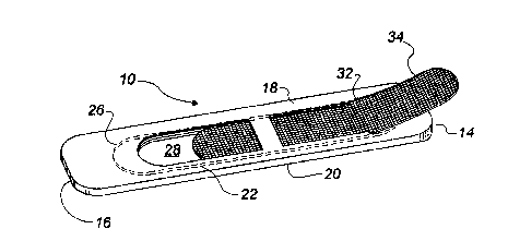
FIGURE 1 is a perspective view of a fan blade constructed
in accordance with the teAch;ngs of the present invention.
~ ,, ~, !,' ." ~~,. ; .~?- '

2 ~ 2 ~ ~ 8 9
FIGU~E 2 is a perspective view of the fan blade
illustrated in FIGURF 1 with a filter element in the process
of being inserted.
FIGUREi 3 is a perspective view of the fan blade
illustrated in FIGURE 1 with the filter element inserted.
FIGURE 4 is a perspective view of the fan blade illustrated in
FIGUREi 1 with the filter element in an operative position.
DE~TT-Fn DESCRIPTION OF THE ~n~r~nA~ EMBODIMENT
The method of securing a filter element to a blade of a
fan, includes the following step~. Firstly, form a cavity
within a fan blade. The cavity having a tip end oriented
toward a tip of the fan blade and a root end oriented toward
a root of the fan blade. Secondly, form at least one flow
passage extending from one broad surface of a fan blade through
the cavity to an opposed broad surface of the fan blade, such
that air circulates through the cavity via the at least one
flow passage upon -v~ of the fan blade. Thirdly, fo_ ;ng
an access openi ng through which a filter element is inserted
into the cavity. In order to successfully follow the
teAch~ngs of the described method, some means must be employed
to pL~Vent centrifugal force exerted upon rotation of the fan
blade~ from dislodging the filter element. The preferred
embodiment which discloses the best mode for putting the method
into practise will now be described.
The preferred ~ t, a blade for a fan generally
identified by reference numeral 10, will now be described with
reference to FIGURES 1 through 4.
Blade 10 includes a blade body 12 having a tip 14, a root
16 and oppo~ed upper broad surface 18 and lower broad surface
20. A cavity 22 is provided within body 12. Cavity 22 has a
tip end 24 oriented toward tip 14 of body 12 and a root end 26
oriented toward root 16 of body 12. A plurality of flow

~' 212~8~9
pas~ages 28 and 30 extend from upper broad surface 18 of body
12 through cavity 22 to lower broad surface 20 of body 12. Air
circulates through cavity 22 via flow passages 28 and 30 upon
v~ -nt of body 12. A channel form access opening
hereinafter referred to as access channel 32 c. n;cates with
cavity 22. Access channel 32 extends through upper broad
surface 18 of body 12. Access ch~nnel 32 is positioned
adjacent to and spaced inwardly from tip end 24. Access
channel 32 is angled toward root end 26. The degree of angle
should be sufficient to impede a filter element 34 from being
withdrawn from cavity 22 via access channel 32, and not so
severe that filter element 34 will be difficult to insert or
become damaged during the process of insertion. An operative
range has been found to be between 5 and 35 degrees.
The use and operation of fan blade 10 will now be
described with reference to FIGURES 1 through 4. FIGURE 1
illustrates fan blade 10 with filter element 34 removed.
Referring to FIGURE 2, filter element 34 is inserted through
access chAnnel 32. Filter element 34 is slid along toward root
end 26 of cavity 22 until it has completely passed through
acce88 opening to assume the position illustrated in FIGURE 3.
Filter element 34 is then slid toward tip end 24 and passed
access open;ng 32 until filter element is in an operative
position illustrated in FIGURE 4. It should be noted that upon
rotation of body 12, filter element 34 is urged by centrifugal
force toward tip end 24 of cavity 22. Filter element 34
engages tip end 24 and is thereby maintained within cavity 22.
Once the end of filter element 34 has pas~ed access ch~nnel 32
toward tip end 24, it is virtually impossible for filter
element 34 to be dislodged by centrifugal force. Centrifugal
force will, in fact, more securely urge filter element 34 into
position. In order to remove filter element 34, filter element
34 is drawn back from tip end 24 and is threaded back through
access op~ni n~ 32.

~ 2~2~88~ ~ ~
.,,................................................................ ;
6 . : .
It will be apparent to one skilled in the art that
modifications may be made to the illustrated~ t without
departing from the spirit and scope of the invention as defined
by the claims.
:
' ~-
: ' ~ '.:
'.'~: ' ::
.. ~:, .
.,~; .
,: . ~.... .: .
:
~ :~ : :'
: , .
:.
... ' .
, . . ... .
., ~ ' .: ~ .: :'
"
. i:,,, ~.:,.. .
, ~., -... ~.
' " ' ~','"
~': ,, , .. , .: .
. . .
':' "'' ",
. ~ '',,'' ''',,'':',"'
' ' .', ,, ' ', ',
:::':: ' .: '."
': '' ' ~ ~ .,:': '
' :' ,'.
', ' ' ' . .
~ 3 ~

Representative Drawing
A single figure which represents the drawing illustrating the invention.
Administrative Status

2024-08-01:As part of the Next Generation Patents (NGP) transition, the Canadian Patents Database (CPD) now contains a more detailed Event History, which replicates the Event Log of our new back-office solution.

Please note that "Inactive:" events refers to events no longer in use in our new back-office solution.

For a clearer understanding of the status of the application/patent presented on this page, the site Disclaimer , as well as the definitions for Patent , Event History , Maintenance Fee  and Payment History  should be consulted.

Event History

Description Date
Inactive: Expired (new Act pat) 2014-06-01
Inactive: Office letter 2011-05-03
Revocation of Agent Requirements Determined Compliant 2011-05-03
Appointment of Agent Requirements Determined Compliant 2011-05-03
Inactive: Office letter 2011-04-28
Small Entity Declaration Request Received 2008-04-29
Small Entity Declaration Determined Compliant 2008-04-29
Inactive: IPC from MCD 2006-03-11
Inactive: Late MF processed 1999-07-09
Letter Sent 1999-06-01
Grant by Issuance 1998-07-28
Inactive: IPC removed 1998-05-22
Inactive: First IPC assigned 1998-05-22
Inactive: Final fee received 1998-03-19
Pre-grant 1998-03-19
Notice of Allowance is Issued 1997-09-23
Letter Sent 1997-09-23
Notice of Allowance is Issued 1997-09-23
Inactive: Status info is complete as of Log entry date 1997-09-15
Inactive: Application prosecuted on TS as of Log entry date 1997-09-15
Inactive: IPC assigned 1997-08-11
Inactive: IPC removed 1997-08-11
Inactive: IPC assigned 1997-08-11
Inactive: IPC removed 1997-08-11
Inactive: IPC assigned 1997-08-11
Inactive: IPC removed 1997-08-11
Inactive: IPC assigned 1997-08-11
Inactive: IPC removed 1997-08-11
Inactive: IPC assigned 1997-08-11
Inactive: IPC removed 1997-08-11
Inactive: IPC assigned 1997-08-11
Inactive: IPC removed 1997-08-11
Inactive: First IPC assigned 1997-08-11
Inactive: Approved for allowance (AFA) 1997-08-07
Application Published (Open to Public Inspection) 1994-12-16
Request for Examination Requirements Determined Compliant 1994-10-11
All Requirements for Examination Determined Compliant 1994-10-11

Abandonment History

There is no abandonment history.

Maintenance Fee

The last payment was received on 1998-05-26

Note : If the full payment has not been received on or before the date indicated, a further fee may be required which may be one of the following

  • the reinstatement fee;
  • the late payment fee; or
  • additional fee to reverse deemed expiry.

Patent fees are adjusted on the 1st of January every year. The amounts above are the current amounts if received by December 31 of the current year.
Please refer to the CIPO Patent Fees web page to see all current fee amounts.

Fee History

Fee Type Anniversary Year Due Date Paid Date
Request for examination - small 1994-10-11
Final fee - small 1998-03-19
MF (application, 4th anniv.) - small 04 1998-06-01 1998-05-26
MF (patent, 5th anniv.) - small 1999-06-01 1999-07-09
Reversal of deemed expiry 1999-06-01 1999-07-09
MF (patent, 6th anniv.) - small 2000-06-01 2000-05-19
MF (patent, 7th anniv.) - small 2001-06-01 2001-05-18
MF (patent, 8th anniv.) - small 2002-06-03 2002-05-28
MF (patent, 9th anniv.) - small 2003-06-02 2003-05-30
MF (patent, 10th anniv.) - small 2004-06-01 2004-04-01
MF (patent, 11th anniv.) - small 2005-06-01 2005-04-13
MF (patent, 12th anniv.) - small 2006-06-01 2006-05-10
MF (patent, 13th anniv.) - small 2007-06-01 2007-05-02
MF (patent, 14th anniv.) - small 2008-06-02 2008-04-29
MF (patent, 15th anniv.) - small 2009-06-01 2009-05-27
MF (patent, 16th anniv.) - small 2010-06-01 2010-03-11
MF (patent, 17th anniv.) - small 2011-06-01 2011-03-18
MF (patent, 18th anniv.) - small 2012-06-01 2012-05-30
MF (patent, 19th anniv.) - small 2013-06-03 2013-05-03
Owners on Record

Note: Records showing the ownership history in alphabetical order.

Current Owners on Record
WILLIAM KURYLIW
Past Owners on Record
None
Past Owners that do not appear in the "Owners on Record" listing will appear in other documentation within the application.
Documents

To view selected files, please enter reCAPTCHA code :


To view images, click a link in the Document Description column. To download the documents, select one or more checkboxes in the first column and then click the "Download Selected in PDF format (Zip Archive)" or the "Download Selected as Single PDF" button.

List of published and non-published patent-specific documents on the CPD .

If you have any difficulty accessing content, you can call the Client Service Centre at 1-866-997-1936 or send them an e-mail at CIPO Client Service Centre.


Document
Description 
Date
(yyyy-mm-dd) 
Number of pages   Size of Image (KB) 
Claims 1998-06-08 2 72
Abstract 1995-05-26 1 84
Claims 1995-05-26 2 184
Drawings 1995-05-26 2 182
Description 1995-05-26 6 613
Claims 1997-05-20 2 72
Claims 1998-05-31 2 72
Representative drawing 1998-07-23 1 13
Commissioner's Notice - Application Found Allowable 1997-09-22 1 164
Maintenance Fee Notice 1999-06-28 1 179
Late Payment Acknowledgement 1999-07-14 1 172
Maintenance Fee Notice 1999-06-28 1 179
Fees 2003-05-29 1 25
Fees 2002-05-27 1 27
Correspondence 1998-03-18 1 46
Fees 1998-05-25 1 37
Fees 1999-07-08 1 40
Fees 2004-03-31 1 30
Fees 2005-04-12 1 26
Fees 2006-05-09 1 26
Fees 2007-05-01 1 27
Correspondence 2008-04-28 2 67
Fees 2008-04-28 2 67
Fees 2009-05-26 1 200
Fees 2010-03-10 1 200
Correspondence 2011-03-30 3 133
Correspondence 2011-04-27 1 12
Correspondence 2011-05-02 1 19
Correspondence 1994-11-09 1 59
Correspondence 1997-04-01 2 63
Fees 1997-04-23 1 44
Fees 1996-03-14 1 42