Sélection de la langue

Search

Sommaire du brevet 2124889 

Énoncé de désistement de responsabilité concernant l'information provenant de tiers

Une partie des informations de ce site Web a été fournie par des sources externes. Le gouvernement du Canada n'assume aucune responsabilité concernant la précision, l'actualité ou la fiabilité des informations fournies par les sources externes. Les utilisateurs qui désirent employer cette information devraient consulter directement la source des informations. Le contenu fourni par les sources externes n'est pas assujetti aux exigences sur les langues officielles, la protection des renseignements personnels et l'accessibilité.

Disponibilité de l'Abrégé et des Revendications

L'apparition de différences dans le texte et l'image des Revendications et de l'Abrégé dépend du moment auquel le document est publié. Les textes des Revendications et de l'Abrégé sont affichés :

  • lorsque la demande peut être examinée par le public;
  • lorsque le brevet est émis (délivrance).
(12) Brevet: (11) CA 2124889
(54) Titre français: METHODE POUR FIXER UN ELEMENT FILTRANT SUR UNE PALE DE VENTILATEUR
(54) Titre anglais: METHOD OF SECURING A FILTER ELEMENT TO A BLADE OF A FAN
Statut: Durée expirée - au-delà du délai suivant l'octroi
Données bibliographiques
(51) Classification internationale des brevets (CIB):
  • F04D 29/70 (2006.01)
  • B01D 35/02 (2006.01)
  • F04D 29/26 (2006.01)
  • F04D 29/38 (2006.01)
  • F24F 13/00 (2006.01)
  • F24F 13/28 (2006.01)
(72) Inventeurs :
  • KURYLIW, WILLIAM (Canada)
(73) Titulaires :
  • WILLIAM KURYLIW
(71) Demandeurs :
(74) Agent: NATHAN V. WOODRUFFWOODRUFF, NATHAN V.
(74) Co-agent:
(45) Délivré: 1998-07-28
(22) Date de dépôt: 1994-06-01
(41) Mise à la disponibilité du public: 1994-12-16
Requête d'examen: 1994-10-11
Licence disponible: S.O.
Cédé au domaine public: S.O.
(25) Langue des documents déposés: Anglais

Traité de coopération en matière de brevets (PCT): Non

(30) Données de priorité de la demande:
Numéro de la demande Pays / territoire Date
08/076,748 (Etats-Unis d'Amérique) 1993-06-15

Abrégés

Abrégé français

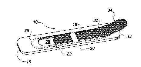
Méthode pour fixer un élément filtrant à une pale de ventilateur. La méthode comporte les étapes suivantes : pratiquer une cavité à l'intérieur de la pale, l'extrémité de la cavité étant orientée vers l'extrémité de la pale et une base orientée vers la base de la pale; réaliser au moins un passage d'écoulement partant d'une surface large de la pale en passant par la cavité pour se rendre jusqu'à la face large opposée de la pale de manière que l'air circule dans la cavité par les passages d'écoulement lorsque la pale bouge; réaliser un orifice d'accès par lequel un élément filtrant est inséré dans la cavité.


Abrégé anglais


There is described a method of securing a filter element
to a blade of a fan. Firstly, form a cavity within a fan
blade. The cavity has a tip end oriented toward a tip of the
fan blade and a root end oriented toward a root of the fan
blade. Secondly, form at least one flow passage extending from
one broad surface of a fan blade through the cavity to an
opposed broad surface of the fan blade, such that air
circulates through the cavity via the flow passages upon
movement of the fan blade. Thirdly, form an access opening
through which a filter element is inserted into the cavity.

Revendications

Note : Les revendications sont présentées dans la langue officielle dans laquelle elles ont été soumises.


THE EMBODIMENTS OF THE INVENTION IN WHICH AN EXCLUSIVE PROPERTY
OR PRIVILEGE IS CLAIMED ARE DEFINED AS FOLLOWS:
1. A method of securing a filter element to a blade of a fan,
comprising the steps of:
a. firstly, forming a cavity within a fan blade, the
cavity having a tip end oriented toward a tip of the fan blade
and a root end oriented toward a root of the fan blade;
b. secondly, forming at least one flow passage extending
from one broad surface of a fan blade through the cavity to an
opposed broad surface of the fan blade, such that air
circulates through the cavity via the at least one flow passage
upon movement of the fan blade; and
c. thirdly, forming an access opening through which a
filter element is inserted into the cavity.
d. fourthly, inserting a filter element through the
access opening into the cavity.
2. The method as defined in Claim 1, means being provided to
prevent the filter element from being propelled back through
the access opening by centrifugal force.
3. The method as defined in Claim 1, the access opening being
a channel extending at an angle through one of the broad
surfaces of the fan blade adjacent one of the tip end and the
root end.
4. The method as defined in Claim 3, the channel being at an
angle of between 5 degrees and 35 degrees.
5. The method as defined in Claim 3, the channel being
adjacent to and spaced inwardly from the tip end while being
angled toward the root end, such that upon rotation of the fan
blade the filter element is propelled by centrifugal force past
the channel until the filter element engages the tip end
thereby maintaining the filter element within the cavity.

6. A method of securing a filter element to a blade of a fan,
comprising the steps of:
a. forming a cavity within a fan blade, the cavity having
a tip end oriented toward a tip of the fan blade and a root end
oriented toward a root of the fan blade;
b. forming flow passages extending from one broad surface
of a fan blade through the cavity to an opposed broad surface
of the fan blade, such that air circulates through the cavity
via the flow passages upon movement of the fan blade; and
c. forming an access channel communicating with the
cavity through one of the broad surfaces of the fan blade
adjacent to and spaced inwardly from the tip end while being
angled between 5 and 35 degrees toward the root end; and
d. inserting a filter element through the access channel
into the cavity, such that upon rotation of the fan blade the
filter element is propelled by centrifugal force past the
access channel until the filter element engages the tip end
thereby maintaining the filter element within the cavity.

Description

Note : Les descriptions sont présentées dans la langue officielle dans laquelle elles ont été soumises.


212~889
. .
The present invention relates to a method of securing a
filter element to a blade of a fan.
BA~K~'"'~UND OF THE INVE.NTION
Fans are employed in many homes to serve the function of
moving stagnant air. The concept of securing a filter element
to a blade of the fan in order to filter air thereby trapping
air borne particles as the fan blade moves is taught in a
number of references.
United States Patent 4,753,573 which issued to McKnight
in 1988 discloses a longitl~inAlly exten~;ng channel member
that i8 fixed by adhesive to a fan blade such that a filter
element is supported in an upstAn~;ng position exten~;ng
outwardly from the fan blade.
United States Patent 4,840,650 which issued to Matherne
in 1989 discloses a filter housing having clip8 which attach
the filter housing to a 1~A~; ng edge of a fan blade.
.::
United States Patent 4,889,543 which issued to Burt in
1989 discloses a method and apparatus in which filter elements
extend between adjacent circumferentially spaced apart fan
blades.
It is readily apparent to an observer when a fan is
equ;ppe~ with one of the described devices. Some types of
fans, for example c~;l;ng fans, serve a collateral decorative
purpose. Great care is taken to make ceiling fans
aesthetically R~peAl ;n~ to the consumer. Anything which
potentially detracts from the aesthetic appearance of the fan
is viewed as being undesirable.
;-t~ '' '''': ~i. ; ;'i'' -' '.";t~ ' '' " "~ "'
r '. ~s ,~
4 ~r. ~ ':.;?~, .",i

~'~ 212~889
SUMMARY OF THE INVENTION
What is required is a method of securing a filter element
to a blade of a fan that is relatively unobtrusive.
According to one aspect of the pre~ent invention there i8
provided a method of securing a filter element to a blade of
a fan which includes the following described steps. Firstly,
form a cavity within a fan blade. The cavity has a tip end
oriented toward a tip of the fan blade and a root end oriented
toward a root of the fan bladel Secondly, form at least one
flow passage ext~n~;ng from one broad surface of a fan hlade
through the cavity to an opposed broad surface of the fan
blade, such that air circulates through the cavity via the flow
passages upon mo~ -nt of the fan blade. Thirdly, form an
access opening through which a filter element is inserted into
the cavity.
.
With the method, as described, the filter element is
h~den within the fan blade. The flow passages can be
attractively arranged to be aesthetically pleasing and in no
way detract from the fan's role as a decorative piece.
Although beneficial results may be obtA;ne~ through the method,
as described, ~epen~;ng upon the positioning of the access
open;ng there may be a ten~sncy for the filter element to be
urged back through the access op~n;ng by centrifugal force.
Even more henef;cial results may, therefore, be obtA;ne~ by
providing means to prevent the filter element from being
propelled back through the access opening by centrifugal force.
In order to address this problem, it is preferred that the
access opening be a chAnn~l exte~;ng at an angle through one
of the broad surfaces of the fan blade adjacent one of the tip
end and the root end. The greater the angle of the access
chAnn~l the less likely centrifugal force will be able to
dislodge the filter element. It is preferred that the access
chAnnel being at an angle of between 5 degrees and 35 degrees.

~ 21~89
~....
Although beneficial results may be obtained through the
use of the method, as described, the Applicant has devised a
simple and cost effective manner to maintain the filter element
in position that can withstand and even benefit from
centrifugal force. Even more beneficial results may be
obtained by placing the access chAnnel adjacent to and spaced
inwardly from the tip end while being angled toward the root
end. Upon rotation of the fan blade the filter element is
propelled by centrifugal force past the access chAnnel until
the filter element engages the tip end thereby maintaining the
filter element within the cavity.
According to another aspect of the invention there is
provided a blade for a fan which includes a blade body having
a tip, a root and opposed broad surfaces. A cavity is provided
within the body. The cavity has a tip end oriented toward the
tip of the body and a root end oriented toward the root of the
body. At least one flow passage extends from one broad surface
of the body through the cavity to the opposed broad surface of
the body, such that air circulates through the cavity via the
flow passages upon mov L of the body. An access ~hAnnel to
the cavity extends through one of the broad surfaces of the
body adjacent to and spaced inwardly from the tip end while
being angled toward the root end. Upon rotation of the body
the filter element is propelled by centrifugal force past the
access chAnn~l until the filter element engages the tip end
thereby maintA; n; ng the filter element within the cavity.
BRIEF ~ ~TPTION OF THE DRAWING8
These and other features of the invention will become more
apparent from the following description in which reference is
made to the Appen~e~ drawings, wherein:
FIGURE 1 is a perspective view of a fan blade constructed
in accordance with the teAch;ngs of the present invention.
~ ,, ~, !,' ." ~~,. ; .~?- '

2 ~ 2 ~ ~ 8 9
FIGU~E 2 is a perspective view of the fan blade
illustrated in FIGURF 1 with a filter element in the process
of being inserted.
FIGUREi 3 is a perspective view of the fan blade
illustrated in FIGURE 1 with the filter element inserted.
FIGURE 4 is a perspective view of the fan blade illustrated in
FIGUREi 1 with the filter element in an operative position.
DE~TT-Fn DESCRIPTION OF THE ~n~r~nA~ EMBODIMENT
The method of securing a filter element to a blade of a
fan, includes the following step~. Firstly, form a cavity
within a fan blade. The cavity having a tip end oriented
toward a tip of the fan blade and a root end oriented toward
a root of the fan blade. Secondly, form at least one flow
passage extending from one broad surface of a fan blade through
the cavity to an opposed broad surface of the fan blade, such
that air circulates through the cavity via the at least one
flow passage upon -v~ of the fan blade. Thirdly, fo_ ;ng
an access openi ng through which a filter element is inserted
into the cavity. In order to successfully follow the
teAch~ngs of the described method, some means must be employed
to pL~Vent centrifugal force exerted upon rotation of the fan
blade~ from dislodging the filter element. The preferred
embodiment which discloses the best mode for putting the method
into practise will now be described.
The preferred ~ t, a blade for a fan generally
identified by reference numeral 10, will now be described with
reference to FIGURES 1 through 4.
Blade 10 includes a blade body 12 having a tip 14, a root
16 and oppo~ed upper broad surface 18 and lower broad surface
20. A cavity 22 is provided within body 12. Cavity 22 has a
tip end 24 oriented toward tip 14 of body 12 and a root end 26
oriented toward root 16 of body 12. A plurality of flow

~' 212~8~9
pas~ages 28 and 30 extend from upper broad surface 18 of body
12 through cavity 22 to lower broad surface 20 of body 12. Air
circulates through cavity 22 via flow passages 28 and 30 upon
v~ -nt of body 12. A channel form access opening
hereinafter referred to as access channel 32 c. n;cates with
cavity 22. Access channel 32 extends through upper broad
surface 18 of body 12. Access ch~nnel 32 is positioned
adjacent to and spaced inwardly from tip end 24. Access
channel 32 is angled toward root end 26. The degree of angle
should be sufficient to impede a filter element 34 from being
withdrawn from cavity 22 via access channel 32, and not so
severe that filter element 34 will be difficult to insert or
become damaged during the process of insertion. An operative
range has been found to be between 5 and 35 degrees.
The use and operation of fan blade 10 will now be
described with reference to FIGURES 1 through 4. FIGURE 1
illustrates fan blade 10 with filter element 34 removed.
Referring to FIGURE 2, filter element 34 is inserted through
access chAnnel 32. Filter element 34 is slid along toward root
end 26 of cavity 22 until it has completely passed through
acce88 opening to assume the position illustrated in FIGURE 3.
Filter element 34 is then slid toward tip end 24 and passed
access open;ng 32 until filter element is in an operative
position illustrated in FIGURE 4. It should be noted that upon
rotation of body 12, filter element 34 is urged by centrifugal
force toward tip end 24 of cavity 22. Filter element 34
engages tip end 24 and is thereby maintained within cavity 22.
Once the end of filter element 34 has pas~ed access ch~nnel 32
toward tip end 24, it is virtually impossible for filter
element 34 to be dislodged by centrifugal force. Centrifugal
force will, in fact, more securely urge filter element 34 into
position. In order to remove filter element 34, filter element
34 is drawn back from tip end 24 and is threaded back through
access op~ni n~ 32.

~ 2~2~88~ ~ ~
.,,................................................................ ;
6 . : .
It will be apparent to one skilled in the art that
modifications may be made to the illustrated~ t without
departing from the spirit and scope of the invention as defined
by the claims.
:
' ~-
: ' ~ '.:
'.'~: ' ::
.. ~:, .
.,~; .
,: . ~.... .: .
:
~ :~ : :'
: , .
:.
... ' .
, . . ... .
., ~ ' .: ~ .: :'
"
. i:,,, ~.:,.. .
, ~., -... ~.
' " ' ~','"
~': ,, , .. , .: .
. . .
':' "'' ",
. ~ '',,'' ''',,'':',"'
' ' .', ,, ' ', ',
:::':: ' .: '."
': '' ' ~ ~ .,:': '
' :' ,'.
', ' ' ' . .
~ 3 ~

Dessin représentatif
Une figure unique qui représente un dessin illustrant l'invention.
États administratifs

2024-08-01 : Dans le cadre de la transition vers les Brevets de nouvelle génération (BNG), la base de données sur les brevets canadiens (BDBC) contient désormais un Historique d'événement plus détaillé, qui reproduit le Journal des événements de notre nouvelle solution interne.

Veuillez noter que les événements débutant par « Inactive : » se réfèrent à des événements qui ne sont plus utilisés dans notre nouvelle solution interne.

Pour une meilleure compréhension de l'état de la demande ou brevet qui figure sur cette page, la rubrique Mise en garde , et les descriptions de Brevet , Historique d'événement , Taxes périodiques et Historique des paiements devraient être consultées.

Historique d'événement

Description Date
Inactive : Périmé (brevet - nouvelle loi) 2014-06-01
Inactive : Lettre officielle 2011-05-03
Exigences relatives à la révocation de la nomination d'un agent - jugée conforme 2011-05-03
Exigences relatives à la nomination d'un agent - jugée conforme 2011-05-03
Inactive : Lettre officielle 2011-04-28
Requête visant une déclaration du statut de petite entité reçue 2008-04-29
Déclaration du statut de petite entité jugée conforme 2008-04-29
Inactive : CIB de MCD 2006-03-11
Inactive : TME en retard traitée 1999-07-09
Lettre envoyée 1999-06-01
Accordé par délivrance 1998-07-28
Inactive : CIB enlevée 1998-05-22
Inactive : CIB en 1re position 1998-05-22
Inactive : Taxe finale reçue 1998-03-19
Préoctroi 1998-03-19
Un avis d'acceptation est envoyé 1997-09-23
Lettre envoyée 1997-09-23
Un avis d'acceptation est envoyé 1997-09-23
Inactive : Renseign. sur l'état - Complets dès date d'ent. journ. 1997-09-15
Inactive : Dem. traitée sur TS dès date d'ent. journal 1997-09-15
Inactive : CIB attribuée 1997-08-11
Inactive : CIB enlevée 1997-08-11
Inactive : CIB attribuée 1997-08-11
Inactive : CIB enlevée 1997-08-11
Inactive : CIB attribuée 1997-08-11
Inactive : CIB enlevée 1997-08-11
Inactive : CIB attribuée 1997-08-11
Inactive : CIB enlevée 1997-08-11
Inactive : CIB attribuée 1997-08-11
Inactive : CIB enlevée 1997-08-11
Inactive : CIB attribuée 1997-08-11
Inactive : CIB enlevée 1997-08-11
Inactive : CIB en 1re position 1997-08-11
Inactive : Approuvée aux fins d'acceptation (AFA) 1997-08-07
Demande publiée (accessible au public) 1994-12-16
Exigences pour une requête d'examen - jugée conforme 1994-10-11
Toutes les exigences pour l'examen - jugée conforme 1994-10-11

Historique d'abandonnement

Il n'y a pas d'historique d'abandonnement

Taxes périodiques

Le dernier paiement a été reçu le 1998-05-26

Avis : Si le paiement en totalité n'a pas été reçu au plus tard à la date indiquée, une taxe supplémentaire peut être imposée, soit une des taxes suivantes :

  • taxe de rétablissement ;
  • taxe pour paiement en souffrance ; ou
  • taxe additionnelle pour le renversement d'une péremption réputée.

Les taxes sur les brevets sont ajustées au 1er janvier de chaque année. Les montants ci-dessus sont les montants actuels s'ils sont reçus au plus tard le 31 décembre de l'année en cours.
Veuillez vous référer à la page web des taxes sur les brevets de l'OPIC pour voir tous les montants actuels des taxes.

Historique des taxes

Type de taxes Anniversaire Échéance Date payée
Requête d'examen - petite 1994-10-11
Taxe finale - petite 1998-03-19
TM (demande, 4e anniv.) - petite 04 1998-06-01 1998-05-26
TM (brevet, 5e anniv.) - petite 1999-06-01 1999-07-09
Annulation de la péremption réputée 1999-06-01 1999-07-09
TM (brevet, 6e anniv.) - petite 2000-06-01 2000-05-19
TM (brevet, 7e anniv.) - petite 2001-06-01 2001-05-18
TM (brevet, 8e anniv.) - petite 2002-06-03 2002-05-28
TM (brevet, 9e anniv.) - petite 2003-06-02 2003-05-30
TM (brevet, 10e anniv.) - petite 2004-06-01 2004-04-01
TM (brevet, 11e anniv.) - petite 2005-06-01 2005-04-13
TM (brevet, 12e anniv.) - petite 2006-06-01 2006-05-10
TM (brevet, 13e anniv.) - petite 2007-06-01 2007-05-02
TM (brevet, 14e anniv.) - petite 2008-06-02 2008-04-29
TM (brevet, 15e anniv.) - petite 2009-06-01 2009-05-27
TM (brevet, 16e anniv.) - petite 2010-06-01 2010-03-11
TM (brevet, 17e anniv.) - petite 2011-06-01 2011-03-18
TM (brevet, 18e anniv.) - petite 2012-06-01 2012-05-30
TM (brevet, 19e anniv.) - petite 2013-06-03 2013-05-03
Titulaires au dossier

Les titulaires actuels et antérieures au dossier sont affichés en ordre alphabétique.

Titulaires actuels au dossier
WILLIAM KURYLIW
Titulaires antérieures au dossier
S.O.
Les propriétaires antérieurs qui ne figurent pas dans la liste des « Propriétaires au dossier » apparaîtront dans d'autres documents au dossier.
Documents

Pour visionner les fichiers sélectionnés, entrer le code reCAPTCHA :


Pour visualiser une image, cliquer sur un lien dans la colonne description du document. Pour télécharger l'image (les images), cliquer l'une ou plusieurs cases à cocher dans la première colonne et ensuite cliquer sur le bouton "Télécharger sélection en format PDF (archive Zip)" ou le bouton "Télécharger sélection (en un fichier PDF fusionné)".

Liste des documents de brevet publiés et non publiés sur la BDBC .

Si vous avez des difficultés à accéder au contenu, veuillez communiquer avec le Centre de services à la clientèle au 1-866-997-1936, ou envoyer un courriel au Centre de service à la clientèle de l'OPIC.


Description du
Document 
Date
(aaaa-mm-jj) 
Nombre de pages   Taille de l'image (Ko) 
Revendications 1998-06-08 2 72
Abrégé 1995-05-26 1 84
Revendications 1995-05-26 2 184
Dessins 1995-05-26 2 182
Description 1995-05-26 6 613
Revendications 1997-05-20 2 72
Revendications 1998-05-31 2 72
Dessin représentatif 1998-07-23 1 13
Avis du commissaire - Demande jugée acceptable 1997-09-22 1 164
Avis concernant la taxe de maintien 1999-06-28 1 179
Quittance d'un paiement en retard 1999-07-14 1 172
Avis concernant la taxe de maintien 1999-06-28 1 179
Taxes 2003-05-29 1 25
Taxes 2002-05-27 1 27
Correspondance 1998-03-18 1 46
Taxes 1998-05-25 1 37
Taxes 1999-07-08 1 40
Taxes 2004-03-31 1 30
Taxes 2005-04-12 1 26
Taxes 2006-05-09 1 26
Taxes 2007-05-01 1 27
Correspondance 2008-04-28 2 67
Taxes 2008-04-28 2 67
Taxes 2009-05-26 1 200
Taxes 2010-03-10 1 200
Correspondance 2011-03-30 3 133
Correspondance 2011-04-27 1 12
Correspondance 2011-05-02 1 19
Correspondance 1994-11-09 1 59
Correspondance 1997-04-01 2 63
Taxes 1997-04-23 1 44
Taxes 1996-03-14 1 42