Note: Descriptions are shown in the official language in which they were submitted.
212~93
TILTING AND SLIDING 8URFACB ASSBMBLY FOR A TABLB
BACKGROUND AND SUMMARY OF THE INVENTION
This invention relates to a table in the nature
of a worktable adapted for use with a computer or the
like, and more particularly to a table including a mov-
able surface for supporting the keyboard of a computer.
Worktables for supporting a computer are well
known. Many workstations or tables for supporting a
computer include a pad or surface for supporting the
computer keyboard, and it is known to provide such a
surface which is movable to varying positions according
to individual user requirements.
It is an object of the present invention to
provide a keyboard surface for use in combination with a
worktable which is adapted to be received within an
opening defined by the worktable, and which can be slid
inwardly and outwardly relative to the table and moved to
varying angular positions relative to the table. It is a
further object of the invention to provide a tilting and
sliding keyboard surface mechanism which is simple in its
construction and operation, yet which provides highly
satisfactory movement of the keyboard surface in response
to user requirements. Another object of the invention is
to provide a tilting and sliding mechanism for a keyboard
surface which can be easily adapted for use with existing
table construction.
In accordance with the invention, a movable
surface assembly is adapted for use with a table which
includes a pair of spaced vertically adjustable hori-
zontal surfaces defining an opening therebetween withinwhich the movable surface is received. The table further
includes at least a pair of legs and a cross-member
extending below and supporting the horizontal surfaces.
The cross-member preferably extends across the opening,
and is interconnected with the legs for supporting the
horizontal surfaces. The invention provides a movable
surface disposed within the opening, a bracket assembly
2124893
2 --
engageable with the cross-member and secured to the
movable surface, a manually operable pivot mechanism and
a manually operable slide mechanism, both of which are
interposed between the bracket assembly and the movable
surface. The pivot mechanism provides movement of the
movable surface about a substantially horizontal pivot
axis relative to the horizontal surfaces, and the slide
mechanism provides sliding inward-outward movement of the
movable surface relative to the horizontal surface. The
bracket assembly is defined by a first bracket stationar-
ily mounted to the cross-member and a second bracket
stationarily mounted to the movable surface. The pivot
mechanism is interposed between the first and second
brackets. A selectively operable tilt lock mechanism is
interconnected between the first and second brackets for
selectively locking the position of the second bracket
relative to the first bracket to selectively lock the
position of the movable surface relative to the fixed
surface. The slide mechanism is in the form of a pair of
laterally extending guide members secured to the second
bracket. The guide members extend in an inward-outward
direction parallel to the direction of movement of the
movable surface. A slide member is mounted to the mov-
able surface and defines channel structure within which
the guide members are received. The guide members are
defined by the ends of a plate member which is mounted to
the second bracket. A bearing member is interposed
between each guide member and the slide member channel
structure. Each bearing member is fixedly engaged with
one of the guide members, and is preferably in the form
of a U-shaped member secured to each guide member. The
slide member channel structure is preferably in the form
of a pair of facing channels formed on a slide bracket
member mounted to the underside of the movable surface,
within a recess formed therein. The bearing members
facilitate relative inward-outward movement between the
2124893
_ - 3 -
slide and the second bracket, and thereby between the
movable surface and the horizontal surfaces.
Various other features, objects and advantages
of the invention will be made apparent from the following
description taken together with the drawings.
BRIEF DESCRIPTION OF THE DRAWINGS
The drawings illustrate the best mode presently
contemplated of carrying out the invention.
In the drawings:
Fig. 1 is an isometric view of a table incorpo-
rating the tilting and sliding surface mechanism of the
invention;
Fig. 2 is a partial isometric view of a portion
of the table of Fig. 1, showing the movable surface moved
outwardly relative to the horizontal surfaces;
Fig. 3 is a view similar to Fig. 2, showing the
movable surface in a tilted position relative to the
horizontal surfaces;
Fig. 4 is a transverse sectional view through
the movable surface and a portion of the fixed surface,
showing the tilting and sliding mechanism interconnecting
the movable surface with the fixed surface, and in which
the movable surface is in its inwardmost horizontal
position;
Fig. 5 is a view similar to Fig. 4, showing the
movable surface in a tilted position; and
Fig. 6 is a partial sectional view taken along
line 6-6 of Fig. 4.
DETAILED DESCRIPTION OF THE INVENTION
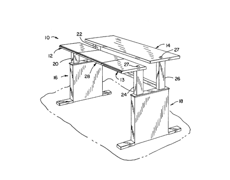
Referring to Fig. 1, a split-surface worktable
10 generally includes a pair of horizontal front surfaces
12, 13, a rear surface 14, and a pair of leg assemblies
16, 18. Leg assembly 16 includes a front leg 20 and a
rear leg 22, and leg assembly 18 includes a front leg 24
and a rear leg 26. Front legs 20, 24 support front
surfaces 12, 13, respectively, and rear legs 22, 26
support rear surface 14. Leg assemblies 16, 18 also
21248!3~
_ - 4 -
include a crank-type adjustable height mechanism inter-
connected with each of its respective front and rear legs
for providing adjustability in the elevation of front
surface 12 and rear surface 14 relative to the floor.
Openings 27 are formed in surfaces 13, 14, and the crank-
type height adjustment mechanisms extend through opening
27.
The components and assembly described above are
generally known in the art, and are commercially avail-
able from Krueger International, Inc. of Green Bay,
Wisconsin, the assignee of the present application, under
its designation WorkZone and/or DataBord.
In accordance with the invention, an adjustable
or movable surface 28 is interconnected with front sur-
face 12 and is received within an opening or space 29
front surfaces 12 and 13. Movable surface 28 is particu-
larly well suited for supporting a computer keyboard or
the like, and rear surface 14 is well suited for support-
ing a computer monitor.
Movable surface 28 is interconnected with a
tilting and sliding mechanism, shown generally at 30 in
Figs. 4-6, which provides movement of movable surface 28
in an inward-outward direction and about a horizontal
tilt axis. Fig. 2 illustrates movable surface 28 in its
outwardmost position in which movable surface 28 is slid
outwardly relative to front surfaces 12 and 13. Fig. 3
illustrates movable surface 28 tilted about a horizontal
tilt axis relative to front surfaces 12 and 13. Prefera-
bly, movable surface 28 may be movable outwardly a dis-
tance of approximately 5 inches, as shown in Fig. 2, andmay be tiltable approximately 15~ from horizontal in
either a forward tilt direction, as shown in Fig. 3, or
in a rearward tilt direction.
Referring to Figs. 4-6, tilting/sliding mecha-
nism 30 generally includes a fixed bracket assembly 32and a movable bracket assembly 34. Fixed bracket assem-
bly 32 is mounted to a cross-member 36 which extends
~ 212~89~
_ - 5
below and between horizontal surfaces 12 and 13 between
legs 20, 24 through space 29 within which movable surface
28 is received. Movable bracket assembly 34 is mounted
to the underside of movable surface 28.
Fixed bracket assembly 32 includes a plate 38
engageable with the top of cross-member 36, and a clam
shell member 40 engageable with the bottom of cross-
member 36. A series of threaded screws 42 interconnect
clam shell member 40 with plate 38 for clamping fixed
bracket assembly 32 to cross-member 36.
A pair of bracket arms 44, 46 are welded to the
ends of plate 38. Arms 44, 46 define down turnedforward
ends, and aligned forward openings 48, 50 (Fig. 6) are
formed in the forward end portions of arms 44, 46, re-
spectively. Aligned rear openings 52, 54 (Fig. 6) are
formed in the rearward portion of arms 44, 46, respec-
tively.
Movable bracket assembly 34 includes a pair of
side plates 56, 58 rigidly mounted to and extending
downwardly from an upper guide plate 60. A cross-member
(not shown) extends between and interconnects side plate
56, 58, and guide plate 60 is fixed thereto such as by
welding or the like. A slide member 62 is fixed to the
underside of movable surface 28 within a recess 64 formed
therein, such as by a series of screws 66.
Guide plate 60 is bent at its ends to define
longitudinally extending lateral end portions 68, 70. U-
shaped nylon bearing members 72, 74 are fixedly engaged
with guide plate end portions 68, 70, respectively.
Illustratively, spaced openings (not shown) may be formed
in guide plate end portions 68, 70, and bearing members
72, 74 are formed with protrusions which snap into the
spaced openings in guide plate end portions 68, 70 to
secure bearing members 72, 74 thereto and to prevent
longitudinal movement between bearing members 72, 74 and
guide plate 60.
2124893
-- 6 --
Slide member 62 includes a pair of facing
channels 76, 78 at its ends. Channels 76, 78 are shaped
so as to correspond to the outer shape of bearing members
72, 74, which are received within channels 76, 78, re-
spectively. With this construction, movable surface 28can be moved inwardly and outwardly relative to movable
bracket assembly 34 in response to exertion of a manual
inward-outward force exerted by the user, with channels
76, 78 moving over bearing members 72, 74, respectively.
A stop member 80 is mounted to guide plate 60, and a
plate bumper 81 is screwed into the underside of movable
surface 28 to prevent movable surface 28 from being drawn
off of guide plate 60.
Movable bracket assembly 34 is pivotably inter-
connected with fixed bracket assembly 32 by means of apivot rod 82 which extends through openings 52, 54 in
fixed bracket side plates 44, 46, respectively, and
through aligned openings 84, 86 formed in movable bracket
side plates 56, 58, respectively. Caps 88 are engaged
with the ends of pivot rod 82 to fix pivot rod 82 in
position relative to fixed bracket assembly 32 and mov-
able bracket assembly 34.
A manually operable tilt lock mechanism, shown
generally at 86, is interconnected between fixed bracket
arms 44, 46 and movable bracket side plates 56, 58,
respectively. Tilt lock mechanism 86 includes a sleeve
88 which defines a longitudinal passage therethrough.
The ends of sleeve 88 bear against the facing surfaces of
fixed bracket arms 44, 46. The passage in sleeve 88 is
aligned with openings 48, 50 formed in fixed bracket arms
44, 46, respectively.
Arcuate slots 90, 92 are formed in movable
bracket side plates 56, 58, respectively. A locking bolt
94 extends through the passage in sleeve 88 and through
openings 48, 50 in fixed bracket arms 44, 46, respective-
ly. Bolt 94 also extends through slots 90, 92, and
includes a head 96 which bears against the outer surface
212~893
_ 7
of movable bracket side plate 58. Bolt 94 further in-
cludes a threaded shank 98 which extends through slot 90
in side plate 56, extending outwardly therefrom. A nut
member 100, which includes a handle 102, is threadedly
engaged with threaded shank 98. A washer 104 is inter-
posed between nut member 100 and movable bracket side
plate 56. Bolt head 96 extends through slot 92, and
engages movable bracket side plate 58 on either side of
slot 92.
In operation, tilting and sliding mechanism 30
functions as follows to provide tilting and sliding
movement of movable surface 28 relative to horizontal
surfaces 12 and 13. To draw movable surface 28 forward-
ly, the user grasps the underside of surface 28 between
movable bracket side plates 56, 58, where a lip is formed
by recess 64. The user exerts a pull-out motion, and
surface 28 is drawn outwardly by sliding movement of
slide member channels 76, 78 over bearings 72, 74, re-
spectively. To move movable surface 28 inwardly, the
user exerts a push-in force on movable surface 28 and
sliding movement again occurs between slide member chan-
nels 76, 78 and bearings 72, 74, respectively. If de-
sired, a slide lock can be manually operated to selec-
tively lock the sliding position of movable surface 28.
Illustratively, such a lock could be in the form of a
threaded screw fixed to either or both of guide portions
68, 70, extendirg downwardly therefrom through longitudi-
nal slots formed in the lower wall of channels 76, 78. A
manually operable nut is engaged with each threaded
screw, and selectively bears against the lower wall of
channels 76, 78 to selectively clamp channels 76, 78 to
guide portions 68, 70, respectively.
To adjust the tilting position of movable
surface 28, the user rotates tilt lock mechanism nut
member 100 using handle 102 to release engagement between
movable bracket side plates 56, 58 and fixed bracket arms
44, 46, respectively, and moves movable surface 28 to a
212~893
-
-- 8 --
desired tilt position by exerting an appropriate upward
of downward force on the forward or rearward end of
movable surface 28, as desired. When the desired posi-
tion of movable surface 28 is attained, the user tightens
nut member 100 using handle 102. This functions to draw
bolt 94 leftwardly (Fig. 6), to clamp movable bracket
side plate 58 and fixed bracket arm 46 together between
bolt head 96 and sleeve 88, and to clamp movable bracket
side plate 56 and fixed bracket arm 44 together between
washer 104 and sleeve 88. This frictional clamping of
movable bracket assembly 34 to fixed bracket assembly 32
selectively maintains movable surface 28 in its desired
tilting position.
As can be appreciated, the sliding movement of
movable surface 28 is independent of the tilting of
movable surface 28. That is, surface 28 can be slid
inwardly and outwardly at any tilting position, and
conversely the tilting position of movable surface 28 can
be changed at any inward/outward position of surface 28.
In addition, tilting/sliding mechanism 30 and
movable surface 28 can easily be retrofit onto an exist-
ing split-surface worktable by replacing an existing
horizontal front surface with lateral horizontal surfaces
12 and 13 with space 29 therebetween, clamping tilt-
ing/sliding mechanism 30 to cross-member 40 using plate
38 and clam shell member 40, and then mounting movable
surface 28 to slide member 62 using screws 66.
Various alternatives and embodiments are con-
templated as being within the scope of the following
claims particularly pointing out and distinctly claiming
the subject matter regarded as the invention.