Language selection

Search

Patent 2124997 Summary

Third-party information liability

Some of the information on this Web page has been provided by external sources. The Government of Canada is not responsible for the accuracy, reliability or currency of the information supplied by external sources. Users wishing to rely upon this information should consult directly with the source of the information. Content provided by external sources is not subject to official languages, privacy and accessibility requirements.

Claims and Abstract availability

Any discrepancies in the text and image of the Claims and Abstract are due to differing posting times. Text of the Claims and Abstract are posted:

  • At the time the application is open to public inspection;
  • At the time of issue of the patent (grant).
(12) Patent: (11) CA 2124997
(54) English Title: EXPOSURE DEVICE
(54) French Title: DISPOSITIF D'EXPOSITION
Status: Expired and beyond the Period of Reversal
Bibliographic Data
(51) International Patent Classification (IPC):
  • G03B 27/00 (2006.01)
  • G03B 27/60 (2006.01)
(72) Inventors :
  • TSUJI, MASAAKI (Japan)
(73) Owners :
  • NORITSU KOKI CO., LTD.
(71) Applicants :
  • NORITSU KOKI CO., LTD. (Japan)
(74) Agent: SMART & BIGGAR LP
(74) Associate agent:
(45) Issued: 1999-03-09
(22) Filed Date: 1994-06-02
(41) Open to Public Inspection: 1994-12-09
Examination requested: 1996-02-13
Availability of licence: N/A
Dedicated to the Public: N/A
(25) Language of filing: English

Patent Cooperation Treaty (PCT): No

(30) Application Priority Data:
Application No. Country/Territory Date
5-137155 (Japan) 1993-06-08

Abstracts

English Abstract


An exposure device for sucking photosensitive
materials of different widths on an exposure table. A
suction belt, driven by a motor, is formed with a plurality
of suction holes uniformly. On the back of the suction
belt is mounted a suction box with a belt support plate
which is formed with a plurality of suction holes. A pair
of adjusting plates are attached to the belt support plate
on its back. By adjusting the position of the adjusting
plates in a width direction, the suction holes in the
outermost rows at both sides are opened and closed. Thus,
the suction width for the suction belt can be adjusted
according to the width of the photosensitive material.


French Abstract

Dispositif d'exposition pour aspirer des matériaux photosensibles de différentes largeurs sur une table d'exposition. Une courroie d'aspiration, entraînée par un moteur, est formée uniformément de nombreux orifices d'aspiration. Une caisse d'aspiration est montée à l'arrière de la courroie d'aspiration avec une plaque de support de courroie formée de nombreux orifices d'aspiration. Deux plaques de réglage sont fixées à l'arrière de la plaque de support de courroie. En réglant la position des plaques de réglage dans le sens de la largeur, les orifices d'aspiration, situés dans les rangées les plus à l'extérieur sur les deux côtés, sont ouverts et fermés. On peut ainsi régler la largeur d'aspiration de la courroie selon la largeur du matériau photosensible.

Claims

Note: Claims are shown in the official language in which they were submitted.

THE EMBODIMENTS OF THE INVENTION IN WHICH AN EXCLUSIVE
PROPERTY OR PRIVILEGE IS CLAIMED ARE DEFINED AS FOLLOWS.
1. An exposure device, comprising:
a suction belt having a plurality of suction holes
therein arranged in a plurality of rows that extend in a
longitudinal direction of said suction belt;
a suction box;
an exposure table comprising a belt support plate
connected with said suction box, said belt support plate
having a front side for supporting said suction belt, a
plurality of suction holes formed therein in a plurality of
rows that extend in the longitudinal direction of said suction
belt for communication with said suction holes of said suction
belt, and a back side; and
an adjusting plate movably mounted on said back side of
said belt support plate so as to be movable between a closed
position in which some of said suction holes of said belt
support plate are closed and an open position in which said
suction holes of said belt support plate that are closed in
said closed position are open.
2. The exposure device of claim 1, and further comprising a
moving means for moving said adjusting plate between said open
and closed positions in a width direction of said belt support
plate, the width direction being perpendicular to the
longitudinal direction.

3. The exposure device of claim 2, wherein said moving means
comprises a contact element connected with said adjusting
plate, a cam, a motor for driving said cam and a spring
biasing said contact element against said cam.
4. The exposure device of claim 3, and further comprising a
second adjusting plate connected with the first said adjusting
plate, both said adjusting plates extending in said
longitudinal direction and being separated by a plurality of
rows of said suction holes in said belt support plate.
5. The exposure device of claim 1, wherein said adjusting
plate comprises a plurality of holes therein that are aligned
with said suction holes of said belt support plate in said
open position and are misaligned with said suction holes of
said belt support plate in said closed position.
6. The exposure device of claim 5, wherein said adjusting
plate is wider in a direction perpendicular to said
longitudinal direction that the distance in the direction
perpendicular to said longitudinal direction between two rows
of said plurality of suction holes in said belt support plate.
7. The exposure device of claim 1, and further comprising a
blower connected with said suction box for evacuating said
suction box.

Description

Note: Descriptions are shown in the official language in which they were submitted.


;~ 2124997
EXPOSURE DEVICE
This invention relates to an exposure device used to
print/expose a negative image on a negative film on a
photosensitive material.
As an exposure device, the one shown in Fig. 5 is
known. In this exposure device, a photosensitive material
P drawn from a roll R is cut to a predetermined size by a
cutter device 30. The photosensitive material Pl, which is
now cut off, is supported on an exposure table 20. A
negative film F is illuminated by a light source 21 to
print/expose the negative image thereon on the
photosensitive material Pl through a printing lens 22.
As shown in Fig. 6, the exposure table 20 in the
exposure device comprises a motor 23, an endless suction
belt 24 driven by the motor 23 and formed with a plurality
of suction holes 2S, a suction box 26 having a support
plate 27 formed with a plurality of suction holes 28, which
are communicable with the suction holes 25 of the suction
belt 24, and a blower 29 for sucking the interior of the
suction box 26. The photosensitive material Pl is sucked
and kept in its position by a suction force applied through
the suction holes 28 and the suction holes 25 until it is
fed to the exposure stage to be printed and exposed.
Furthermore, the photosensitive material Pl after

'_ ~12~9 97;
printed and exposed is fed from the exposure table 20 to a
developing unit (not shown) by the movement of the suction
belt 24.
In such a conventional exposure device, the suction force
is applied through all the suction holes 25 of the suction
belt face 24a regardless of the width of the photosensitive
material P1. If it has a small width, so many suction holes
25 are open that the air is also sucked into the suction box
26 through the suction holes 25.
Thus, the suction force per unit surface area of the
photosensitive material P1 becomes so weak that it is not
sucked enough and gets afloat. This will cause a problem of
fuzziness.
If the suction force is set based on the smallest width
of the photosensitive material P1 to solve this problem, it is
necessary to provide a blower 29 of an extremely large
capacity, resulting another problem of noise. Moreover, the
suction belt 24 has a larger transfer resistance, which will
increase the size of the motor 23 as well as the cost.
It is an object to provide an exposure device which
obviates the aforementioned problems and which makes it
possible to reduce the size of the blower and the motor.
According to the present invention, there is provided an
exposure device, comprising: a suction belt having a
plurality of suction holes therein arranged in a plurality of
rows that extend in a longitudinal direction of said suction
belt; a suction box; an exposure table comprising a belt
'P~

2 ~ 24997
-
support plate connected with said suction box, said belt
support plate having a front side for supporting said suction
belt, a plurality of suction holes formed therein in a
plurality of rows that extend in the longitudinal direction of
said suction belt for communication with said suction holes of
said suction belt, and a back side; and an adjusting plate
movably mounted on said back side of said belt support plate
so as to be movable between a closed position in which some of
said suction holes of said belt support plate are closed and
an open position in which said suction holes of said belt
support plate that are closed in said closed position are
open.
In the exposure device according to the present
invention, since the suction width of the suction belt is
adjustable according to the width of the photosensitive
material, it can be sucked and fed while keeping the adjusted
state.
Thus, even if the suction force is set based on the
photosensitive material having a largest width, the
photosensitive material of a smallest width can be sucked
reliably. In other words, a photosensitive material of any
kind can be sucked stably.
Moreover, since the suction force can be set based on the
photosensitive material having a largest width, a blower and a
motor for feeding the suction belt of a small size may be
used.

2 ~
Other features and objects of the present invention will
become apparent from the following description made with
reference to the accompanying drawings, in which:
r~

2124997
-
embodiment of the exposure table according to the present
invention;
Fig. 2 is a sectional view taken along II - II of
Fig. 1;
Fig. 3 is a sectional view taken along III - III of
Fig. l;
Fig. 4 is a sectional view showing how the suction
width is adjusted;
Fig. 5 is a schematic view of the exposure device;
and
Fig. 6 is a partially cutaway perspective view of a
prior art exposure table.
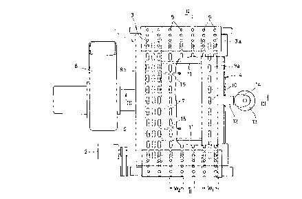
An exposure table 1 comprises an endless suction belt
3 driven by a motor 2, and a suction box 4 for supporting a
suction belt 3a at its carrier side.
The suction belt 3 is formed with a plurality of
suction holes 5 spaced apart predetermined intervals with
one another in its feed direction. They are provided in a
plurality of rows in a width direction of the suction belt
3. In the embodiment, the suction holes 5 are provided in
seven rows.
The suction box 4 has a belt support plate 6 for
supporting the suction belt 3a at the carrier side. The
belt support plate 6 is formed with a plurality of suction
holes 7 spaced apart predetermined intervals with one

2124997
another in a feed direction. They are provided in a
plurality of rows in a width direction of the suction belt
3. The interval between the rows of the suction holes 7 in
the belt support plate 6 is the same as that of the suction
holes 5 in the suction belt 3 so that the rows of the
suction holes 5 and 7 are aligned with each other.
Further, the suction holes 7 are elongated in a feed
direction of the suction belt 3. Thus, even while the
suction belt 3 is being fed, any of the plurality of
suction holes 5 formed in the suction belt 3 will
communicate with one of the suction holes 7.
A blower 8 is connected to the suction box 4 to suck
the interior of the suction box 4.
A pair of adjusting plate 9a and 9b in the form of
strips are attached to both sides of the belt support plate
6 from its back. Their width Wl is larger than the
interval W2 between the adjacent rows of the suction holes
7.
At the center of the adjusting plates 9a and 9b are
formed a plurality of elongated holes 10 spaced apart
predetermined intervals with one another in their
longitudinal direction. By moving the adjusting plates 9a
and 9b in a width direction, the elongated holes 10 will be
aligned with the suction holes 7.
The adjusting plates 9a and 9b are coupled to each

2124997
,.",
other by a link 11. To the adjusting plate 9a is mounted a
contact element 12 which slidably extends through a side
plate of the suction box 4 and is kept into contact with a
cam 14 driven by a motor 13.
Springs 15 are coupled to the other adjusting plate
9b. The contact element 12 is urged against the cam 14 by
the bias of the spring 15.
Fig. 3 shows a state in which the elongated holes 10
formed in the adjusting plates 9a and 9b and are not in
alignment with the suction holes 7 in the belt support
plate 6. In this state, the suction holes 7 in the
outermost two rows on both sides are closed by the
adjusting plates 9a and 9b.
Therefore, if the blower 8 is activated, the suction
force will be applied to the suction holes 7 in the central
three rows, and thus only to the suction holes 5 which
communicate with these suction holes 7. A1 in Fig. 3 shows
the suction width when the adjusting plates 9a and 9b close
the suction holes 7 in the outermost two rows at both
s ldes .
From this state shown in Fig. 3, the cam 14 is driven
by the motor 13 to move the adjusting plates 9a and 9b in a
width direction of the belt support plate 6. The motor 13
is stopped as soon as the elongated holes 10 of the
adjusting plates 9a and 9b have come into alignment with

2124997
',~
the suction holes 7 of the belt support plate 6. As shown
in Fig. 4, all the suction holes 7 are now open, so that
the suction force is applied through the suction holes 5
communicating with the suction holes 7. A2 shows the
suction width in this state.
By moving the adjusting plates 9a and 9b widthwise,
the suction width acting on the suction belt 3a at the
carrier side can be adjusted in two steps. Thus, by
adjusting the suction width according to the width of the
photosensitive material P1 fed by the suction belt 3, the
photosensitive material P1 of different widths can be
sucked stably.

Representative Drawing
A single figure which represents the drawing illustrating the invention.
Administrative Status

2024-08-01:As part of the Next Generation Patents (NGP) transition, the Canadian Patents Database (CPD) now contains a more detailed Event History, which replicates the Event Log of our new back-office solution.

Please note that "Inactive:" events refers to events no longer in use in our new back-office solution.

For a clearer understanding of the status of the application/patent presented on this page, the site Disclaimer , as well as the definitions for Patent , Event History , Maintenance Fee  and Payment History  should be consulted.

Event History

Description Date
Inactive: IPC from MCD 2006-03-11
Time Limit for Reversal Expired 2002-06-03
Letter Sent 2001-06-04
Grant by Issuance 1999-03-09
Inactive: Final fee received 1998-11-17
Pre-grant 1998-11-17
Notice of Allowance is Issued 1998-10-01
Letter Sent 1998-10-01
Inactive: Application prosecuted on TS as of Log entry date 1998-09-21
Inactive: Status info is complete as of Log entry date 1998-09-21
Inactive: First IPC assigned 1998-08-10
Inactive: IPC removed 1998-08-10
Inactive: IPC assigned 1998-08-10
Inactive: Approved for allowance (AFA) 1998-08-10
Request for Examination Requirements Determined Compliant 1996-02-13
All Requirements for Examination Determined Compliant 1996-02-13
Application Published (Open to Public Inspection) 1994-12-09

Abandonment History

There is no abandonment history.

Maintenance Fee

The last payment was received on 1998-03-20

Note : If the full payment has not been received on or before the date indicated, a further fee may be required which may be one of the following

  • the reinstatement fee;
  • the late payment fee; or
  • additional fee to reverse deemed expiry.

Patent fees are adjusted on the 1st of January every year. The amounts above are the current amounts if received by December 31 of the current year.
Please refer to the CIPO Patent Fees web page to see all current fee amounts.

Fee History

Fee Type Anniversary Year Due Date Paid Date
MF (application, 4th anniv.) - standard 04 1998-06-02 1998-03-20
Final fee - standard 1998-11-17
MF (patent, 5th anniv.) - standard 1999-06-02 1999-04-29
MF (patent, 6th anniv.) - standard 2000-06-02 2000-05-18
Owners on Record

Note: Records showing the ownership history in alphabetical order.

Current Owners on Record
NORITSU KOKI CO., LTD.
Past Owners on Record
MASAAKI TSUJI
Past Owners that do not appear in the "Owners on Record" listing will appear in other documentation within the application.
Documents

To view selected files, please enter reCAPTCHA code :


To view images, click a link in the Document Description column. To download the documents, select one or more checkboxes in the first column and then click the "Download Selected in PDF format (Zip Archive)" or the "Download Selected as Single PDF" button.

List of published and non-published patent-specific documents on the CPD .

If you have any difficulty accessing content, you can call the Client Service Centre at 1-866-997-1936 or send them an e-mail at CIPO Client Service Centre.


Document
Description 
Date
(yyyy-mm-dd) 
Number of pages   Size of Image (KB) 
Abstract 1995-04-13 1 107
Drawings 1995-04-13 5 249
Claims 1995-04-13 1 52
Description 1995-04-13 7 423
Description 1998-07-14 8 210
Claims 1998-07-14 2 67
Drawings 1998-07-14 5 75
Representative drawing 1999-03-01 1 11
Commissioner's Notice - Application Found Allowable 1998-09-30 1 163
Maintenance Fee Notice 2001-07-02 1 178
Correspondence 1998-11-16 1 39
Maintenance fee payment 1997-02-27 1 54
Maintenance fee payment 1995-02-28 1 59
Prosecution correspondence 1994-06-01 8 244
Courtesy - Office Letter 1996-03-05 1 53
Correspondence related to formalities 1996-02-12 1 45
Prosecution correspondence 1996-05-08 1 50
Prosecution correspondence 1998-06-02 3 90
Examiner Requisition 1997-12-03 2 71