Sélection de la langue

Search

Sommaire du brevet 2124997 

Énoncé de désistement de responsabilité concernant l'information provenant de tiers

Une partie des informations de ce site Web a été fournie par des sources externes. Le gouvernement du Canada n'assume aucune responsabilité concernant la précision, l'actualité ou la fiabilité des informations fournies par les sources externes. Les utilisateurs qui désirent employer cette information devraient consulter directement la source des informations. Le contenu fourni par les sources externes n'est pas assujetti aux exigences sur les langues officielles, la protection des renseignements personnels et l'accessibilité.

Disponibilité de l'Abrégé et des Revendications

L'apparition de différences dans le texte et l'image des Revendications et de l'Abrégé dépend du moment auquel le document est publié. Les textes des Revendications et de l'Abrégé sont affichés :

  • lorsque la demande peut être examinée par le public;
  • lorsque le brevet est émis (délivrance).
(12) Brevet: (11) CA 2124997
(54) Titre français: DISPOSITIF D'EXPOSITION
(54) Titre anglais: EXPOSURE DEVICE
Statut: Périmé et au-delà du délai pour l’annulation
Données bibliographiques
(51) Classification internationale des brevets (CIB):
  • G03B 27/00 (2006.01)
  • G03B 27/60 (2006.01)
(72) Inventeurs :
  • TSUJI, MASAAKI (Japon)
(73) Titulaires :
  • NORITSU KOKI CO., LTD.
(71) Demandeurs :
  • NORITSU KOKI CO., LTD. (Japon)
(74) Agent: SMART & BIGGAR LP
(74) Co-agent:
(45) Délivré: 1999-03-09
(22) Date de dépôt: 1994-06-02
(41) Mise à la disponibilité du public: 1994-12-09
Requête d'examen: 1996-02-13
Licence disponible: S.O.
Cédé au domaine public: S.O.
(25) Langue des documents déposés: Anglais

Traité de coopération en matière de brevets (PCT): Non

(30) Données de priorité de la demande:
Numéro de la demande Pays / territoire Date
5-137155 (Japon) 1993-06-08

Abrégés

Abrégé français

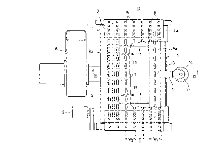
Dispositif d'exposition pour aspirer des matériaux photosensibles de différentes largeurs sur une table d'exposition. Une courroie d'aspiration, entraînée par un moteur, est formée uniformément de nombreux orifices d'aspiration. Une caisse d'aspiration est montée à l'arrière de la courroie d'aspiration avec une plaque de support de courroie formée de nombreux orifices d'aspiration. Deux plaques de réglage sont fixées à l'arrière de la plaque de support de courroie. En réglant la position des plaques de réglage dans le sens de la largeur, les orifices d'aspiration, situés dans les rangées les plus à l'extérieur sur les deux côtés, sont ouverts et fermés. On peut ainsi régler la largeur d'aspiration de la courroie selon la largeur du matériau photosensible.


Abrégé anglais


An exposure device for sucking photosensitive
materials of different widths on an exposure table. A
suction belt, driven by a motor, is formed with a plurality
of suction holes uniformly. On the back of the suction
belt is mounted a suction box with a belt support plate
which is formed with a plurality of suction holes. A pair
of adjusting plates are attached to the belt support plate
on its back. By adjusting the position of the adjusting
plates in a width direction, the suction holes in the
outermost rows at both sides are opened and closed. Thus,
the suction width for the suction belt can be adjusted
according to the width of the photosensitive material.

Revendications

Note : Les revendications sont présentées dans la langue officielle dans laquelle elles ont été soumises.


THE EMBODIMENTS OF THE INVENTION IN WHICH AN EXCLUSIVE
PROPERTY OR PRIVILEGE IS CLAIMED ARE DEFINED AS FOLLOWS.
1. An exposure device, comprising:
a suction belt having a plurality of suction holes
therein arranged in a plurality of rows that extend in a
longitudinal direction of said suction belt;
a suction box;
an exposure table comprising a belt support plate
connected with said suction box, said belt support plate
having a front side for supporting said suction belt, a
plurality of suction holes formed therein in a plurality of
rows that extend in the longitudinal direction of said suction
belt for communication with said suction holes of said suction
belt, and a back side; and
an adjusting plate movably mounted on said back side of
said belt support plate so as to be movable between a closed
position in which some of said suction holes of said belt
support plate are closed and an open position in which said
suction holes of said belt support plate that are closed in
said closed position are open.
2. The exposure device of claim 1, and further comprising a
moving means for moving said adjusting plate between said open
and closed positions in a width direction of said belt support
plate, the width direction being perpendicular to the
longitudinal direction.

3. The exposure device of claim 2, wherein said moving means
comprises a contact element connected with said adjusting
plate, a cam, a motor for driving said cam and a spring
biasing said contact element against said cam.
4. The exposure device of claim 3, and further comprising a
second adjusting plate connected with the first said adjusting
plate, both said adjusting plates extending in said
longitudinal direction and being separated by a plurality of
rows of said suction holes in said belt support plate.
5. The exposure device of claim 1, wherein said adjusting
plate comprises a plurality of holes therein that are aligned
with said suction holes of said belt support plate in said
open position and are misaligned with said suction holes of
said belt support plate in said closed position.
6. The exposure device of claim 5, wherein said adjusting
plate is wider in a direction perpendicular to said
longitudinal direction that the distance in the direction
perpendicular to said longitudinal direction between two rows
of said plurality of suction holes in said belt support plate.
7. The exposure device of claim 1, and further comprising a
blower connected with said suction box for evacuating said
suction box.

Description

Note : Les descriptions sont présentées dans la langue officielle dans laquelle elles ont été soumises.


;~ 2124997
EXPOSURE DEVICE
This invention relates to an exposure device used to
print/expose a negative image on a negative film on a
photosensitive material.
As an exposure device, the one shown in Fig. 5 is
known. In this exposure device, a photosensitive material
P drawn from a roll R is cut to a predetermined size by a
cutter device 30. The photosensitive material Pl, which is
now cut off, is supported on an exposure table 20. A
negative film F is illuminated by a light source 21 to
print/expose the negative image thereon on the
photosensitive material Pl through a printing lens 22.
As shown in Fig. 6, the exposure table 20 in the
exposure device comprises a motor 23, an endless suction
belt 24 driven by the motor 23 and formed with a plurality
of suction holes 2S, a suction box 26 having a support
plate 27 formed with a plurality of suction holes 28, which
are communicable with the suction holes 25 of the suction
belt 24, and a blower 29 for sucking the interior of the
suction box 26. The photosensitive material Pl is sucked
and kept in its position by a suction force applied through
the suction holes 28 and the suction holes 25 until it is
fed to the exposure stage to be printed and exposed.
Furthermore, the photosensitive material Pl after

'_ ~12~9 97;
printed and exposed is fed from the exposure table 20 to a
developing unit (not shown) by the movement of the suction
belt 24.
In such a conventional exposure device, the suction force
is applied through all the suction holes 25 of the suction
belt face 24a regardless of the width of the photosensitive
material P1. If it has a small width, so many suction holes
25 are open that the air is also sucked into the suction box
26 through the suction holes 25.
Thus, the suction force per unit surface area of the
photosensitive material P1 becomes so weak that it is not
sucked enough and gets afloat. This will cause a problem of
fuzziness.
If the suction force is set based on the smallest width
of the photosensitive material P1 to solve this problem, it is
necessary to provide a blower 29 of an extremely large
capacity, resulting another problem of noise. Moreover, the
suction belt 24 has a larger transfer resistance, which will
increase the size of the motor 23 as well as the cost.
It is an object to provide an exposure device which
obviates the aforementioned problems and which makes it
possible to reduce the size of the blower and the motor.
According to the present invention, there is provided an
exposure device, comprising: a suction belt having a
plurality of suction holes therein arranged in a plurality of
rows that extend in a longitudinal direction of said suction
belt; a suction box; an exposure table comprising a belt
'P~

2 ~ 24997
-
support plate connected with said suction box, said belt
support plate having a front side for supporting said suction
belt, a plurality of suction holes formed therein in a
plurality of rows that extend in the longitudinal direction of
said suction belt for communication with said suction holes of
said suction belt, and a back side; and an adjusting plate
movably mounted on said back side of said belt support plate
so as to be movable between a closed position in which some of
said suction holes of said belt support plate are closed and
an open position in which said suction holes of said belt
support plate that are closed in said closed position are
open.
In the exposure device according to the present
invention, since the suction width of the suction belt is
adjustable according to the width of the photosensitive
material, it can be sucked and fed while keeping the adjusted
state.
Thus, even if the suction force is set based on the
photosensitive material having a largest width, the
photosensitive material of a smallest width can be sucked
reliably. In other words, a photosensitive material of any
kind can be sucked stably.
Moreover, since the suction force can be set based on the
photosensitive material having a largest width, a blower and a
motor for feeding the suction belt of a small size may be
used.

2 ~
Other features and objects of the present invention will
become apparent from the following description made with
reference to the accompanying drawings, in which:
r~

2124997
-
embodiment of the exposure table according to the present
invention;
Fig. 2 is a sectional view taken along II - II of
Fig. 1;
Fig. 3 is a sectional view taken along III - III of
Fig. l;
Fig. 4 is a sectional view showing how the suction
width is adjusted;
Fig. 5 is a schematic view of the exposure device;
and
Fig. 6 is a partially cutaway perspective view of a
prior art exposure table.
An exposure table 1 comprises an endless suction belt
3 driven by a motor 2, and a suction box 4 for supporting a
suction belt 3a at its carrier side.
The suction belt 3 is formed with a plurality of
suction holes 5 spaced apart predetermined intervals with
one another in its feed direction. They are provided in a
plurality of rows in a width direction of the suction belt
3. In the embodiment, the suction holes 5 are provided in
seven rows.
The suction box 4 has a belt support plate 6 for
supporting the suction belt 3a at the carrier side. The
belt support plate 6 is formed with a plurality of suction
holes 7 spaced apart predetermined intervals with one

2124997
another in a feed direction. They are provided in a
plurality of rows in a width direction of the suction belt
3. The interval between the rows of the suction holes 7 in
the belt support plate 6 is the same as that of the suction
holes 5 in the suction belt 3 so that the rows of the
suction holes 5 and 7 are aligned with each other.
Further, the suction holes 7 are elongated in a feed
direction of the suction belt 3. Thus, even while the
suction belt 3 is being fed, any of the plurality of
suction holes 5 formed in the suction belt 3 will
communicate with one of the suction holes 7.
A blower 8 is connected to the suction box 4 to suck
the interior of the suction box 4.
A pair of adjusting plate 9a and 9b in the form of
strips are attached to both sides of the belt support plate
6 from its back. Their width Wl is larger than the
interval W2 between the adjacent rows of the suction holes
7.
At the center of the adjusting plates 9a and 9b are
formed a plurality of elongated holes 10 spaced apart
predetermined intervals with one another in their
longitudinal direction. By moving the adjusting plates 9a
and 9b in a width direction, the elongated holes 10 will be
aligned with the suction holes 7.
The adjusting plates 9a and 9b are coupled to each

2124997
,.",
other by a link 11. To the adjusting plate 9a is mounted a
contact element 12 which slidably extends through a side
plate of the suction box 4 and is kept into contact with a
cam 14 driven by a motor 13.
Springs 15 are coupled to the other adjusting plate
9b. The contact element 12 is urged against the cam 14 by
the bias of the spring 15.
Fig. 3 shows a state in which the elongated holes 10
formed in the adjusting plates 9a and 9b and are not in
alignment with the suction holes 7 in the belt support
plate 6. In this state, the suction holes 7 in the
outermost two rows on both sides are closed by the
adjusting plates 9a and 9b.
Therefore, if the blower 8 is activated, the suction
force will be applied to the suction holes 7 in the central
three rows, and thus only to the suction holes 5 which
communicate with these suction holes 7. A1 in Fig. 3 shows
the suction width when the adjusting plates 9a and 9b close
the suction holes 7 in the outermost two rows at both
s ldes .
From this state shown in Fig. 3, the cam 14 is driven
by the motor 13 to move the adjusting plates 9a and 9b in a
width direction of the belt support plate 6. The motor 13
is stopped as soon as the elongated holes 10 of the
adjusting plates 9a and 9b have come into alignment with

2124997
',~
the suction holes 7 of the belt support plate 6. As shown
in Fig. 4, all the suction holes 7 are now open, so that
the suction force is applied through the suction holes 5
communicating with the suction holes 7. A2 shows the
suction width in this state.
By moving the adjusting plates 9a and 9b widthwise,
the suction width acting on the suction belt 3a at the
carrier side can be adjusted in two steps. Thus, by
adjusting the suction width according to the width of the
photosensitive material P1 fed by the suction belt 3, the
photosensitive material P1 of different widths can be
sucked stably.

Dessin représentatif
Une figure unique qui représente un dessin illustrant l'invention.
États administratifs

2024-08-01 : Dans le cadre de la transition vers les Brevets de nouvelle génération (BNG), la base de données sur les brevets canadiens (BDBC) contient désormais un Historique d'événement plus détaillé, qui reproduit le Journal des événements de notre nouvelle solution interne.

Veuillez noter que les événements débutant par « Inactive : » se réfèrent à des événements qui ne sont plus utilisés dans notre nouvelle solution interne.

Pour une meilleure compréhension de l'état de la demande ou brevet qui figure sur cette page, la rubrique Mise en garde , et les descriptions de Brevet , Historique d'événement , Taxes périodiques et Historique des paiements devraient être consultées.

Historique d'événement

Description Date
Inactive : CIB de MCD 2006-03-11
Le délai pour l'annulation est expiré 2002-06-03
Lettre envoyée 2001-06-04
Accordé par délivrance 1999-03-09
Inactive : Taxe finale reçue 1998-11-17
Préoctroi 1998-11-17
Un avis d'acceptation est envoyé 1998-10-01
Lettre envoyée 1998-10-01
Inactive : Dem. traitée sur TS dès date d'ent. journal 1998-09-21
Inactive : Renseign. sur l'état - Complets dès date d'ent. journ. 1998-09-21
Inactive : CIB en 1re position 1998-08-10
Inactive : CIB enlevée 1998-08-10
Inactive : CIB attribuée 1998-08-10
Inactive : Approuvée aux fins d'acceptation (AFA) 1998-08-10
Exigences pour une requête d'examen - jugée conforme 1996-02-13
Toutes les exigences pour l'examen - jugée conforme 1996-02-13
Demande publiée (accessible au public) 1994-12-09

Historique d'abandonnement

Il n'y a pas d'historique d'abandonnement

Taxes périodiques

Le dernier paiement a été reçu le 1998-03-20

Avis : Si le paiement en totalité n'a pas été reçu au plus tard à la date indiquée, une taxe supplémentaire peut être imposée, soit une des taxes suivantes :

  • taxe de rétablissement ;
  • taxe pour paiement en souffrance ; ou
  • taxe additionnelle pour le renversement d'une péremption réputée.

Les taxes sur les brevets sont ajustées au 1er janvier de chaque année. Les montants ci-dessus sont les montants actuels s'ils sont reçus au plus tard le 31 décembre de l'année en cours.
Veuillez vous référer à la page web des taxes sur les brevets de l'OPIC pour voir tous les montants actuels des taxes.

Historique des taxes

Type de taxes Anniversaire Échéance Date payée
TM (demande, 4e anniv.) - générale 04 1998-06-02 1998-03-20
Taxe finale - générale 1998-11-17
TM (brevet, 5e anniv.) - générale 1999-06-02 1999-04-29
TM (brevet, 6e anniv.) - générale 2000-06-02 2000-05-18
Titulaires au dossier

Les titulaires actuels et antérieures au dossier sont affichés en ordre alphabétique.

Titulaires actuels au dossier
NORITSU KOKI CO., LTD.
Titulaires antérieures au dossier
MASAAKI TSUJI
Les propriétaires antérieurs qui ne figurent pas dans la liste des « Propriétaires au dossier » apparaîtront dans d'autres documents au dossier.
Documents

Pour visionner les fichiers sélectionnés, entrer le code reCAPTCHA :


Pour visualiser une image, cliquer sur un lien dans la colonne description du document. Pour télécharger l'image (les images), cliquer l'une ou plusieurs cases à cocher dans la première colonne et ensuite cliquer sur le bouton "Télécharger sélection en format PDF (archive Zip)" ou le bouton "Télécharger sélection (en un fichier PDF fusionné)".

Liste des documents de brevet publiés et non publiés sur la BDBC .

Si vous avez des difficultés à accéder au contenu, veuillez communiquer avec le Centre de services à la clientèle au 1-866-997-1936, ou envoyer un courriel au Centre de service à la clientèle de l'OPIC.


Description du
Document 
Date
(aaaa-mm-jj) 
Nombre de pages   Taille de l'image (Ko) 
Abrégé 1995-04-13 1 107
Dessins 1995-04-13 5 249
Revendications 1995-04-13 1 52
Description 1995-04-13 7 423
Description 1998-07-14 8 210
Revendications 1998-07-14 2 67
Dessins 1998-07-14 5 75
Dessin représentatif 1999-03-01 1 11
Avis du commissaire - Demande jugée acceptable 1998-09-30 1 163
Avis concernant la taxe de maintien 2001-07-02 1 178
Correspondance 1998-11-16 1 39
Paiement de taxe périodique 1997-02-27 1 54
Paiement de taxe périodique 1995-02-28 1 59
Correspondance de la poursuite 1994-06-01 8 244
Courtoisie - Lettre du bureau 1996-03-05 1 53
Correspondance reliée aux formalités 1996-02-12 1 45
Correspondance de la poursuite 1996-05-08 1 50
Correspondance de la poursuite 1998-06-02 3 90
Demande de l'examinateur 1997-12-03 2 71