Note: Descriptions are shown in the official language in which they were submitted.
21253S5
...
HORIZONTAL DRILLING METHOD ~OR HYDROCARBON RECOVER~
BACKGROUND OF THE INVENTION
1. Field of the Invention
The present invention relates to methods for
hydrocarbon recovery, and more particularly pertains to a
method for recovering subterranean oil and gas.
2. Description of the Prior Art
Various drilling methods have been practiced for
the recovery of subterranean oil and gas. Initially, for
relatively new fields, it is frequently necessary merely to
drill a vertical well into a producing reservoir or
~ formation. As such easily producible fields are becoming
-' increasingly depleted, there has been great interest in
increasing production from depleted or semi-depleted fields,
and from fields where the least expensive methods of
production have been found inadequate. U.S. Patent No.
4,463,988 which issued to Bouck et al. on August 7, 1984
discloses a method for recovering hydrocarbons from tar sand
deposits in which steam is injected into bore holes
extending laterally from a vertical shaft. The steam causes
the tar sands to become viscous and flow by gravity into the
bore holes. U.S. Patent No. 4,607,888 which issued to Trent
et al. on August 26, 1986 discloses a method for recovering
hydrocarbons in which water occurring in the hydrocarbon
formation is used to wash fluid hydrocarbons from a porous
2125355
.
formation by inject~ng the water into bore holes extending
from an underground tunnel or shaft. U.S. Patent No .
4,611,855 which issued to Richards on September 16, 1986
discloses a method for collecting subterranean methane in
which lateral bore holes drilled at axially spaced locations
along a vertical shaft collect and conduct methane to the
shaft for extraction. U.S. Patent No. 4,753,485 which
issued to Goodhart on June 28, 1988 discloses a method for
extracting oil in which a plurality of deviated wells extend
upwardly and outwardly from a vertical shaft. Steam
injected into the deviated wells causes oil to drain through
the deviated wells into the vertical shaft for collection.
U.S. Patent No . 5,082,054 which issued to Kiamanesh on
January 21, 1992 discloses a method for oil extraction in
which microwave irradiation is employed in conjunction with
a plurality of horizontal canals connected to a central
; vertical well.
SUMMARY OF THE INVENTION
The instant application discloses a method for
recovering hydrocarbons from underground reservoirs and
formations in which fluids are produced in horizontal wells,
but instead of the fluids being routed conventionally up the
wellbore to the surface in the horizontal wellbore, they are
- instead routed into an interconnecting vertical wellbore or
one that penetrates the producing formation in close
2125355
.. ..
proximity of the horizontal wellbore. Thereafter, they are
then produced to the surface either by flowing utilizing
reservoir energy or by pumping utilizing artificial lift
equipment. The process is applicable for producing fluids
which may be present in a hydrocarbon reservoir including
crude oil, associated solution gas, formation water, water
which may have been injected into the formation, natural gas
and other gases, and natural gas liquids. The method of the
instant invention includes the steps of drilling one or more
horizontal wells such that the horizontal well intersects or
terminates in close proximity of an existing or newly
drilled vertical wellbore or drilling a vertical well
specifically to intersect or penetrate the producing
formation in close proximity to an existing or newly drilled
horizontal wellbore, routing fluid produced in the one or
more horizontal wells to the vertical wellbore, and
producing the recovered fluids to the surface in the
vertical wellbore utilizing reservoir energy or artificial
lift equipment.
These and various other advantages and features of
novelty which characterize the invention are pointed out
with particularity in the claims annexed hereto and forming
a part hereof. ~owever, for a better understanding of the
invention, its advantages, and the objects obtained by its
use, reference should be made to the drawings which form a
further part hereof, and to the accompanying descriptive
212~355
~,. ..
matter, in which there is illustrated and described pre-
ferred embodiments of the invention.
.
BRIEF DESCRIPTION OF THE DRAWINGS
Figure 1 is a diagrammatic cross-sectional view
taken along a vertical plane and illustrating an example
well system for producing hydrocarbons according to the
method of the present invention.
Figure 2 is a diagrammatic cross-sectional view
taken along a horizontal plane and further illustrating the
example well system of Figure 1.
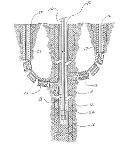
DETAILED DESCRIPTION OF THE PREFERRED EMBODIMENT(S)
Referring now to the drawings, wherein like refer-
ence numerals designate corresponding structure throughout
the views, and referring in particular to Figures 1 and 2,
an improved method for hydrocarbon recovery 10 according to
an example embodiment of the invention includes a vertical
; wellbore 12 conventionally provided with a porous casing 12.
The wellbore 14 may be plugged at a desired depth by a plug
14, dependent upon the location of pay zones within the
reservoir or formation. A plurality of horizontal wells 16,
20, 30, and 34 include respective non-porous sections of
casings 17, 21, 31, and 35, and porous sections of casing or
open hole 18, 22, 32, and 36 each intersecting or
terminating in close proximity to the vertical wellbore 10,
2125355
at the same or different depths. Within the sco~e of this
description, the term "horizontal well" means a well which
includes a substantially horizontal portion, such as
horizontal porous or open hole portion 18 of well 16, or the
horizontal porous open hole portion 22 of well 20. Such
horizontal wells are drilled from the surface utilizing
conventional equipment such that the horizontal wells
include an initially vertical portion which curves and
becomes a horizontal portion of the wellbore. In accordance
with conventional methods, horizontal wells have been
previously employed by collecting fluids in the horizontal
portion of the well and by routing collected fluids to the
surface via the vertical portion of the horizontal well,
utilizing reservoir energy or artificial lifting equipment.
In accordance with the instant invention, fluids collected
in the horizontal wells drain by gravity or reservoir
pressure through the porous section of casing or open hole
into the vertical wellbore 10, as indicated by arrows A and
B, which advantageously extends to a depth below both the
pay zone and the intersections with the horizontal wells,
forming a sump for the collected fluids. A pump 24, such as
an electric submersible pump, may be provided in the sump
for producing collected fluids to the surface through
conduit 26.
The method of the present invention may be
employed in connection with entirely new well systems, or to
2125355
~.
improve the production of an existing instal~ation by
drilling a vertical wellbore to intersect one or more
existing horizontal wells, or by drilling one or more
horizontal wells to intersect or terminate in close
proximity to an existing vertical wellbore.
In the inventive system, fluid production from a
hydrocarbon formation or reservoir enters a horizontal
wellbore through perforations or openings in the pipe and
mi~rates through the horizontal portion of the horizontal
wellbore into an interconnecting vertical wellbore or
vertical wellbore in close proximity at the far end of the
; horizontal wellbore. One or more horizontal wells are
drilled to intersect an existing vertical wellbore or a
vertical wellbore drilled specifically for this purpose.
Production of fluids from a hydrocarbon reservoir utilizing
this combination of wells involves routing produced fluids
through the opposite end of the horizontal wellbore as
compared to the conventional method in which the produced
fluids enter the horizontal portion of the wellbore and are
routed up the tubular pipe to the surface through the
vertical end of the conventional horizontal well. Producing
fluids from a hydrocarbon reservoir with the inventive
system is technically, practically and mechanically more
efficient than producing the same fluids through either a
longer, curved conventional horizontal wellbore or through a
single conventional vertical wellbore. Accordingly, the
2125355
..
inventive method achieves many advantag~s, some of which are
described in detail below.
Less energy is required to lift the produced
fluids to the surface in the inventive system in the shorter
interconnecting vertical well than that which would be
required to lift the same volume through the longer, curved
horizontal and vertical portions of the wellbore due to
lower friction of the fluids inside the tubular production
pipes. Over the life of a reservoir or field, the energy
saved with the inventive system would be significant. In
the later life of a reservoir or field, when formation
pressures have declined to the point where insufficient
pressure energy remains to cause the fluids to flow or to be
easily lifted, there would be a significant saving in
operating costs associated with the inventive system as
compared to the costs to produce conventional separate
vertical or individual horizontal wells. In a the inventive
system, production rates would be higher from the same
formation than those for conventional wells because of the
more efficient use of reservoir energy. Reservoir pressure
or energy required to drive the produced fluids from the
reservoir into the horizontal portion of the horizontal well
and out of the lower end into the vertical wellbore or in
close proximity to the vertical wellbore would be much lower
than that required to drive or lift the fluids up the
wellbore of the horizontal well.
21253~5
Capital costs associated with the inventive syste~
would be considerably lower as a result of the following:
(a) More than one horizontal well can be
interconnected to the same vertical wellbore. For instance,
should there be four horizontal wells interconnected to one
vertical wellbore, only one instead of four sets of downhole
production equipment and only one set of surface facilities
would be needed.
(b) The flowline pipe required to transport
produced fluids to a central storage facility is reduced for
a multi-well of the inventive system as compared to a
conventional system resulting in a saving in capital costs.
Surface disturbances associated with the pipelines in a
multi-well formed pursuant to the inventive system are
substantially reduced, since fewer producing wells are
required.
(c) By strategic planning of the surface locations
for a multi-well field utilizing the inventive concept, few
surface locations are required since it is possible to drill
several wells from one surface location, thus greatly
reducing capital costs for lease construction and ongoing
lease rental costs. By reducing surface disturbance, there
is less of an impact on the environment.
(d) For reservoirs containing low gravity and
highly viscous crude oil, utilizing the inventive system has
a significant positive advantage over conventional systems
2125355
(. . .
since the reservoir energy ~quired to drive the fluids into
the wellbore is reduced. In the inventive system, the back
pressure against which the reservoir must produce can be
virtually eliminated through the utilization of artificial
lift equipment resulting in increased production. It is
possible to draw down the level of the production fluid in
the vertical wellbore by means of pumping or artificial lift
equipment so that the level of the fluids remains below the
producing formation in the vertical wellbore of the
inventive system. Production capability of the reservoir is
thus greater, especially in the latter stages of those
fields where reservoir pressure has declined to the extent
that insufficient energy remains to lift the produced fluids
to the surface. Under conventional production techniques
using single vertical wells, the ability of the reservoir to
drive fluids into a wellbore is much lower than that for the
inventive system because of the much lower area contacted by
the vertical wellbore. Well servicing, lifting and
operating costs are higher for conventional horizontal wells
because of the difficulty and expense associated with
lifting the production from within and/or below the curved
portion of the horizontal wellbore. Reducing or eliminating
these costs through the use of the inventive system would
amount to a very significant saving over the life of a
producing field. When operating costs exceed revenue, it is
necessary to abandon producing wells in a field which
~125355
( .
results in a larger portion of the hydrocarbons remaining
unrecovered in the formation under conventional production
systems as compared to the inventive system. Capital costs
for drilling conventional horizontal wells are higher since
larger diameter borings are required to accommodate larger
tubular goods associated with the conventional horizontal
wells being produced through the vertical portion of the
horizontal well. Also, capital costs for flowlines and
production equipment can be reduced or eliminated through
utilization off the inventive system.
(e) With the inventive system, the horizontal well
or wells interconnected or terminating in close proximity to
the central vertical well can be utilized as observation
wells to monitor surface and downhole pressures on a
continuous or regular basis, thus allowing for better
management of the reservoir with resulting improved
reservoir performance.
(f~ In the inventive system, the lower or face end
of the horizontal wellbore can be isolated from the
interconnecting vertical wellbore in order to perform
workovers or stimulations on the formation without
disrupting production from other wells producing into the
same central vertical wellbore.
(g) In the inventive system, utilizing one central
vertical wellbore to collect production from several
horizontal wells, the central vertical well can be sized to
21253~
~ (
produce greater,volumes than is posslble utilizing
conventional vertical or horizontal wells. By utilizing
larger diameter tubular goods, in the vertical wellbore,
downhole production equipment can be sized to produce the
larger volumes associated with the inventive system. The
ability to utilize artificial lift equipment capable of
larger volumes such as electric driven submersible pumps to
produce the vertical well in the inventive system has
economic benefits over conventional methods of production.
By drilling the central vertical well sufficiently deep such
that a sump is created below the point of intersection of
the horizontal wellbore with the vertical wellbore, produced
fluids could be lifted or pumped by means of high volume
artificial lift equipment which could result in higher
production volumes than is possible with conventional wells.
Production can be more continuous and stable than that
possible utilizing a conventional system in the latter
stages in the life of a field.
(h) Should there be more than one pay zone in the
area surrounding the central vertical wellbore, and should
there be a need to segregate production from each of two or
more pay zones, it may be more economical to use a separate
multi-well system pursuant to the invention for each pay
zone or, if desirable, the central vertical well can be
dually completed utilizing downhole packers and more than
one production tubing string.
1 1
2125355
~.
In situations where a conventional horizontal
producing well exists, an intersecting vertical well can be
drilled to create a two-well system or a multi-well system
by extending existing horizontal wellbores such that they
intersect or terminate in close proximity to the vertical
wellbore, pursuant to the method of the present invention.
The direction of the produced fluids would be reversed in
the existing horizontal wellbore and be routed into the
interconnecting vertical wellbore and to the surface as in
the inventive system explained herein. It is to
be understood, however, that even though numerous
characteristics and advantages of the present invention have
been set forth in the foregoing description, together with
details of the structure and function of the invention, the
disclosure is illustrative only, and changes may be made in
detail, especially in matters of shape, size and arrangement
of parts within the principles of the invention to the full
extent indicated by the broad general meaning of the terms
in which the appended claims are expressed.