Note: Descriptions are shown in the official language in which they were submitted.
,,
4(60CAN
METHOD OF COMPRESSING DATA IN AN ULTRASONIC
PIPE INSPECTION PROBE
The invention relates to a method of compressing
data obtained from ultrasonic measurements made by an ultra-
sonic pipe inspection probe which detects corrosion or other
abnormalities in a pipe wall. The data are derived from
ultrasonic propagation time measurements which are obtained
by ultrasonic transducers combined in a module. The module
or modules are disposed on predetermined circumferential
areas of an ultrasonic pipe inspection probe with which they
slide along the inner surface of a pipe to be checked. The
ultrasonic transducers emit an ultrasonic pulse with a
repetition frequency adjusted to the probe speed and receive
the echo returned from the inner and outer surfaces of the
pipe. By determining the travel time difference and taking
into consideration the sound speed, the remaining thickness
of the pipe can be determined over its whole surface.
Because of the signalfstatics ratio preferably the first
received echoes are utilized.
The data derived from the measurements are
recorded in a data storage during the travel of the
ultrasonic inspection probe. However, the amount of data is
very large. 4Jithout data compression the limits of the data
storage are rapidly reached which substantially limits the
travel distance of the ultrasonic inspection probe.
Normally, however, .it can be assumed that the
walls of a pipeline are essentially sound, that is, in goad
shape, over long distances. In those areas of course not
1
~\
Zl~a~i~i
all the measurements need to be stored but the tolerable
measurement values can be replaced by a representative
value. Upon retrieval of the data from the data storage
after completion of the travel through the pipeline, the
~ condition of the pipeline should be represented without any
gaps.
DE 3638936 discloses a method wherein the data are
compressed in such a way that measurement values deviating
from a previous measurement value within a predetermined
range (tolerance band) are only counted and recorded and
stored by numbers. However, with the predetermined range
this method does not or does not sufficiently reduce
recording requirements when the wall thickness changes or
the sensor mounting structure is worn, since, in those
cases, the measurement values are outside the predetermined
range. Furthermore, with this method the predetermined
range may fail into a measurement value range which is
important for corrosion determination whereby the quality of
the quantitative corrosion determination is reduced.
Known methods of data compression are described
and explained in DATACOMl9l, pages 88 ff. The most suitable
method is, for example, the Huffmann-coding (see page 94,
columns 2 and 3 and page 96, columns 1 and 2>. However,
these methods do not take into consideration the physical
laws of ultrasonics. Consequently no great savings are
achieved therewith.
Ultrasonic data are recorded, for example, in a
12-bit data format. The first stage of the compression
includes a data reduction. From the 12-bit data format the
information is selected which is needed for later corrosion
determination. For this a 7-bit data format is sufficient
which is a subquantity of the 12-bit data format. This data
format covers a defined value range with a predetermined
resolution.
Each set of data comprising 64 advancement and
wall thickness values entered into a compression computer is
taken as a data set and compressed. The compression is
2
~l~~~i6~
based on the assumption that pipelines are free of corrosion
over long distances and measurement values taken do not
i
distinguish or are within a narrow tolerance band. This
tolerance band is generated by arranging a window of
predetermined width around a previously determined reference
value. lJith the tolerance band the roughness of the wall
and irregularities in the manufacture of the pipe are
suppressed. By means of this tolerance and compression
window the data are recorded with two different resolution
ranges: a fine resolution for the corrosion areas and a
rough resolution in the areas of normal wall thickness or
nominal advancement.
The principle of the data compression method
resides in the representation of multiple consecutive data,
which are within the tolerance band, by means of a
multiplier. The 7-bit data representation permits
assignment of a special meaning to the eighth bit of a data
word. The eighth bit is util ized as a prefix bit in order
to be able to change the interpretation of the data word.
The first seven bits may then contain a multiplier rather
than a measurement value whereby it contains the number of
measurement values which are within the predetermined
tolerance range which are formed around the preassigned
reference value. Maximally this may be 128 such values
which corresponds to a binary representation of 7 bits. If
a measurement value is outside the window, its value is
fully recorded. The prefix bit is then not utilized. The
multiplier count starts at 80H wherein 80H corresponds to a
multiplier of 1. In the most advantageous case, when all
measurement values are within the tolerance bands
consequently only one byte with the value of 255 t=FFH) is
recorded. It is the most disadvantageous case when all
measurement values are outside the tolerance bands or one or
more values outside the tolerance band are always followed
bY a value within the tolerance band. In both these cases,
128 bytes have to be recorded.
3
~~~5 i~
It is the object of the present invention to
increase the data compression in the data storage of an
ultrasonic pipe inspection probe so that it can pass through
long stretches of pipelines without limitations and
efficiently while the rough environmental conditions are
particularly taken into consideration for data storage.
This object is solved in accordance with the
invention by the features given in the characterizing clause
of claim 1. The subclaims 2 to 8 define further
advantageous method steps for optimal compression of
decompressible data.
The measurement values for the advancement depend
on the distance of the transducer carrier from the inner
pipe wall, on the wear of the transducer carrier during
probe advancement and on the condition of the inner wall of
the pipeline stretch to be measured. Generally, for each
transducer the base setting and the wear of the transducer
carrier are different. Therefore a particular advancement
reference value is assigned to each transducer. The
reference value is formed by averaging which is maintained
over the whole probe travel so that, with wear, the
reference values are automatically continually adjusted.
Far measurement of the wall thickness a single
reference value is utilized for all transducers since all
transducers normally are measuring walls of the same thick
ness. The wall thickness reference value is formed by the
same continuous averaging. The tolerance band is defined by
a reference value and a window which is symmetrically
disposed around the reference value in predefined units.
An extended sequence of skips is represented by a
multiplier: Then as prefix a data word is utilized to which
a value is assigned (1> which makes no sense as a
measurement value in connection with the measurements taken.
For example, the measurement value "one" corresponds to a
wall thickness of 0.2 mm or an advancement value of 0.34 mm.
Such values cannot be measured for physical reasons.
4
Z~.w~~~~
If the compression of several consecutive data
sets represents a sequence with optimal compression (=FFH)
several data sets can be combined via one multiplier by
means of a prefix byte which directly follows the
synchronization bytes.
The compression factor is determined essentially
by the data structure, which is much dependent on the
measurement parameters and therefore is not predictable. In
order to be able to better compress the data of various
sensors which are in a sequence autside the tolerance band
but which cannot be changed at that point the compression
can be performed in two alternative stages. Stage 1
corresponds to the method described. In the second stage
the respective previous measurement values of the same
transducer are utilized as reference values, not the base
reference values as utilized in the first stage.
Measurement values within the tolerance band are represented
by the reference value. If subsequent corresponding values
differ they are fully (or by their difference) recorded; the
same measurement values are described by a single
multiplier. If differences are recorded, two consecutive
identical measurement value differences can be defined by a
single byte.
At the end of stage two it is determined on the
basis of the achieved compression factor by which method the
compressed data are recorded. The compressed data set is
then provided with a corresponding marker. Since the method
according to stage two requires a greater data storage
security, this method is utilized only if data compression
is substantially improved and with storage means having high
data reliability.
At the end of a test run the ultrasonic data are
evaluated. For this the data need~to be decompressed. A
multiplier is then replaced by the corresponding number of
the respective reference values.
The gathering of the reference values is of
particular importance. If possible, a situation has to be
5
21~5~6
avoided wherein the tolerance band extends into the
measurement value range of the corrosion areas since
otherwise the quantitative determination of the corrosion
areas will have insufficient resolution. The reference
value for the wall thickness is found by arithmetic
averaging of a defined number of data sets; it is therefore
adjusted continuously to different wall thicknesses. Echo
skips (measurement value 0) and range transgressions
(measurement value 127) are disregarded for averaging. In
order to avoid detrimental influences of far off-base
measurement values on the averaging procedure, in the first
stage only those values are utilized for averaging which are
disposed within the predetermined window. If more values
are disposed outside the window than within (for example,
after a change of wall thickness) all values of the data set
are utilized for averaging.
By the arrangement of the transducers which are
displaced in Tongitudinal direction on the sensor carrier, a
stepped function of the reference value can be obtained if
the wall thickness changes are large relative to the
tolerance band width. In order to avoid the need to accept
in this area corrosion measurements with insufficient
resolution the tolerance band is reduced for a short period
if a change of wall thickness is recognized. Therefore the
compression method must be designed to be able to tolerate
errors.
The quantitative determination of interior
corrosion on the basis of the advancement data is obtained
by a relative measurement. Interior corrosion is always
indicated by an increase in the wall distance measurement
value (see Fig. 1>. For the quantitative calculation two
wall distance measurement values are subtracted. One
measurement value corresponds to the wall distance value at
the corrosion location. The second measurement value
corresponds to the wall distance value in a defect-free
pipe. For a defect-free pipe the wall distance value is
given by the reference value. Consequently, the measurement
6
~,~~'~J~1~
values obtained at corrosion locations and during sensor
carrier upliftings must be filtered out for the deter-
mination of the reference values for the wall distance.
This is achieved by disregarding measurement values which
are high relative to the instant reference value (as a
result of corrosion or sensor carrier uplifts>.
At the beginning of a test run the reference
values are generated by averaging a predetermined number of
data sets. The subsequent reference value calculations are
Performed during the data gathering and data compression
procedures.
The data loss of particular information units suf-
fered with each compression procedure results in
substantially greater data losses or greater data
misrepresentation after the decompression. This is
particularly true for the data losses of reference values.
In order to achieve the greatest possible security for the
data storage the reference values are stored redundantly
several times. At the beginning of a data block the
2p reference values of the previous run are stared in two
different data sets. They are then valid for the whole data
block. Since the wail thickness reference value can change
frequently the particular instant wall reference value is
attached preferably to each tenth data set.
Because of the physical and technical limiting
conditions in the ultrasound measurement of pipelines, there
are for the data compression the following requirements:
-- as great a compression factor as possible;
-- resolution of the corrosion location
measurement:
0.2 mm for a wall thickness up to 25 mm,
0.4 mm for wall thicknesses between 25
and 50 mm for a preliminary run,
-- an algorithm which allows for rapid and error
free synchronization even with non-restitutable flawed band
locations (error tolerance).
7
An embodiment of the invention is schematically
shown in the drawings and will be described. First,
however, an ultrasound measuring procedure is described for
explanation and the flood of measurement values obtained
during a test run is pointed out. The utility of data
compression is apparent therefrom.
After completion of a probe passage the data are
evaluated with the aid of a computer. For this purpose the
data are decompressed. The pipe is straightened out in a
plane herefor whereby each sensor appears to move in a
straight line in the direction of the pipe axis. The
measurement values obtained at the various points are
indicated by different color representations (in Fig. 3 gray
contrasts>. In this manner a three-dimensional
representation (C-scan) is achieved. For the quantitative
determination of corrosion dimensions particular transducer
data can be given in an x-y representation (B-scan).
It is shown in:
Figure 1 the principle of ultrasonic (US)
measuring and recording of the measuring process.
Figure 2 an example of a compression of
ultrasonic data derived from a 16-transducer probe.
Figure 3 the B- and C- scan representation
of the wall distance data at a corrosion location with
subsequent circumferential welding seam. The B-scan shows
the wall distance reference value, the tolerance band and
the measurement values required for the determination of the
corrosion geometries.
Far measuring the remaining wall thickness 1 of
corroded pipelines the ultrasound system is employed in
accordance with the principle of the ultrasound--travel
time--procedure. The ultrasound impulse 2 emitted from a
transducer 3 reaches the pipe wail 4 at a right angle. Far
each ultrasound impulse two travel times are determined,
that is:
travel time between sending impulse and sound wall
entrance impulse,
8
~l~~:i~~
travel time between sound wall entrance impulse
and a first back wall echo or travel time in the back wall
echo sequence. '
From the travel time difference between the front
wall and the back wall echoes the remaining wall thickness
is determined. Fig. 1 shows the measuring principle. From
the distance 7 between transducer 3 and the adjacent pipe
wall, some identification of the kind of corrosion can be
made. With inside corrosion 5 the distance 7 becomes
larger; if it does not change while the wall thickness 8
becomes smaller the defective area 6 is on the outside, that
is, there is outside corrosion 6.
The inside corrosion 5 can correspondingly be
determined by a change of the signal travel distance to the
pipe wall and the wall thickness. The determination of the
inside corrosion 5 via the signal travel distance is a
relative measurement procedure whereas the wall thickness
measurement is an absolute measurement procedure.
For physical reasons the impulse amplitude of the
front wall echo is always greater than the impulse amplitude
of the back wall echo. In highly corroded areas the ultra
sound impulse is weakened and scattered so that often only
the wall distance measurement can be performed.
In order to fully irradiate the pipe wall over its
whole surface a number of transducers have to be provided
circumferentially next to one another which corresponds to
the surface area to be measured and all have to be energized
one after the other for supplying the desired information.
If, in the ultrasound signal generation, ~a repetition
frequency that fits the probe travel speed is utilized, it
is possible to achieve a gap-free examination also in
longitudinal direction. Such an azimuthal and longitudinal
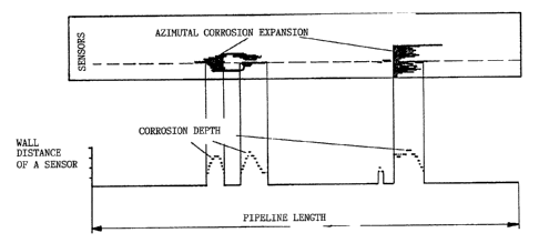
recording of the wall conditions is shown in Fig. 3. The
upper shade-like representation shows qualitatively the
azimuthai condition of the pipe wall over the pipe length.
The lower representation gives quantitatively the wall
thickness along the sensor track indicated by the arrow.
9
Values obtained by the coordination of the azimuthal or
surface representation from the signals of the azimuthally
distributed transducers and the signal representation from a
particular transducer are indicated by dash lines. In a
computer printout a quantification of the corrosion depth in
the pipe wall can be achieved for azimuthal recording also
by way of color tones.
The recorded measurement values have to be
retained for later evaluation. This requires a storage
1p memory with large storage capacity as can be seen from the
estimation given below:
A pipe of 200 km length is to be checked out; it
is assumed to have a diameter requiring 512 transducers
evenly distributed over the circumference. If the probe is
traveling at a speed of 1 m/sec and the ultrasonic
transducers are energized with a frequency of 400 Hz the
resulting data amount is:
N - 512 x 2 x 400 x 200,000
Byte Number of Front and Repeat fre- Travel time at
transducers rear wall quency, echo travel speed
of 1 m/sec
- 81.9 GByte
This amount of data cannot be directly recorded
with presently available data storage systems given the
probe body volume. However, as mentioned earlier, a
pipeline will normally be sound over long distances and will
not be corroded. It is therefore possible to utilize a data
compression which greatly reduces the amount of information
to be stored.
The ultrasonic measuring system is divided into .
modules with preferably 16, 32 or 64 transducers. Depending
on the pipeline diameter up to 8 such modules are utilized.
The individual transducers of a module are energized
sequentially with a repetition frequency of up to 400 Hz.
The data of a transducer module are supplied to a
compression computer where they are compressed and, tacked
with a particular characterization, check sum and synchron
~:~~5~~
marks, transferred to a register computer. The register
computer combines the data of different compression
computers to blocks of about 1.8 (lByte length and deposits
them in a predetermined format in a tape storage.
For a 64-transducer ultrasonic module a data set
contains 64 wall distance and 64 wall thickness values.
These data are taken by the compression computer and stored
sequentially corresponding to the transducer number.
V1 j wall distance 1. transducer
lJl j wall thickness 1. transducer
V2 j wall distance 2. transducer
lJ2 j wall thickness 2. transducer
t
V64 j wall distance 64. transducer
I~64 ,~ wall thickness 64. transducer
j - set number, counting from the beginning of data
recording.
Fig. 2 shows an example of the compression proce
dure. The data set given consists of 16 value pairs. The
wall distance window comprises 2 units, the wall thickness
window comprises 3 units.
The savings for.a data set with 2 x z values which
can be achieved with this compression procedure can be
described by the following formulas
2
Savings E = ~ AK x (k-1)
k=1
AK = number of groups with k values within the tolerance
band
This formula shows that the savings are greatest
when k is very large. lJhen k=1 (Sequence: value outside,
value within, value outside) no savings can be achieved.
The maximum savings for a data set are 127.
The compression rate KG for an individual data set
with 2 x z values is calculated as
11
.
~1~
KG = 2 x z / (2 x z - E) .
It is for the most advantageous case: KG = 2 x z.
For the example in Fig. 2 the savings are:
E = 1 x (9-1> + 1 x (11-1> + 1 x (1-1> = 18
The compression rate is:
KG = 32/14 = 2.28.
In order to achieve the greatest possible savings
physical relationships resulting from the ultrasonic
technology and from the design of the transducer carrier are
utilized in order to prepare the data optimally for the
compression:
-- In the neighborhood of weld seams the
transducer carrier is raised slightly; this results in an
increase of the distance but does not change the wall
thickness values. By reorganization of the data wherein
first the distance data and then the wall thickness data are
compressed the savings E can be increased.
-- In the areas of pipe installations and with
soiling or failures of individual transducers no ultrasonic
echo will be received for the wall distance nor for the wall
thickness. The loss is indicated by the measurement value
0. pith the loss of wall distance measurements no wall
thickness echo can be received for physical reasons.
Consequently the compression algorithm can consider the wall
thickness value 0 as a value within the tolerance band and
achieve thereby a higher compression rate if the loss of
wall distance measurements is recognized.
The compression procedure described is used for
the testing of pipelines. The pipeline length to be
measured in a test run was up to 200 km. On the average in
about 70 test runs a compression factor of 8 was achieved.
A data block with the compression factor 9 was, after
decompression, compressed by means of the Huffmann method.
In this manner only a compression factor of 4 was achieved.
12
.l~.I~T~"I""NG~,~OF., REFERENCE_,NU~1E,RALS
1 Remaining wall thickness
2 Ultrasound impulse
3 Transducer
4 Pipe wall
Inside corrosion
6 Defect, outside corrosion
7 Distance
8 lJall thickness
1~