Note: Descriptions are shown in the official language in which they were submitted.
~ ~12.~6~2
Hoechst CeramTec AG EOE 93/C 005 DCh.H~
Internal soldering in metal/ceramic compo~itas
The invention relates to a composite body in which a
ceramic component i~ bonded to a met:al component by
internal soldering. The invention also relates to the
proces~ ~or producing the compo ite body and u~e thereo~.
Ceramic is used in many indu~trial areas ~ince this
material i~ very hard, resistant to hi~h temperatures,
corrosion-re~istant and el~ctrically i~ulating. To be
abla to utilize the advantage6 both of metals and of
ceramics, it i3 often necessary to produce metal/ceramic
composite~. Here, the mechanical, ch~mical and thermal
stability of the bond bstween the ceramic and the metal
become~ of key importance in deciding the industrial u~e
of the composite.
Aa a result o~ the differences in material propertie~ o~
the components to be joined, the bondlng o~ c0ramic parts
to metal~ in principle po~e~ great difficultle , in
particular in the ca~e of internal soldering in which a
compon~nt of the one material, shaped to fit accurately,
i~ meant to be arranged in a reces~ within a aomponent of
the other material and be durably and firmly fixed th re
by means of soldering composition under the aation of
heat. Owi~g to the differznces in the mat2rial parameters
of the two material~, ~uch as moduluR of elastiaity,
yield point R~, Poisson'e ratio (Y~ and particularly ~he
linear coefficient of thermal ~xpansion ~a), co~plex
joint ~treases occur in the CQm~osite u~der he ~oldering
conditions, in particular at the mat~rial tra~sitions
ceramic/soldering composition or ~oldering ~omposition/
metal or ceramic/metal.
Even with the selection of materials having expan~ion
properties matched as far as po~ible, for example Al~03
ceramic in combination with FeNiCo alloy~ ~Va~on),
thermally induced reRidual ~tre~es ~till occur in the
compoRite, which 8tre8se~ cause premature failure on
-- 2
mechanical loading. It i~ aasumed that the cau~e of this
i~ the ~ignificantly higher coefficient of thermal
expansion (a) of the silver/copper ~oldering compoaition
compared with Al203 and Vacon. Table l ahow the material
data at the ~olidification t~mperature o~ the ~older
(780C) taken from the li~era~ure and manufacturer's
data.
Table l:
Material da~a ~or Vacon, Al203 and Ag/Cu soldering
composition at 780C
Material a Modulus of Rp v
ela~ticity
-lO-5-R-1J 1~105 MPa] ~MPa~
_______________________________________________________ ,
15 Vacon FeNiCo alloy 8.3 l.3 lO0 0.3
(Material no. l,3981)
Al203 ceramic 8.l 3.5 -/- 0.23
Ag/Cu eutectic hard
solder 18.9 0.22 25 0.3
As a result of the thermally induced residual ~tres~es,
the bonding of the materials ~hown in he table may in
~ome circum~tance~ fail even during the cooling ph~se,
without axternal loading, by crack formation in the
brittle ceramic in the dire~t proxinity of the ma~erial
transitions.
It iB an object of the pre~ent invention to provide a
compo ite in which the thermal stre~ses between the
ceramic and the soldering compoai~ion in internal ~oldar-
ing are minimized or, if pos~ible, complQtely avoidsd and
which can be produced free o crack~ by internal ~older-
ing in a ~imple manner and under normal ~oldering con-
dition~.
Thi~ object i~ achieved according to the invention by
_ 3 _ 212~
composite body of the generic type specified in the
introdu~tion, the defining features of which are that the
internal soldering i~ effected with sold~3ring compoaition
in a reces~ within a component of the one material in
which there i~ arranged a component of the other material
which is ~haped to fit accurately, that the rec2s~ i8, at
at least one end-face opening, ~urroun~ded by a chamfer
having an angle smaller than 35, preferi~bly ~mall~r than
20, and that ~he wetting zngle ~ betwelen the sold~ring
compo~ition and the plane of the component sur~ace in
which the reces~ i8 located i8 small~r than 40, prefer-
ably ~maller than 20.
For the purpo~e~ of the present invention, suitable
ceramic bodies are bodie~ aompri~ing oxidic or nonox$d$c
ceramic. Suitable oxidic ceramic~ are primarily zirconium
oxide and aluminum oxide, preferably Al203 ceramic bodie~
containing at least 80 ~ by weight, prefera~ly at least
94 % by weight o~ Al2O3, while suitable nonoxidic ceramic~
are ~ilicon carbide, ~ilicon-in$iltrated ~ilicon carbide,
~ilicon nitride or aluminum nitride~
The ceramic is metallized in the region o~ the contact
surface of the rscess and, if de~ired, al~o of tha
chamfer. The metallization i8 carried out by the know~
molybdenum/mangane~e or tungsten/titanium m~tallization
procesa. The thin layer formed ha~ing a thicknea~ ln the
range from 2 to 30 ~m is fired in a humid, reducing
atmo~phere at temperature~ o from 1200C to 1500C. In
thi~ way, good adhe~ion between ceramic ba~e material and
metallization can be achisved. Sub~eguently~ an
additional nickel coating i~ applied electrolytically or
chemically to the metallization layer. The nickel coating
ad~antageou~ly po~e~Qs a thic~nea~ in the range From
about 0.5 to 5 ~m and has the f~nction of making the
wetting of the metallized ceramic by the molten aolder
easier.
The bonding of metal to ceramic can be carried out not
,
- .: . : .
_ 4 _ 2~5~,~2
only by the abovementioned metallization proce~s, but
al~o using another bonding technique, ~or example ~older-
ing with active solder~. In ~olderi~g with active 801-
ders, the metallization of the ceramic can be omitted. In
contrast, in a con~entional ~oldering proce~ older
material~ ba~ed on silver/copper in the form o~ shaped
pieces of solder or solder pa3te8 are uE~ed. According to
the invention, coatings of silver/copper ~olders havi~g
a copper content in the range from 10 to 80 % by weight,
preferably from 15 to 60 % by weight, bal~ed on the total
weight of silver and copper, or ~ilver/copper solders
containing one or more other element~ auch a~ Zn, Sn, Cd,
Pd, Mn, Ni, Au, Si, In, Pt, Ti and Hf have proven mo~t
suitable in practice. Firing of the Rolder i8 pre~erably
carried out in vacuo or under a protectiv~ gaR atmo~-
phere.
Fox the purpo~es of the present invention, the attribute
of fitting accurately ~ean~ that the ext0rnal geometry of
the component arranged in the rec2n~ i8 matched to the
internal geometry of the rece 8 . It can be cylindrical,
conical, tube-~haped, cuboid-shaped or rod-shaped, or of
sther geometry and may or may not have a thic~ened
region. The component advantageou~ly projects to a d0pth
of at least 1 mm i~to the rece~a, the region of the
chamfer not being taken into acaoun~.
The application of the aoldler compo3ition o coppar and
silver to the component which i~ arranged in the recea~,
iB preferably carried out by the procea~ according ~o EP-
A-356 678. The application of the layer i~ preferably
carried out by the electrolytic process, but other
coating tec~niqueg are not excluded.
The thickne~ of the solder layer which correapond~ to
the ~older gap i~ directly proportional to the diameter
of ~he receae. For rece~s~a having a Rarticularly large
diameter up to 15 mm, solder layers having a thickness of
up to 100 ~m are adva~tageou~, while for r~ces~ having
~ _ 5 _ 21,~622
a ~maller diameter of from 0.5 to 3 mm, ~older layar~ and
gap width~ in the range 4rom 20 to 50 ~m ha~e proven more
suitable. Under ~oldering condition~, firmly adhering
bonds are formed between the deposited ~older layer~ and
the metallization which iB preferably preBent.
The coating process de~cribed ensure~ a ~iform, conntant
thickness of the deposited layera on the compo~a~t which
i~ intended to be arranged in tha rece~. The ~oldering
CompoBition iB preferably applied in exc~0~, which doe~
not mean that layers having a greater layer thickness are
applied, but that the surface region of the component
coated with soldering composition i~ larger than the
region which i8 bonded to the interior wall of the rece~s
of the other component by internal solderi~g. Th~ exce~a
soldering composition can penetrate into the gap between
the two components during the heat treatme~t and, in
particular in the reg~on of the chamfer of the recess,
form a build-up at which a wetting angle in the range of
the invsntion i~ establiuhed.
2~ Owing to the con~iderable differencea in the coe~ficie~t~
of thermal expansion between ceramic and ~oldering
compoaition, which can be ~ean in Table 1, the 301d~ring
composition contract3 much more than the ~eram~c on
cooling. This results in ~echanical ~tre~es at the
ceram~c/~older interface, particularly if the ceram-c i~
used as the outer aomponent, which ~tres~e~ are gr0a~est
at the point whare the ~older filling the ~older gap and
the chamfer ends at the ceramic and th~re onm~ the
wetting angle ~ between the 0urface of the aoldering
composition and the plan2 of he ~urface o the compo~ent
within which the re~es~ iB arranged. Thi~ point iB al80
called the point of attachment. Since the brittle ceram-
ic, because of itB poor pla~tic deformability, i~ not
able to relie~e 8trea~e8, aracks are formed in the
ceramic. InvestigationR show t~at the point of attac~ment
at the edge o~ the internal aoldering iB mo~t unfavorable
in the middle o~ the cham~er of the component in re~pect
` - 6 - 2~ 2
of exce~Rive ~tre~s increaRes and a~ ociated crack
formation.
In a further embodiment of the invention, not only the
interior wall of the reces~ and the cham~er are
metallized or wetted with soldering co~npo~ition, but in
the ca~e of reces~e~ which do not go right through, the
internal end at the bottom of the recea~ i~ al~o
metall~zed or wetted with ~oldering compo~ition. Thiq
measure very largely avoids a tranafer of th~ thermal
~tre~es from the ductile ~older into the brittls,
fracture-sensitive ceramic.
In practice, thi~ mea~ure in the construction ma~e~ a
large contribution to the production of crack-Eree
metal/ceramic composite~, even with rapid cooling.
Example:
A ceramic body of Al203 having a thicknea~ of 3 mm i8
provided with a drilled hole going right through~ The
diameter of the drilled hole i~ 1 mm and it ha~ a length
of 3 ~m. Both edges of the ceramic body adjoining the
hole are provided with a 15 chamfer having a chamfer
width of 0.4 mm which i8 rounded at the edge of the
internal 301dering, for ex~mple by ~ub~equent abra~ion.
The interior wall o~ the drilled hole in tha csramic body
i6 then metallized by conventional method~ with W/Tio2
and nickel (layer thickne~s o~ W~TiO2: 10 ~m, layer
thic~nes~ of ~ickel: 1.8 ~m) ov~r it~ whole length
including the chamfer. A round metal pin which iB coa ed
over it~ whole length with integrated solder comprising
a copper~3ilver alloy haYing a copper content of ~8 % by
weight and a ~ilver content o~ 72 % by weight ~thicknes~
of ~older: 15 ~m) i8 ~i~ted into the drilled hole and
preci~ely centered by mean~ of the solderi~ jig. The
~oldering jig including the metallized ceramic and metal
pin with intagrated ~older is heated in vacuo to a te~p~ra-
ture batween 810 and 830C. At the ~oldering te~perature,
- - : ~ , ~ ---
- ' ' .
21~3~2
both metal and ceramic surfacea are wetted by the molten
301der. The solder solidified after cooling form~ a
wetting angle of 30 and effects a fir~ly adhering and
gastight or vacuumtight bond ba~ween the m~tal pin and
the ceramic body. Polished ~ection~ ~how a crack-free
metal/ceramic compo~ite.
The bond thu~ produced wa~ tested with a t~n~ile te~t~r
and a pullout force of 350 N was mea~lured (comparable
with the t~nsile strength of ~he ~Vacon ~teel). Fracture
did not occur at the soldering or bonding point, but ~n
the metal pin itself.
The invantion will now be illu~tratod morQ cleaxly to
tho~e ~killed in the art with the aid of the attached
drawings.
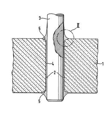
Figure 1 ~hows a vertical longitudinal ~ection of a
compo~ite body of metal and ceramic according to the
inventlon .
Figure 2 shows a magnified view of the r0gion II of
Figure 1.
Figure 3 ~how~ a vertical longitudinal ~e~t~on of a
compo~ite body of metal and cer~mic according to the
prior art.
In Figure 1, a ceramic ~atexial 1 which po8~e~e~ a
rece~ 2 going right through can be seen. With~n ~he
recess 2, a metal pin 3 i~ arra~ged ~o that it fit~
accurately and ia bondad by internal soldering 4 to the
ceramic material 1. In the magni~ied view of Figure 2,
the angle ~ of the chamfer 5, She wetting angle ~ and the
chamfer width b can be ~ean. The point of at~achm~nt 6
coincide~ with the outermo~t dizmetar of the ch~mfer 5
which i~ thu~ completely wetted with ~older over its
whole width b. By means of exce~ pre~oldqring tech~ol-
ogy, the amount of exces~ ~older pro~ided 7 i8 ~uch that
: ~
- 8 - ~2~ 2
the wetting angle ~ is thereby kept a~ ~mall as po~sible.
The ~older cros section defined by the angle ~ of the
chamfer 5 and the wetting angle ~ tran~mits the forca~ of
older shrinkage into the ceramic body 1 homoge~eou~ly
and over the area of the whole width b of the cham er 5.
In Figure 3, the refersnce labela have l:he ~ame meanings
as their equivalent~ in Figure 1 and Figure 2. However,
it can be ~een that the point of at~ach~ent 6 lies in the
middle of the chamfer 5 a~d that the wett~ng angle ~ i~
too large, resultiny in cracks 8 which m,ake ~he compo~ite
body unusable.
The composite body of the invention can be advantageou~ly
used as a duct, rectifler hou~ing, ~eal, sliding elzment,
bearing elemant, piezoelectric el~ment, pump piston,
thyristor hou~ing, overvoltage conductor, vacuum chamber,
switching tube, ignition element, diode, rock top or
~pacer block for component~ sub~ectsd to chemical,
mechanical and/or thermal ~tre~ses.
- . .
.. . ~ .
- . . -
- -- : ~