Note: Descriptions are shown in the official language in which they were submitted.
212~7~
! i . ,
I.OCRING AND UN~OCKING APPARATUS FOR AC~r~:.S DOOR
ON A PAS~;~L.~iK R~ILWAY VEHICLE
FIELD OF THE lNv~;N~l~loN
The present invention relates, in general, to a locking and
unlocking apparatus for a passenger transit type railway vehicle
and, more particularly, this invention relates to a simple and
reliable apparatus for mechanically locking and unlocking the
access doors of such passenger transit type railway vehicle which
allows for automatic locking and unlocking during normal operation,
and which will maintain the access door in a mechanically locked
condition in the event of a pressure failure in the door activating
system, and yet permits quick and easy manual unlocking in the
event of an emergency.
BACKGROUND OF THE lNV~:N'l'lON
It is generally well known, in the art, that the acces~ doors
on passenger transit railway vehicles, such as subway cars and the
like, are provided with an automatic opening and closing mechanism
which is controlled by the operator of such vehicle. It is also
well known that such access doors are normally provided with an
automatic locking mechanism that will lock such access doors in the
closed position when the vehicle is in motion to safeguard the
passengers during normal operation. These access doors, however,
must also be provided with a mechanism that will permit an override
or by-passing of the automatic locking mechanism to enable the
2l2s7~
operator or a passenger to manually open such access door in the
event of an emergency.
Typically, such an access door or pair of doors are operated
by either a hydraulic or pneumatic cylinder which is connected to
a linkage mechanism adapted to open and close the door or doors in
response to the reciprocating action of the hydraulic or pneumatic
cylinder rod. In most operating situations, the doors are locked
in place in the closed position by maint~in;ng a positive pressure
within the hydraulic or pneumatic cylinders while the doors are in
the closed position. When the doors are automatically opened by
the vehicle operator, however, the hydraulic or pneumatic cylinders
are activated in the opposite direction, thereby releasing the
positive pressure within the cylinder which maintains the access
doors in their locked position.
The emergency release device, therefore, is usually some type
of mechanical system that will release an access door from the
linkage system driven by the hydraulic or pneumatic cylinder,
thereby permitting a passenger, for example, to force such access
door open even though a positive pressure is being maintained
within the hydraulic or pneumatic cylinder. In the event of a
pressure loss in the hydraulic or pneumatic cylinder system,
however, the access doors will not be locked in the closed
position, thereby creating a hazardous condition.
SUMMARY OF THE lNv~NllON
The present invention is predicated upon a new and unique
positive mechanical locking system that can be used in combination
21257~
. _
with conventional door operating systems that does not depend upon
a positive pressure within the hydraulic or pneumatic cylinder to
lock an access door in the closed position, but rather locks the
door in the closed position mechanically. While the door locking
system of this invention can be effectively utilized in combination
with such conventional door operating system which depends on a
positive pressure being maintained in the hydraulic or pneumatic
system to keep the doors locked, thereby providing a double locking
system, whereby the mechanical system of the instant invention will
provide a positive lock in the event of a loss of hydraulic or
pneumatic pressure. Additionally, the system of this invention can
be utilized as the sole access door locking system if so chosen.
Accordingly, the apparatus of this invention will keep the doors
mechanically locked in the closed position whether or not
additional locking is provided with a positive pressure in the
hydraulic or pneumatic cylinders, and whether or not there is a
loss of pressure in the hydraulic or pneumatic system.
As is obviously necessary, the system of this invention is
further provided with a simple unlocking mechanism which will
automatically disengage or unlatch the mechanical locking apparatus
when the door opening mechanism is activated to open the access
door, and is further provided with a system which enables the
manual disengaging or unlatching of the mechanical locking
apparatus so that the access doors can be opened manually in an
emergency situation.
r 2 5 74 5
In its basic form the apparatus of this invention utilizes a
spring biased locking lever arm which is pivotally secured to a
movable access door panel. A roller, rotatably secured to the
locking lever arm at an end opposite the pivotal attachment, is
positioned so that it will engage a ramp rail structure secured to
a door frame structure adjacent the moveable access door panel when
such door panel is moving into a closed position. The ramp rail
structure is provided with two intersecting guide rail surfaces,
namely, a first rail surface at an inclined angel to the moveable
door panel, and a second rail surface disposed substantially
perpendicular to the door panel such that the first and second rail
surfaces intersect at an angle of less than about gO to form a
rail corner. The pivotal locking lever arm and the ramp rail
structure are relatively positioned so that when the access door
panel is being moved into the closed position, the roller on the
locking lever arm will roll along the first; i.e., inclined, rail
surface of such ramp rail structure, and when such access door
panel reaches a fully closed position, the roller will move beyond
the intersection of the two rail surfaces and be biased to move
perpendicular to the access door panel and engage the rail surface
perpendicular to the door panel to thereby lock such door panel in
the fully closed position.
In combination with the above-described apparatus, an
automatic unlocking means, actuated by a door opening means, is
also included. The automatic unlocking means of this invention
will push the roller from engagement with the second, or
21257~
., s
perpendicular rail surface of the ramp rail structure so that such
access door panel can be moved towards an open position, and upon
the subsequent release of the automatic unlocking means, the roller
will be caused to engage the first, inclined rail surface of such
ramp rail structure so that such access door panel can be moved to
a fully open position. For emergency situations, there is a means
provided which enables manual activation of the above-described
unlocking means.
OBJECTS OF THE lNv~ oN
It is, therefore, one of the primary objects of the present
invention to provide a simple, reliable, low cost and easy to
operate, mechanical means for locking an access door on a railway
type passenger transit vehicle which is independent of any
hydraulic or pneumatic system for opening and closing the access
door so that such an access door will be maintained in the closed
and locked position in the event of a pressure failure in the
hydraulic or pneumatic system.
Another object of the present invention is to provide a
mechanical means for locking an access door on a railway passenger
transit vehicle which is not sensitive to vertical and longitudinal
acceleration.
A further object of the present invention is to provide a
mechanical means for locking an access door on a railway passenger
transit vehicle which is simple and reliable and can be located or
relocated in different positions depending on the space available.
21~$74~
An additional object of the present invention is to provide a
mechanical means for locking an access door on a railway passenger
transit vehicle which is simple and reliable and can be easily
incorporated with different door opening and closing mechanisms and
different types of access doors.
A still further object of the present invention is to provide
a mechanical means for locking an access door on a railway
passenger transit vehicle which can be manually unlocked with
relatively good efficiency.
In addition to the above-described objects and advantages o~
the locking and unlocking apparatus of this invention, various
other objects and advantages of the present invention will become
more readily apparent to those persons who are skilled in the same
and related arts from the following more detailed description of
the invention, particularly, when such description is taken in
conjunction with the attached drawing figures and with the appended
claims.
BRIEF DESCRIPTION OF THE DRAWINGS
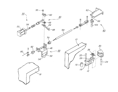
Figure 1 is an exploded isometric view of the apparatus of one
presently preferred embodiment of this invention for locking a
single sliding access door panel in a fully closed position;
Figure 2 is sectional plan view of the apparatus illustrated
in Figure 1 showing the access door panel in a position where it is
moving towards a closed position;
2I257~1 ~
_
Figure 3 is a sectional plan view substantially the same as
that shown in Figure 2 but showing the access door panel in a fully
closed and locked position; and
Figure 4 is a sectional plan view substantially the same as
that shown in Figure 3 but showing the access door panel in a fully
closed position after the locking apparatus has unlocked the door
panel.
DESCRIPTION OF A PREFERRED EMBODIMENT OF THE lNv~LlON
Prior to proceeding with a more detailed description of the
access door locking and unlocking apparatus of this invention, it
should be noted that throughout the several views illustrated in
the attached drawings, identical components which have associated
therewith identical functions have been identified with identical
reference numerals for the sake of clarity.
Referring now to the several drawings, illustrated therein is
one preferred embodiment of an access door locking and unlocking
apparatus of this invention generally illustrating a door panel 10,
of the type commonly used on passenger transit type railway
vehicles whereby a single, one piece door panel 10 is mounted to a
roller assembly (not shown) and mechanically linked to a door
opening and closing apparatus (not shown), such as a hydraulic or
pneumatic cylinder with appropriate linkage, adapted to slide the
single door panel 10 back and forth from a closed position across
a door portal (not shown) to an open position not across such door
portal. It is well known that other types of access door panels
212~7gS
r
are commonly utilized, such as double sliding doors as well as
single and double folding doors.
While the embodiment of this invention described and
illustrated here is shown as applied to a simple, one piece single
sliding door, it will become apparent that the door locking and
unlocking apparatus of this invention can be incorporated with
doors of the other types noted above, as will be subsequently
discussed.
Reference to Figure 1 illustrates a single, one piece sliding
access door panel 10, to which a locking lever arm 12, is secured,
preferably near the upper edge of such access door panel 10, and
also preferably in a location where it will be shielded from access
by vehicle passengers, such as behind an overhanging door frame
structure (not shown). The locking lever arm 12 has a first end 14
pivotally secured to a lever arm mounting base 20, and a second
end 16 having a roller 18, rollably secured thereto with pin 22,
with the axis of roller 18 vertically disposed and parallel to the
plane surface of access door panel 10. The first end 14 of locking
lever arm 12 is pivotally secured to lever arm mounting base 20
with a pin member 24 such that locking lever arm 12 is able to
pivot on pin 24 in a plane perpendicular to access door panel 10,
and is biased by torsion spring 26 to bias the pivotal motion of
locking lever arm 12 in a clock-wise direction (as viewed from the
top), which is intended to bias such pivotal motion so as to bias
roller 18 against the ramp rail structure 30 described in more
detail below.
212571~i
r
A locking support structure 30, having a first rail surface 32
at an inclined angel to the access door panel 10, and a second rail
surface 34 disposed substantially perpendicular to such access door
panel 10, is rigidly secured to a non-moving door frame structure,
such as passageway frame 19, at a position such that when the door
panel 10 is moving towards the closed position, the lever arm 12
will be biased towards such locking support structure 30, such that
roller 18 will be biased against the inclined first rail surface 32
and caused to roll upward along the inclined first rail surface 32.
In the presently preferred embodiment of the invention, the second
rail surface 34, disposed substantially perpendicular to access
door panel 12, intersects the first rail surface 32 at an angle of
less than about 90 so that continued motion of roller 18 upward
along the first rail surface 32 will eventually cause roller 18 to
move past the point of intersection of the two rail surfaces 32
and 34 so that the biasing action keeping roller 18 against the
first rail surface 32 will cause the roller 18 to be pivoted inward
and adjacent the perpendicular second rail surface 34 as the door
panel 10 reaches the fully closed position. Because the second
rail surface 34 is perpendicular to door panel 10, and therefore
perpendicular to the movement plane of access door panel 10, it
will function as an abutment against roller 18, thereby blocking
roller 18, and accordingly blocking the door panel 10 from being
returned to the open position. While the point of intersection
between the first and second rail surfaces 32 and 34 are shown as
a sharp point of intersection where the two straight surfaces
212~74~,
intersect, it should be apparent the curved surface transitioning
from one flat surface 32 or 34 to the other could be provided as
long as roller 18 will abut against at least a perpendicular
portion of the second rail surface 34 when the access door panel 10
S is fully closed to thereby maintain the door panel lO in a locked
position .
As should be apparent from the above description, the relative
positions of locking lever arm 12 and locking support structure 30
must be selected such that as the access door panel 10 is
approaching the closed position, roller 18 will be caused to roll
upward along the inclined first rail surface 32, and when such door
panel 10 reaches a fully closed position, roller 18 will be caused
to be pivoted against the perpendicular second rail surface 34
thereby locking the door panel 10 in place so that it cannot be
reopened by e~traneous forces, such as vibration, wind, vehicle
movement, and/or an unintended opening by a passenger.
Since the door panel 10 will have to be opened from time to
time to permit passengers to ingress and egress to and from the
vehicle, means must be provided to automatically unlock the above
described locking apparatus when the door opening apparatus (not
shown) is activated, and in addition, means must also be provided
to permit manual unlocking of the apparatus in the event of an
emergency situation developing.
Both of these critical functions are provided in the presently
preferred embodiment, as illustrated in Figure 1, by providing an
unlatching lever assembly 40, which will unlatch the above
- 10
21257~
described locking apparatus, and is automatically operated by an
unlocking cylinder assembly 50, and in the alternative, can be
manually operated by a manual unlocking assembly 60. Either the
unlocking cylinder assembly 50 or the manual unlocking assembly 60
will activate the unlatching lever assembly 40 that will
effectively push or lift roller 18 away from the perpendicular
second rail surface 34 so that the access door panel 10 can be at
least partially opened to a point where release of the pushing or
lifting means will cause such roller 18 to engage the inclined
first rail surface 32 which will not thereafter block the access
door panel 10 from being moved to the fully open position.
While a great variation of such means are envisioned to be
possible, one presently preferred apparatus for achieving this
result is the unlatching lever assembly 40, as illustrated in
Figure 1, which includes a two piece lever arm, namely an
activating lever arm or upper lever arm 42 and a lower unlatching
arm 44, both of which are pivotally secured to unlatching support
structure 32 by pin 46, such that an unlatch pin 48, which extends
downwardly from the outward end of such lower unlatching arm 44,
will be positioned adjacent the upper side of lever arm 12 when the
access door panel 10 is in the fully closed position. In the
embodiment shown, lever arm 12 is provided with an upwardly
extending flange member 28 against which the unlatching pin 48 is
forced to pivot lever arm 12, and accordingly pivot such roller 18
away from perpendicular second rail surface 34 to unlock the door
panel 10.
212574X
Upper lever arm 42 and lower unlatching arm 44 are partially
interlocked and are maintained in a fixed position by a torsion
spring 49. The partial interlocking is such that counter-cloc~wise
pivotal rotation of such upper lever arm 42 will cause the lower
unlatching arm 44 to pivot or rotate through the same angle, but
such that counter-clockwise pivotal rotation of lower unlatching
arm 44 will not cause any motion of upper lever arm 42.
Methods for effecting such partial interlocking are well known
in the mechanical art, and need not be described in significant
O detail here. For example, a rigid pin provided in one pivotal arm
extending through an arcuate slot in the other pivotal arm is well
known, as are other techniques.
Accordingly, a counter-clockwise turning action applied to the
upper lever arm 42, causing it to pivot or rotate to the left
(i.e., counter-clockwise as viewed from the top), will cause the
lower unlatching arm 44 to rotate or pivot through the same angle
of rotation. Such pivotal rotation of the lower unlatching arm 44
will cause such unlatching pin 48 to push against the upper edge of
such locking lever arm 12, and thereby cause roller 18 to be moved
O outward and away from perpendicular second rail surface 34, so that
such access door panel 10 can be opened.
An activating means such as the unlocking cylinder assembly 50
is provided for the purpose of activating such unlatching lever
assembly 40 as above-described. Specifically, unlocking cylinder
assembly 50, comprises a hydraulic or pneumatic cylinder or even a
solenoid 52, which activates reciprocating cylinder rod 54. The
21257~5
outward end- of cylinder (or solenoid) reciprocating rod 52 is
pivotally connected to upper lever arm 42 by pin 56. As previously
noted, upper lever arm 42 and lower unlatching arm 44 are partially
interlocked and are maintained in a fixed position by such torsion
spring 49. Torsion spring 49 further serves to bias the lower
unlatching arm 44 as necessary to position unlocking pin 48 into a
neutral position so that the locking lever arm 12 and roller 18 can
move as required to lock such access door panel 10 in place without
obstruction. When the door opening apparatus (not shown) is
activated, cylinder (or solenoid) 52 will be activated to pull
cylinder rod 54 and thereby rotate upper lever arm 42 in a counter-
clockwise direction. As lower unlatching arm 44 is mechanically
interlocked for rotation in that direction, lower unlatching arm 44
will also be rotated so that unlatch pin 48 will push lever arm 12
aside, thereby pushing roller 18 away from perpendicular second
rail surface 34 so that such access door panel 10 can be opened, as
becomes necessary.
Reference is now made to Figure 2 which illustrates the access
door panel 10 as it is moving closely towards the fully closed
position, with the roller 18 moving along the inclined first rail
surface 32. Figure 3 illustrates the arrangement of the apparatus
when such access door panel 10 is in the fully closed position with
the roller 18 abutted against such substantially perpendicular
second rail surface 34 to lock the door panel 10 in such closed
position. Figure 3, on the other hand, further illustrates the
arrangement of the apparatus after unlatching lever assembly 40 has
21257~5
been automatically activated, as above-described, to push the
locking lever arm 12 and such roller 18 away from the two rail
surfaces 32 and 34. While not shown in the drawings, this result
is achieved by activation of cylinder 52 to pull reciprocating
rod 54, thereby causing the lower unlatching arm 44 to be partially
rotated, such that unlatching pin 48 is caused to move outward,
pushing against the upper edge of locking lever arm 12 and causing
roller 18 to be moved away from such perpendicular second rail
surface 34. In this position, movement of access door panel 10
will not be blocked from motion towards the open position, and
accordingly, the door opening apparatus will cause such access door
panel 10 to be moved towards the open position, such that the door
panel 10 will no longer be locked in place, but will instead be in
a position substantially as shown in Figure 2.
For manual unlocking of the access door panel 10, a manual
activating means such as manual unlocking mechanism 60 is utilized
to manually activate the, above-described, unlatching lever
assembly 40. The manual unlocking mechanism 60 includes manually
operated linkage which, in essence, does the same thing that
unlocking cylinder assembly 50 does, and comprises a by-pass lever
support structure 62, to which a by-pass lever 64 is pivotally
mounted on a pin 66. One end of a push rod 68 is connected to the
by-pass lever 64 by linkage 68, and the other end is inserted
through an eyelet 70 at a position where it will abut against the
lever portion of lower unlatching arm 44, such that a manual
pulling force on by-pass lever 64 (as indicted by the arrow), will
212574~
result in a pushing action on push rod 68, and accordingly a
rotation of such lower unlatching arm 44 as necessary to cause the
roller 18 to be moved away from such substantially perpendicular
second rail surface 34 and disengage the locking action, as has
been described above. Because the upper lever arm 42 and such
lower unlatching arm 44 are only partially interlocked, such lower
unlatching arm 44 can be rotated as described without also rotating
upper lever arm 42, and accordingly without having to overcome the
rigid fixation of such upper lever arm 42 and the cylinder rod 54.
As is illustrated in Figure 1, a cable 80, extending through
an eyelet 82 can be attached to the end of such lower unlatching
arm 44 opposite push rod 68, to provide an alternate method for
manual activation of unlatching lever assembly 40. A pulling force
on cable 80 will cause the lower unlatching arm 44 to pivot and
unlatch the locking action as described above.
While a preferred embodiment of the mechanical door locking
apparatus of the present invention has been described in detail
above, it should be apparent to those persons skilled in the art
that various other embodiments, adaptations and modifications of
the invention could be made without departing from the spirit and
scope of the invention.
For example, while the above described embodiment is described
as utilized in combination with a single access door panel of the
sliding type, it should be apparent that the inventive apparatus
could be adapted for use on other types of door panels, including
double door panels and even folding single and double door panels.
2I2S 74S~
.
For example, for use with double door panels, the locking lever arm
12 could be secured to one door panel as described above, with the
locking support structure 30 secured to the other door panel. But
for the fact that both elements will be moving elements and
positioned so that they will move towards each other as the doors
move towards the closed position, the locking mechanism would
operate virtually the same. Positioning variations may have to be
made depending upon whether the door panels abut or overlap each
other. It should be readily apparent the a similar locking
apparatus could be designed for folding door panels as well, as the
outer edge of a folding single door panel, or outer edges of double
folding door panels move generally horizontally as they approach a
fully closed position, and could therefore, be locked in
substantially the same way with substantially similar apparatus.
While the above described locking apparatus describes a
pivotal motion of locking lever arm 12 towards the door panel 10,
is should be readily apparent that the reverse pivotal motion could
be utilized by merely positioning the locking support structure 30
on a door frame structure displaced inwardly from the access door
panel 10. As should also be obvious, the relative positions of the
locking lever arm 12 and the locking support structure 30 could be
reversed if so desired so that the locking support structure 30 i9
virtually pushed under lever arm 12 as the door panel is closing,
with virtually identical locking results.
With regard to the automatic and manual unlocking apparatus
described, is should be quite apparent that the apparatus described
- 212S7~
is but one of a significant number of variations that could be
devised and designed, as the only requirement be that some means be
provided to displace the roller pin 18 from the perpendicular
second rail surface 34 until the access door panel 10 starts to
open. It should be quite apparent that a great number of different
devices could be designed to accomplish this purpose, which could
even include a spring loaded ramp rail structure that can be
retracted inwardly like a conventional door latch, away from the
roller 18 to unlatch the lock.
While the manual unlocking apparatus described functions to
manually unlock the door panel utilizing the same apparatus
utilized by the automatic unlocking system, it should be apparent
that an entirely different systems could be utilized for the
automatic and manual unlocking apparatus. Clearly, therefore,
other variations, embodiments, adaptations and modifications could
be made without departing from the spirit and scope of the present
invention, as defined by the appending claims.