Note: Descriptions are shown in the official language in which they were submitted.
2125863
WO 94/09909 PCT/SE93/00846
1
Hydrocyclone plant
The present invention relates tc> a hydrocyclone plant
for treating fibre suspensions comprising a multiplicity
of,elongated hydo_~ocyclone bodies, each of which has an
apex end and a base end, and is designed with an ex-
terior sealing surface having a circular cross-section.
In the hydrocyclone plant there is a wall provided with
circular holes, into which the respective hydrocyclones
are inserted, so that the sealing surfaces extend
through the holes. Circular sealing rings extend around
the respective sealing surfaces and are situated in the
holes of the wal7_ to seal between the sealing surfaces
and the wall.
In conventional hydrocyclone plants of this kind the
sealing rings arE: made of an elastic rubber compound
having a a relatively poor resistancy to the chemicals
which can be found in the fibre suspensions which are
treated. Thus, the chemicals might affect the sealing
rings of rubber, so that these become hard or are
dissolved, which has the consequence that the seal
between the sealing surfaces of the hydrocyclone bodies
and said wall becomes unreliable. In addition, depending
on the kind of chemicals the sealing rings of rubber
might swell, so that the hydrocyclone bodies become
jammed in the wall, which makes it difficult to dismount
the individual hydrocyclone bodies.
It is true that t:he sealing rings could be made of
existing chemical resistant rubber compound, whereby the
problem of unreliable sealing or jamming of the hydro-
cyclone bodies could be eliminated. However, such
chemical resistant: rubber compounds are too expensive to
justify their use. in a hydrocyclone plant, which may
2125863
WO 94/09909 PCT/SE93/00846
2
comprise hundreds of hydrocyclone bodies, each of which
requires two sealing rings.
The object of the present invention is to provide a
hydrocyclone plant, in which the required seals between
hydrocyclone bodies and walls are reliable, and in which
the hydrocyclone bodies do not risk getting stuck in the
walls, without making the plant more expensive than
conventional plants.
This object is obtained by means of a hydrocyclone plant
of the kind described initially, which is characterized
in that - a) each sealing ring is radially cut through
to form two opposite free ends on the sealing ring as
seen in the circumferential direction of the sealing
ring, the sealing ring being stiff enough to prevent it
from loosening from its hydrocyclone body in the direc-
tion transverse to the latter, when the hydrocyclone
body is dismounted from the wall; - b) the sealing
surface of each hydrocyclone body has a radial extension
which increases along the sealing surface in the
direction towards the base end of the hydrocyclone body
and is provided with a projection extending axially
along the sealing surface and between the free ends of
the sealing ring on the sealing surface; c) each sealing
ring is dimensioned such that it is insertable into any
one of the holes of the wall, when the sealing ring is
situated in a first position on its sealing surface, and
is expanded by the sealing surface to seal between the
wall and the sealing surface, when the sealing ring is
inserted into any one of the holes of the wall and is
situated in a second position on the sealing surface, in
which the sealing surface has a greater diameter than in
said first position; and - d) each sealing ring is
provided with a radially outwardly directed stop member,
2125 8 fi~
WO 94/09909 PCT/SE93/00846
3
which is adapted to abut against the wall, so that the
sealing ring is entrained by the wall from said first
position to said second position, when the sealing ring
is inserted into any one of the holes of the wall and
the hydrocyclone body on which the sealing ring is
applied is displaced with its apex end leading through
said holes in the wall.
Hereby the sealing rings need not be elastic but can be
made of an inexpensive moulded plastic compound which is
resistant to the chemicals which can be found in the
fibre suspensions which are treat=ed.
Advantageously the projection on each sealing surface is
dimensioned such that it substanl:ially fills up the
space which is formed between thE: sealing surface, the
wall and the free ends of the sealing ring on the
sealing surface, 'when the sealing ring is in said second
position and is expanded by the ~>ealing surface. Since
the free ends of the sealing ring are moved away from
each other, when the sealing ring expands during dis-
placement of it along the sealing surface towards said
second position, 'the projection suitably has a circum-
ferential extension on the sealing surface which
increases along the sealing surface in the direction
towards the base end of the hydrocyclone body.
According to a preferred embodiment of the hydrocyclone
plant according to the invention each sealing surface
has a first cylindrical portion, a second cylindrical
portion having greater diameter than the first portion,
and a conical portion tapering from the second cylind-
rical portion to the first cylindrical portion. In this
case the projection on the sealing surface of each
hydrocyclone body suitably has a circumferential
212563
WO 94/09909 PCT/SE93/00846
4
extension which increases along the conical portion of
the sealing surface in the direction towards the base
end of the hydrocyclone body.
The invention is explained more closely in the following
with reference to the accompanying drawings, in which
figure 1 shows a hydrocyclone plant according to the
invention,
figure 2 shows a detail of the hydrocyclone plant
according to figure 1 with a hydrocyclone body in a
dismounted position,
figure 3 shows the same detail as figure 2, but with the
hydrocyclone body in a mounted sealing position,
figure 4 shows a section along the line IV-IV in
figure 2,
figure 5 shows a section along the line V-V in figure 3,
figure 6 shows a part of a hydrocyclone body in the
hydrocyclone plant according to figure 1,
figure 7 shows a sectional view along the line VII-VII
in figure 6,
figure 8 shows a sealing ring for the hydrocyclone body
according to figure 6, and
figure 9 shows a view along the line IX-IX in figure 8.
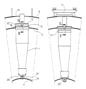
The hydrocyclone plant shown in figure 1 comprises a
multiplicity of elongated hydrocyclone bodies 1, each of
212fi8fi3
~fO 94/09909 PCT/SE93/00846
which tapers from a base end 2 to an apex end 3. Three
cylindrical vertical walls 4-6 are arranged concen-
trically with each other so that a cylindrical space 7
for a created heavy fraction is defined by the innermost
5 situated wall 4, an annular space 8 for a fibre suspen-
sion to be treated is defined by the innermost wall 4
and the intermediate wall 5, and an annular space 9 for
a created light fraction is defined by the intermediate
wall 5 and the outermost situated wall 6. The hydro-
cyclone bodies 1 extend radially in the annular space 8
and are regularly allocated around the cylindrical space
7. Each hydrocyclone body 1 extends at its base end 2
through a hole in the intermediate wall 5 and at its
apex end 3 through a hole in the innermost wall 4. In
the outermost wall 6 there are holes 10, through which
the hydrocyclone bodies 1 can be mounted on and dis-
mounted from the hydrocyclone plant. The holes 10 are
closed by removable lids 11.
Each hydrocyclone body 1 is designed at its base end 2
with an exterior sealing surface 12, which comprises a
first circular cylindrical portion 13, a second circular
cylindrical portion 14 having a greater diameter than
the portion 13, and a conical portion 15 tapering from
the portion 14 to the portion 13.. The sealing surface 12
is axially defined by two stop members in the form of
flanges 16 and 17 on the outside of the hydrocyclone
body 1.
Around each sealing surface 12 there is extending a
circular sealing ring 18, which consists of a resilient
compound and which is radially cut through to form two
opposite free ends 19,20 on the sealing ring 18 as seen
in the circumferential direction of the sealing ring 18.
The sealing ring 18 is stiff enough to be prevented from
2125B 63 -
WO 94/09909 PCT/SE93/008~(~
6
loosening from its hydrocyclone body 1 in the direction
transverse to the latter. Axially along the hydrocyclone
body 1 the freedom of movement of the sealing ring 18 is
limited by the flanges 16 and 17. The sealing ring 18 is
provided with a stop member in the form of a radially
outwardly directed flange 21 having a greater trans-
versal extension than the holes of the wall 5 and
situated at the axial end of the sealing ring 18 which
is closest to the base end 2 of the hydrocyclone body 1.
Each sealing surface 12 is provided with a projection
22, which extends axially along the sealing surface 12
and between the free ends 19,20 of the sealing ring 18
on the sealing surface 12. The extension of the projec-
Lion 22 in the circumference of the sealing surface 12
increases continuously along the conical portion 15 in
the direction towards the base end of the hydrocyclone
body 1.
To seal against the innermost wall 4 each hydrocyclone
body is provided at its apex end 3 with a sealing
surface 23, a sealing ring 24, flanges 25,26, and a
projection 27 (figures 2 and 3), which are formed
analogous to and has the same function as the above
described corresponding components at the base end 2 of
the hydrocyclone body 1 and therefore need not be
further explained.
When mounting a hydrocyclone body 1 it is brought with
its apex end 3 leading in the direction of movement into
any one of the holes 10 of the outermost wall 6 and
further through fitting holes in the walls 5 and 4 to
the position shown in figures 2 and 4. In this position
the sealing ring 18 is situated on the cylindrical
portion 13 of the sealing surface 12 and is inserted
21258 6 3
..J'VO 94/09909 PCT/SE93/00846
7
into the hole of the wall 5, so that the wall 5 abuts
against the flange 21 of the sealing ring 18. When the
hydrocyclone body 1 is brought further into the holes of
the walls 4 and 5 to the sealing position shown in
figures 3 and 5 'the sealing ring 18 is entrained by the
wall 5 and is expanded by the conical portion 15, so
that the sealing ring 18 seals between the wall 5 and
the sealing surface 12, when the. sealing ring 18 has
been entrained to the cylindrical portion 14 of the
sealing surface .L2. The projection 22 is dimensioned
such that it sub:~tantially fills up the space which is
formed between the sealing surface 12, the wall 5 and
the free ends 19,.20 of the sealing ring 18, when the
hydrocyclone body 1 is in the sealing position shown in
figures 3 and 5.
When dismounting any hydrocyclone body 1 from the
hydrocyclone plant the hydrocyclone body 1 is pulled
radially outwardly from the walls 4-6. The sealing ring
18 of the hydrocyclone body 1 is entrained by the wall
5, so that the sealing ring 18 glides along the cylind-
rical portion 14 of the sealing .surface 12 towards the
flange 17. When t:he sealing ring 18, which is in a
yielded expanded state, passes the conical portion 15 it
springs to a smaller diameter than the hole of the wall
5. The sealing ring 18 is therefore easily released from
the wall 5, when the sealing ring 18 reaches the cylind-
rical portion 13 and abuts again:~t the flange 17.