Note: Descriptions are shown in the official language in which they were submitted.
'~'0 93~13411 2 1 2 6 5 S ~ P ~ /US92/11286
-
-- 1 --
ANATYTE AND P~ M~A~URI~G S~SOR A~S~RT Y A~D M~TUOD
The present invention is related to an analyte sensor
assembly apparatus and method for measuring coupled analytes. More
particularly, the present invention relate6 to an apparatus of a
carbon dioxide and pH sensor assembly for measuring both in fluid
samples .
BACKGROUND OF THE ~VENTION
Numerous methods and apparatus exist in the art for
measuring chemical components of fluids and current technology
utilizes many types of sensors for detecting components and analytes
in numerous types of fluids. For example, carbon dioxide and pH
15 sensors are used for measuring these components in various fluids
including gases and liquids. For instance, the mea6urement of blood
gases, along with the pH from a sample of arterial blood, give6 the
state of the acid base balance or the effectiveness of both the
re6piratory and cardiovascular 6ystems of the human or vertebrate
20 body. Measuring the blood gases usually involve6 a measurement of the
partial pre6sures of oxygen and carbon dioxide along with the
measurement of the pH since carbon dioxide dissolved in the aqueous
solution can affect the pH through the presence of carbonic acid.
These are examples of coupled snalytes.
It is conventional practice in many of the existing
measurement methods, even where the fluid is a liquid or liquid with a
dissolved gas with or without the pre6ence of 601id6 to tran6port a
sample to a central location for testing. With centralized testing,
the bulky, stationary, elaborate and sophisticated equipment performs
30 the analy8is on a practically endle6s number of 6amples. Originally,
this equipment employed carbon dioxide sensor like the Severinghaus
W O 93/134ll P ~ /US92/11286
212 655 ~ 2 -
potentiometric sensor for a qualitative and/or quantitative measure of
carbon dioxide. This sensor has a gas-permeable membrane between the
sample solution for measurement and the measuring cell. The cell has
a pH-sensing glass electrode, a reference electrode, and an
5 intermediate electrolyte layer. Recently, more sophisticated carbon
dioxide sensors have utilized polymeric membranes like those of the
combined pH and carbon dioxide sensor of U.S. Patent 4,818,361.
Al60, recent attempts have been made to introduce more
portable equipment into the marketplace of fluid analysis. An example
10 of thi6 is the qualitative and/or quantitative measurement of
constituents or analytes of blood. The bulky stationary equipment is
fairly expensive and the procedures for its use can be cumbersome
depending on the type of fluid to be measured. For instance,
mea6uring blood gases from the arterial blood sample involves:
15 drawing the blood sample in a syringe, immersing it in ice and
transporting it quickly to the lab where the equipment is usually
located for a measurement of the gases. More portable devices would
shorten or overcome transporting the sample to the measuring equipment
at a fixed location. For ex~mple, portable sensing units which can be
20 coupled to a digital readout device would be useful at the patient's
bedside in a manner similar to a way that temperatures are measured at
the patient bedside.
U.S. Patent Nos. 3,000,805 and 3,497,442 show two such
devices. The former has electrodes located on a syringe plunger and
25 the latter has electrodes placed on the syringe well to conduct the
measurements. The electrodes of these sensors may be particularly
sensitive to small sample volumes 6ince they consume oxygen in their
operation. In U.S. Patent No. 5,046,496, Applicants' assignee
describes and claims a portable blood gas sensor which includes
30 sensors fabricated using a conventional silk screening process where
~ 93/l34ll 2 1 2 6 5 ~ ~ PC~r/US92/ll286
-- 3 --
the electrodes are screened on to a ceramic substrate. Typically,
these electrodes have the conductor along with an electrolyte and
analyte permeable polymeric membrane that cover6 the sensor. Some of
these membranes may be hydratable membranes by water vapor permeation
5 and they can be stored in a dry state and hydrated just prior to use
as in U.S. Patent No. 4,818,361. The more portable the equipment the
larger the demand for the miniaturization of the electrodes that still
produce precise outputs for the analyte concentration or tension.
SUMMARY OF THE INV~TION
It is an object of the present invention to provide a sensor
apparatus that utilizes analyte electrodes where each electrode has
sensitivities for the analytes to be measured and where the analytes
are water soluble analytes that upon solublization in water can
influence the pH.
The sensor apparatus has in its broadest aspect a holding
means for electrodes and for electronic conductive patterns at least
two analyte electrodes, at least one reference electrode, a fluid
circuit means in fluid contact with the electrodes, analyzing means,
and the electrical circuitry means.
The at least three electrodes are held by the holding means
in spaced apart relationship to each other and in electrical
connection with electronic conductive patterns of the electric
circuitry means which is also held by the holding means in insulated
fashion for conveyance of electrical signals from the electrodes.
The analyte electrodes have ion selective membranes and/or a
particular electrolyte composition that is selected to favor the
conversion of the ionic potential to electronic potential of one
analyte over the other. Each electrode has a sensitivity of the
analytes to be measured but the sensitivities are different in each
30 electrode. Both of the ion selective membranes have a first and
W 0 93/13411 2 12 6 5 5 ~ P ~ /US92/11286
-- 4 --
second side and the membranes are positioned in the respective
electrodes for one side to be in contact with the electrolyte of that
electrode and for the other side to bè available for exposure to the
fluid circuit. The fluid circuit can have a storage fluid, hydrating
5 fluid, analyte-containing fluid, or calibration fluids for analysis or
a mixture of two of these. Additionally, the membrane of each
electrode holds the respective electrolyte in contact with the
conductor of that electrode.
The reference electrode can be an electrochemical half-cell
lO or second order electrode that is provided in order to establish a
substantially accurate and constant comparative potential. The
reference electrode either with or without a membrane can have as an
electrolyte the fluid that is in its vicinity in the fluid circuit
means. Additionally, the electrolyte can include a metal cation of
15 the electrode.
The electrodes are arranged further on the holding means to
match the fluid circuit means so that the membranes of the analyte
electrodes can contact the fluid in the fluid circuit. In this
arrangement the analyte electrodes can contact the storage fluid,
20 hydration fluid, calibration or standardized fluid, sample fluid, or
all of these at different times when they are present in the fluid
circuit mean6. The reference electrode can also contact one or more
of these fluids either in axial or in no~ l alignment with the
analyte electrodes. The contact can be from channels or conduits
25 having the fluid in a flow-through or nonflow-through fluid circuit
means. The channel or channels can be in a cover encompassing the
holding means for the electrodes or on a holder or card that slides
into a recording instrument that has the electrodes held in a
stationary position for the contact.
_- W 0 93/13411 ~ 5 9 PCT/US92/11286
The electric circuitry mean6 can be prlnted wire circuitry
for the portion that i6 held by the electrode holding means. This
electronic conductive pattern means portlon of the circuitry allows
for electrical connection of the electrodes to each other through one
5 connection and for conveyance of the electronic potential to the
analyzing means. Another portion of the electrical circuitry means
can be a cable to convey electrical impulses from the holding means to
the analyzing means.
The anslyzing means receives digital or analog input and
10 produces digital and/or analog output from the input via the
simultaneous solution of the following equations:
delta mVAl = - SElAl x delta pH - SElA2 x log A2f/A2i Equation 1
delta mVA2 = - SElA2 x delta pH - SE2A2 x log A2f/A2i Equation 2
A2f = A2ixlOn Equation 3
where n = ~SE~,Al x delta mVAl - S~lAl delta mVA2
[-SE2Al x SElA2 + SElAl x SE2A2~
20 Alf = ~l~B mY~l t ~EL9_ ~ lQg A2f/A2i ~ Ali Equation 4
-SElAl
where:
delts mV = change in millivolt~
25 Al = first analyte
A2 = second analyte
El = electrode constructed to favor the first analyte
E2 = electrode constructed to favor the second analyte
SElAl = sensitivity of the electrode favoring the first
analyte for the first analyte
SElA2 = sensitivity of the electrode favoring the first
analyte for the second analyte
W 0 93/13411 ~ 6 s 5 S P ~ /US92/11286
-- 6
SEZAl = sen~itivity of the electrode favoring the second analyte for the fir6t analyte
SEZA2 = sen6itivity of the electrode favoring the second
analyte for the second analyte
5 f = final mea6urement
i = initial mea6urement
In a narrower a6pect of the present invention, the first
analyte is the hydrogen ion concentration 80 that the first analyte
electrode i6 a pH electrode. The second analyte i~ a carbon dioxide
lO and the 6econd analyte electrode is a carbon dioxide electrode. The
- electrode holding means is a nonconducting substrate suitable for
attachment of the pH, carbon dioxide, and reference electrodes spaced
apart from each other and connected to printing wiring circuits for
conveyance of the electronic potential from the electrode6 to the
15 analyzing means.
BRIEF D~SCRIPTION OF TU~ DRAWINGS
Figure la is a top planar view of the one side of the
6ubstrate or wiring board of the pre6ent invention, having an
arrangement of two analyte 6en60r6 with one reference electrode with
20 accompanying electronic conductive pattern6 of the electric circuitry,
and Figure lb show6 a portion of the opposite slde.
Figure 2 is a planar view of the one side of the substrate
or wiring board of the present invention having two analyte sensor6
(one analyte and pH) with two reference electrodes spaced apart from
25 each other and from the axis of the analyte electrodes and
accompanying electronic conductive patterns and al60 having a
thermistor.
Figure 2b is a planar view of the other side of the wiring
board (substrate) of Figure Z having a resi6tor and a heater that
30 traver6e6 the board and a number of lead6 through the board from the
..~
'''O 93/13411 2 1 2 6 ~ ~ S PC~r/US92/11286
side depicted in Figure 2 to provide an external electrical connection
from the board.
Figure 3 shows a matching fluid circuit means for the
substrate in Figures l, lb, 2 and 2b.
Figure 4 is a schematic of the circuitry including the
analyzing means.
Figure 5 is a graph of the millivolts (mV) along the
ordinate versus time in seconds along the abscig6a for the analy6is of
two analytes, carbon dioxide and hydrogen ion (pH) for a blood
lO sample.
DETATT~n DESCRIPTION OF T~F l~V~;~LION
Similar numeral6 are used throughout the drawings to denote
the same feature in each of the drawings.
The holding means ll with electrode6 and the a6sociated
15 portion of the electrical circuit means of the electrochemical sensor
apparatus of the present invention as 6hown in Figure l have
particular shapes for the components. Other shapes than those shown
in Figure l that are known to those skilled in the art for the
particular components can be used.
The electrode and circuit holding means ll may be produced
from any number of well known layered circuit technologies as, for
example, thick film, thin film, plating, pressurized laminating and
photolithographic etching of a combination of two or more of these;
however, the thick film technique is preferred for all of the
25 components. Of course, it would be possible to produce the analyte
electrodes by thick film process snd the reference electrode by thin
film proce6s. The holding meanf~ ll can be of any shape adequate to
hold the electrodes and electric circuit; one suitable example is a
printed wire board substrate.
W o 93/13411 ~ i 2 6 ~ S S PC~r/US92/11286
-- 8 --
The holding means, hereinafter in the specification referred
to as the substrate, ll can be any glass or ceramic including sheet or
chip or nonconducting substrate like wood or nonconducting polymers or
commercially available frit that can be used as the substantially
5 smooth flat surface of the substrate layer ll. Nonexclusive examples
include borosilicate glass as is known to those skilled in the art for
producing thick film or layered circuits. A nonexclusive and
preferred example of which includes a ceramic base having around 96%
Al203 such as that available commercially from Coors Ceramic Company,
lO Grand Junction, Colorado. The substrate layer ll can be and
preferably is essentially flat with two sides and any substrate known
to those skilled in the art for forming printed wiring circuits can be
used. It is preferred that the composition of the substrate can
endure the presence of electrolytes that have acidic or basic pH and
15 remain unaffected for a substantial period of time.
Substrate ll can have several layers to form the electrodes
and associated circuitry. One layer is a patterned metallic layer 12
with a number of extensions which act as the electric conductive
pattern portion 18 of the electrical circuit means, collectively
20 referred to as 22, between a voltage or current source (not shown)
that is external to the substrate ll. Each extension can have a
component (electrode conductors) at its end. The several extensions
also have the ability to transmit voltage changes from the components
of the substrate ll to the analysis means (shown in Figure 4).
The patterned metallic layer 12 is formed by printing pastes
deposited onto a substrate in the desired pattern to act as ohmic
conductors. Nonexclusive examples of suitable heat resisting metals
include: noble metals such as platinum (Pt), ruthenium (Ru),
palladium (Pd), rhodium (Rh), iridium (Ir), gold (Au) or silver (Ag)
30 or other metals traditionally used in Severinghaus potentiometric
~ 93/134ll 2 1 ~ S 5 ~ 5 P ~ /US92/11286
sensors. A nonexclusive but preferred example of a suitable paste is
a silver pa6te of the type produced and svailable from Electro-Science
Laboratorie6, Inc. under the trade de6ignation ESL 9912. The metallic
layer 12 i8 dried to produce the above noted conductive pattern 18
5 which comprise the conductive pathways 20, 22, and 24 of Figures 1 and
2 and the external leads 26, 28, and 30 of Figure lb. Any method
known to those skilled in the art for producing a sufficient thickness
of metallic tracing can be u6ed. Preferably, the silver paste6 are
oven dried and fired at a high temperature in a furnace. Firing can
10 be accomplished at a temperature in the range of around 800~C to
around 950~C for a period of around 1 to 20 minutes. With this
procedure, the thickness of the layer of the metallic conducting
tracing is usually in the range of around 0.0005 to 0.001 inches.
Although the aforementioned are preferred conditions, general
15 conditions for obt~in;ng a proper thickness can be used where the
thickness can be generally range from about 0.0004 to 0.0015 inch.
The aforementioned conductive pattern6 18 are encapsulated
with a glass ceramic mixture or a ceramic insulating material such as
alumina or spinal. This encapsulation insulates the pathways and can
20 range from a total encapsulation to encapsulation except at the end of
the metallic pattern.
The encapsulation of the metallic patterns can range from
encapsulating each from the other to a sufficient degree for
electrical insulation of the conductive patterns and any conductive
25 layer~ from each other. As shown in Figure 1, the encapsulant can
extend across the whole board from edge to edge as generally shown at
numeral 14. Preferably, the thickness of the encapsulant layer is
~ that which is adequate to seal the underlining metallic layer and to
provide insulation for the metallic patterns. Preferably, the
30 thicknes8 of the layer is around 20 to around 30 microns. Preferably,
W O 93/l34ll ~ ~ ~ 6 S S S PC~r/US92/11286 _
-- 10 --
the glass composltion for the encapsulant as with the substrate 11 is
selected to possess good chemical stability and/or moisture
resistance. Also, the metallic and encapsulant materials are selected
so that they can endure the presence of an electrolyte in a similar
5 manner as the substrate composition. A most preferred glass ceramic
mixture useful as the encap~ulant is the type produced and available
from Electro-Science Laboratories, Inc. under the trade designation
ESL 4903.
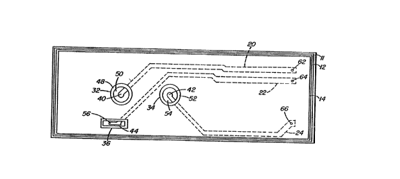
As can best be seen in Figures 1 and 2, the substrate 11 is
10 provided with a number of electrodes, 32, 34, 36, and 38, and more
particularly, electrodes useful in the measurement of a fluid analyte
that is 601uble or dissociates in liquid, for in6tance water, to
influence the pH of the liquid. A suitable example is carbon dioxide
in a fluid like blood in the measurement of blood gase6. Other
15 analytes include those that are water soluble or dissociate in water
snd upon solubllization or dissociation influence the pH of water in a
me~surable manner. Nonexclusive examples of such analytes include:
carbon dioxide, ammonia, sulfur dioxide, nitric oxide, and halides
like chlorine, bromine, and iodine, and acids which do not dissolve in
20 water to form a hydrogen ion but which have more than a certain degree
of vapor pressure, like acetic acid, ammonia gas. This a~60ciation of
analytes with the pH is hereinafter referred to as coupled analytes.
The aforementioned electrodes 32, 34, 36, and 38 are
preferably produced by one of the layered circuit technique6. This
25 involves leaving the respective shaped end6 uncovered while the rest
of the metallic patterns are completely covered by the encapsulant.
The conductors 40, 42, and 44 of Figure 1 and in addition 46 of
Figure 2 may be masked during the encap6ulation to keep them suitably
uncovered by the encapsulant for the addition of active materials
30 (e.g. electrolytes and polymeric membranes) to produce the electrodes
~ ~ 93/13411 212 6 5 5 ~ PC~r/US92/11286
on the surface of the substrate layer ll. This process involves
masking the electrodes by the use of a polymer film coating on the
screen used to screen print the encapsulant. This leaves the
underlying silver exposed to form the conducting portion of the
5 analyte and reference electrodes and the conducting pattern 18 on the
substrate ll. It is also possible to use multiple layers of the
metalllc conductive layer and/or encapsulant, and the outer layer of
the encapsulant may be solvent or thermoplastically bondable and may
include polymers, as for example, acrylates or polyvinyl chloride as
lO the major component in the encapsulant. The purpose of the outer
coating or encapsulant is to enhance bonding of the active materials
and, in particular, to provide a reliable surface for the attachment
of the liquid or solid film type membrane materials. The geometry of
the several electrodes could be made by a laser beam to carve or cut
15 or trim the electrode; however, they are preferably prepared by the
aforementioned layered circuit technique.
Each of the analyte electrodes are fabricated with
electrolyte and membranes to perform their specific task and may be
selected from many commercially available electrode components. The
20 two analyte electrodes 32 and 34 on the substrate ll in Figures l and
2 are prepared to maximize the electronic response from one of the
analytes to be measured over the other. Either one or both of the
membrane 48 and electrolyte 50 for electrode 32 are constructed to
favor to some degree the conversion of the ionic potential of one
25 analyte to an electronic response for the electrode. Membrane
materials known to those skilled in the art are selected to enhance
the permeability of the one analyte over the other and/or electrolyte
materials known to those skilled in the art are selected in favor of
the one analyte over the other. For the latter the electrolyte can be
30 buffered to minimize the ionic potential of the other analyte while
W O 93/13411 - P ~ /US92/11286
?,~?,6S~
- 12 -
the desired analyte's ionic potentisl i6 favored. The membrane 52
and/or electrolyte 54 for electrode 34 can be selected in a similar
manner to favor the conversion of the ionic potential to electronic
potential for the analyte not favored by electrode 32.
In the preferred embodiment of the present invention in
accordance with both Figures 1 and 2, one electrode, for instance, 32
is a pH electrode and the other electrode 34 i8 a C02 electrode. Each
electrode i6 fabricated with a membrane which maintains their
respective electrolytes in a fluid tight manner in the cavities or
10 openings in which the electrodes are positioned. The pH electrode 32
and the C02 electrode 34 may be similar in regards to the circuit
geometry and electrolyte and may be provided with membranes suitable
for the particular characteristic being measured.
Electrode 32, preferably, a pH measuring electrode, has an
15 electrolyte 50 in contact with the conductor 40. The electrolyte
preferably has an acidic pH in the range of around 3 to around 4. A
suitable acid electrolyte is an aqueous 601ution of potassium
hydrophosphate (KH2P04). A most suitable and preferred aqueous
electrolyte is one from 13.6 grams of potas6ium hydrophosphate in one
20 liter of deionized water. Preferably, the membrane for the pH
electrode is a polyvinylchloride polymer, which is plasticized, and
has the ionophore and the anion blocker. This membrane is prepared as
the dried residue of a solution having the polyvinylchloride polymer
which is a very high molecular weight polymer having a molecular
25 weight in the range of around 10,000 to around 500,000 weight average
molecular weight. Preferably, the plasticizers are o-nitrophenyl
octyl ether (NPOE) and bis-(ethylhexyl)adipate or
di-2-ethylhexyladipate (BEHA) and the ionophore tridodecylamine and
the potassium tetrakis chlorophenylborate (KTClPB) anion blocker in
30 the cyclohexanone solvent. The use of the very high molecular
2126555
93/13411 P ~ /US92/11286
polyvinylchloride polymer reduces the permeability of the membrane to
carbon dioxide. The acidic electrolyte suppresses the reaction of the
carbon dioxide and water to minimize the extent to which the carbon
dioxide changes the pH. This favors the electronic response for the
5 pH measurement since the carbon dioxide produces little electronic
response.
Electrode 34, which is preferably a carbon dioxide
electrode, can have a membrane that is fabricated from a wide range of
commercially available carbon dioxide permeable polymeric materials.
10 As with the pH electrode, the electrolytes of the C02 electrode 34 is
bound by its respective membrane. The electrolyte for the carbon
dioxide sen~or is initially at an alkaline pH in the range of greater
than 7 to 14 and most preferably at a pH of around 8 with the presence
of bicarbonate ions. A suitable formulation for the electrolyte is
15 0.02 moles of sodium bicarbonate in a liter of deionized water. The
membrane for the carbon dioxide electrode holds the electrolyte in
contact with the conductor; preferably, the membrane is water vapor
porous and is made of a high molecular weight polyvinylchloride
polymer that is plasticized and has the ionophore, tridodecylamine, in
20 an organic solvent. A suitable membrane i8 produced from a
polyvinylchloride powder which i8 a high molecular weight having a
weight average molecular weight in the range of 10,000 to 500,000.
Although this is the same range as for the pH electrode the molecular
weight for the carbon dioxide electrode is lower than that for the pH
25 electrode. The lower molecular weight polyvinylchloride membrane
allows transport of the carbon dioxide through the membrane since it
is more permeable to carbon dioxide. This PVC is plagticized with
~ NPOE and BEHA in nitrobenzene with the presence of the ionophore.
Preferably, KTCLPB is the anion blocker and cyclohexanone is solvent.
30 The membrane most preferably is formed of the dried residue of the
W O 93/1341l ~ P ~ /US92/11286
~,~26~S ~) '~
- 14 -
601ution that has the following percentages by weight, high molecular
weight, polyvinylchloride around 5, NPOE around 5, BEHA around 5,
nitrobenzene around 5, tridodecylamine 1.78, pota6sium tetrakis
(4-chlorophenyl) borate 0.9, and 76 cyclohexanone solvent. The carbon
5 dioxide di6601ves in the aqueous electrolyte and the pH changes so
that the ionic potential of the electrolyte changes and this is
converted at the conductor of the electrolyte to an electronic
potential.
Although the aforedescribed pH and carbon dioxide electrodes
10 were described as hydrated electrodes in that the electrolyte was an
aqueous solution, the electrolyte can be a dried material or a gelled
electrolyte. The dried electrolyte would require hydration prior to
u6e through the membrane which i6 permeable to at lea6t water vapor.
In addition to the electrodes, other polymeric materials,
15 plasticizer6, ionophore6, anion blocker6 and sol~ents can be used
which are known to those 6killed in the art. The material8 8hould be
used with electrolytes that favor ~~ Izing the response of one
analyte over the other for one electrode while ~ 1zing the respon6e
for the other analyte in the other electrode. Nonexclu6ive examples
20 of polymer6 for membranes that are permeable to carbon dioxide and
other gases that are 601uble in water and water vapor include
cellulose acetate, polybi6phenol-A carbonate
(polysiloxane/poly(bisphenol-A carbonate) blocked copolymer;
poly(methylmethacrylate), poly(vinylidene chloride), polystyrene,
25 lower alkyl acrylate and methacrylate copolymers and polymers,
polyurethane, and 6ilicone rubber. Other suitable pla6ticizer6 are
tho6e like dioctyl adipate, tri(2-ethylhexyl) phosphate, dibutyl
6ebacate, diphenyl ether, dinonyl phthalate, dipenyl phthalate,
di-2-nitrophenyl ether, glycerol triacetate, tributyl phosphate and
30 dioctyl phenyl phosphate. An additional ionophore that can be used
2126~5
'~0 93/l341l P ~ /US92/11286
for hydrogen ion i8 trioctyl amine and for bicarbonate or total carbon
dioxide quaternary ammonium ion exchanger p-octodecyloxy-m-
hlorophenyl-hydrazone-mesaoxalonitrile (ocph). Where the analyte is
ammonia, the ionophore can be nonacetine; where the analyte is nitrous
5 oxide, the ionophore can be tridodecylhexadecylammonium nitrate plus
normal octyl-o-nitrophenyl and other ionophores known for a specific
analyte as known by those skilled in the art. A1BO~ other polymers
useful for forming membranes for hydrated electrodes are cation
permeable and particularly hydrogen ion permeable membranes such as
10 cationic exchange materials like copolymeric vinyl ethers as
manufactured by E.I. duPont under registered trademark NAFION. Also
other suitable hydrophillic polymers that can be used with solid
electrolytes include- polyvinylalcohol, polyethylene oxides,
polyethylene oxide ethers and various polysaccarides. Other examples
15 of suitable solvents include: tetrahydrofuran (THF) and
dimethylformamide (DMF).
The reference electrode 36 of Figure 1 and 37 and 38 of
Figure 2 have conductor 56, 58, and 60, respectively. For this
electrode, the electrolyte is present with or without a membrane and
20 preferably without a membrane. The electrolyte can be i8 a storage,
hydrating or calibrating solution which is a salt solution. The
electrolyte for the reference electrode is basically a 6alt-bridge
layer that acts as a source for a constant concentration of the
measured ion species. This salt-bridge serve6 as an ion bridge
25 between an analyte-cont~;ning solution and the reference electrode.
It consists of small amounts of appropriate electrolytes dissolved in
a water permeable hydrophillic polymer or water by itself.
Additionally, other reference electrodes can be used which are in
fluid contact with the analyte electrodes and suitable examples of
30 such reference electrodes include that of U.S. Patent Nos. 4,706,678
WO 93/13411 PCI'/US92/11286
6~'j 16-
and 3,705,089, hereby incorporated by reference for their disclosure
of reference electrodes.
As shown in Figure lb, which is a view of the opposite side
from Figure la where the substrate is flipped 180~ about its
5 longitudinal axis, the patterned metallic layer 12 has metallic
external leads 26, 28, and 30 on the other side of the sub6trate 11.
Preferably, there is one external lead for each conducting pathway 20,
22, 24. Although the external lead~ are shown on the opposite side of
the 6ubstrate 11, they can also be on the same side or surface as
10 their associated metallic lead patterns and components. External
lead~ 26, 28, and 30 are conductively a6sociated with the components
on the Figure la side of the substrate layer 11 through conductive
holes 62, 64 and 66.
These holes may be drilled by a laser through the
15 substrate 12 to conductively connect the conducting pathways 20, 22,
and 24 traced on the Figure la side of the substrate layer 11 with
their respective metallic external leads 26, 28, 30 on the Figure lb
side of the substrate layer 11. In general, these holes are produced
by the focused laser beam drilling a hole by heating a small volume of
20 material to a sufficiently high temperature for localized melting
and/or vaporization. The holes can be drilled through the substrate
layer 12 and when the metallic layers are screened such electrical
connections are formed. Alternatively, the holes can be produced and
preferably are produced by a very high powered carbon dioxide laser.
25 This can be accomplished by the supplier of the nonconducting
substrate and in this case the metallic layer is added to the
sub6trate 60 each conducting pathway electrically connects with an
external lead.
The external leads 26, 28, 30 may be produced on the other
30 side of the substrate layer 11 with the same paste and firing as that
, 21265~
93/13411 P ~ /US92/11286
- 17 -
done for aforementioned metallic patterns. The metallic external
leads 26, 28, and 30 are in metallic electrical conducting contact
with the various components on each side of the substrate 11.
External lead 26 is in metallic electrical conducting contact with the
5 pH sensing electrode 32; external lead 28 is in metallic electrical
conducting contact with the C02 sen6ing electrode 34; external lead 30
is in metallic electrical conducting contact with one reference
electrode 36 in Figure 1 or two reference electrodes 37 and 38 in
Figure 2, which are located at the end of- pathway 22.
The two analyte electrodes 32 and 34 and the one or more
reference electrodes 36 and 37 and 38 are in 6paced apart relation to
each other and their conductors are insulated from each other but they
are in a liquid junction electrical connection with each other. The
membranes for at lea6t the analyte electrodes and the electrolyte and
15 any membrane that may be present in the reference electrode are in
fluid contact with the fluid in the fluid circuit means 68 in
Figure 3. To as6i6t in this liquid junction contact and electrical
insulation of the electrical circuit pattern 18, the arrangement of
the electrode6 can exi6t in a variety of patterns on 6ub6trate 11. A
20 preferred arrangement is that of Figures 1 and 2 where the pH
electrode 32 is located st the end of extension 20; the other analyte
sensing electrode 34 is located at the end of extension 22; and the
one or more reference electrodes 36 in Figure 1 and 37 and 38 in
Figure 2 are located at the end of exten6ion 22. A8 noted in
25 Figures 1 and 2, the two analyte 6ensor6 32 and 34 are axially aligned
along a longitudinal axis of the substrate 11. The one or more
reference electrodes are located off of this axial alignment but can
be located anywhere else on the sub6trate 11. This longitudinal axial
alignment for the analyte electrodes 32 and 34 are for the preferred
30 u6e of the 6ensor apparatus of the pre6ent invention. The preferred
1 .
A
~ 93/~3411 PCI'~US92/11286
-- 18 --
5 ~ 5
use is in a portable blood gas analyzer as further described in cases assigned to the same
assignee as the present application, U.S. Patent 5,284,570, issued 8 February 1994 and
5 WO 93/00582 published 7 January 1993
Alternatively, the sensor apparatus of the present lnventio~
if used in a different environment or device, the analyte electrodes
32 and 34 and reference electrodes 36 or 37 and 38 as ln Flgure 2
could be positioned differently on the substrate 11. For in6 tance,
10 when the sensor apparatus of the present invention is utilized in a
stationary device with 6amples inserted on a card or carrier to
contact the electrodes the electrodes csn be located anywhere on the
6ubstrate to match the location of the sample on the coupon or card.
Their arrangement could even be in a stralght line and the fluid
15 circuit flow pattern might allow for a different fluld to be in
contact wlth the one or more reference electrodes than wlth the two or
more analyte electrodes.
Also shown in Figure 2b, which is the reverse side of
substrate 11, is heater 68 that is used in the preferred embodiment of
20 the present invention to measure the concentration of the analyte at a
temperature above room temperature. For example, when the fluid to be
measured 18 blood or another bodily fluid, the elevated temperature i~
the normal body temperature of the vertebrate animal from which the
blood was obtained. For control of heater 68, it ls preferred to have
25 present a thermistor 70 and resistor 72 arrangement as 6hown in
Figures 2 and 2b. Thi6 arrangement makes it possible to indicate the
temperature at any time on substrate 11 although it is also posslble
to have the heater, thermlstor and resistor on the substrate of
Figures 1 and lb ln a similar manner as in Figures 2 and 2b.
,~
21~6~S~
'~ ~ 93/13411 ~ PC~r/US92/11286
-
-- 19 --
External leads 78 and 80 are in metallic electrical
conducting contact with the heater 68 which is preferably a thick film
heater provided on the Figure 2b side of the sub6trate layer 11. The
heater 68 can traver6e the board in a serpentine fashion. External
5 leads 82 and 84 are in metallic electrical conducting contact with a
resistor 72 which is also provided on the Figure 2b side of the
substrate 11. The resistor 72 is in a half-bridge relationship with
the thermistor 70 and, as such, it commonly shares external lead 82
with the thermistor 70, thermistor 70 also being in metallic
10 electrical conducting contact with external lead 82. The function of
the thermistor 70 and resistor 72 arrangement will be described below.
The serpentine formed heater 68 and the resistor 72 on the
Figure 2b side of the substrate 11 may be prepared by a number of
commercially available techniques, however, they are preferably thick
15 film device6 prepared by the aforementioned layered circuit
technique.
As before mentioned, external leads 78 and 80 are in
metallic electrical conducting contact with the heater 72 and external
leads 82 and 84 are in metallic electrical conducting contact with a
20 resistor 72 which commonly shares external lead 82 with the the- ;stor
70; thermistor 70 also being in metallic electrical conducting contact
with external lead 64.
Thermistor 70 is located at the end of conducting pathways
74 and 76, and is preferably a thick film thermally sensitive resistor
25 whose conductivity varies with the changes in temperature. The
thermistor 70 may be fabricated from a number of semi-conductive
materials as, for example, oxides of metals. The the ~stor may be
formed and applied to the substrate 11 by the use of the
aforementioned layered technique. The temperature coefficient of the
30 the_ {~tor 70 preferrably is large and negative and is used to sense
W O 93/13411 9 ~26~ P ~ /US92/11286
- 20 -
the temperature of the substrate ll at all times when the sub6trate 11
is electrically connected Vi8 electric circuitry 16 to a power source
and the analyzing means of Figure 4. Thermistor 70 is operated at
relatively low current levels 80 the resistance is affected only by
5 the ambient temperature and not by the applied current.
The half-bridge circuit configuration involving resistor 72
preferably is a voltage divider and generates a ratiometric output to
the analyzing means of Figure 4. Thi6 is important for it allows the
actual resi6tance values to float and results in highly consistent and
10 accurate temperature sensing and control of the substrate 11 on a
substrate-to-substrate basis. Accuracy and consistency of the
resistor 72 and thermistor 70 arrangement is preferably achieved by
calibrating the substrate 11 with conductive patterns by laser
trimming of the re6istor 72 to produce zero volts at 37~C. The la6er
15 beam i8 precisely deflected across the thick film resistor 72 to
produce the desired temperature voltage relationship. A current is
applied at external leads 82 and 86 by the analysis means of Figure 4
with a power source until zero volts is achieved. This gives a linear
output so that the temperatures can be mea6ured other than 37~C from
20 the slope of the line from the calibration at room temperature and
37~C. The resistor 72 has essentially zero temperature coefficient
and, accordingly, may be placed without any adverse effect on the
sen6ing capability of the associated thermistor 70 on the Figure 2b
side of the substrate 11 with the heater 68.
Accurate sensing of the ambient temperature of the substrate
11 is required to precisely control the heater 74 to ultimately
maintain, within a narrow distribution of temperatures, the desired
operating surface temperature on the Figure 1 or Figure 2 sensor side
of the substrate 11.
.
'0 93/13411 2 ~ 2 ~ 5 S 7 PC~r/US92/1~286
- 21 -
Placement of the thermistor 70 is another important aspect
of the present invention. As can be seen in Figure 2, the thermistor
70 is placed in the same plane and in close relation to the electrodes
3Z, 34, 37 and 38 to thereby accurately sense the ambient temperature
5 at or near such sensors. This physical placement of the thermistor 70
allows for the rapid adjustment of the heater 68 by the analysis means
of Figure 4 with a power supply to maintain the de6ired operating
temperature. The thermistor 70 and resistor 72 arrangement can
provide temperature measurement accuracy of within 25~C. This
10 physical placement of the thermistor 70, 80 close to the electrodes,
requires that it be correctly fabricated to ensure that it is
electrically isolated from the electrolytes of the several
electrodes. The encapsulant for the thermistor 70 should be thick
enough to accomplish the electrical isolation, yet thin enough 80 as
15 not to lose any response time.
The heater 68, provided on the Figure 2b side of the
substrate 11, rapidly and accurately produces the necessary heat in
response to any temperature change sensed by the thermistor 70; the
thermistor 70 and the several electrodes preferably all being in the
20 heated region produced by the heater 68. Thick film heaters are not
generally considered to be rapid response devices and their heat
output tends to take a relatively long time, in terms of electronic
devices, to change. To improve the responsiveness of the heater 68,
it can be powered by pulsed DC 80 that the heater ls continually
25 turned on and off by the analyzing means with power supply of
Figure 4. This not only increases the responsiveness of the heater 68
but also allows for better overall thermal control including avoiding
the heater 68 from overshooting or undershooting the desired
temperature.
W O 93/13411 PCT/US92/11286
6 ~ S ~ - 22 -
Whatever the arrangement of the electrodes on substrate 11,
their arrangement is matched by a fluid pattern 86 which may be flow
through or non-flow-through design. A suitable flow-through design,
which is preferred, is shown in Figure 3. The one or more fluids are
5 continuou6 in the pattern to provide the liquid junction between the
electrodes for electrical conductivity. Preferably, the fluid pattern
86 is occupied by at least two different fluids. Preferably, a
storage fluid is in contact with the reference electrodes 36 in
Figure 1 or 37 and 38 in Figure 2 while the fluid pattern 86 allows
10 for contact of a storage fluid, hydrating fluid, if needed,
calibrating fluid, and sample fluid for the analyte electrode6 32 and
34.
Figure 3 shows a suitable cover 88 having one section to
enclose or surround the substrate 11 with electrodes 32, 34, 36 and,
15 in Figure 2, 37 and 38 and conductive pattern 18. The cover 88 can be
made of any fairly rigid moldable material such as rigid thermoplastic
polymers although thermosetting polymers can also be used. A suitable
example is a methyl methacrylate styrene butadiene terpolymer and
rigid pla6tics such as polyesters like polyethyleneterephthlate or
20 polycarbonate or blends or alloys thereof and other similar materials
known to tho6e skilled in the art. The cover 88 can be any basic
geometric shape 6uitable for containing a channel 90 and substrate
11. The number of parts or sections comprising the cover can range
from 1 to a plurality but two parts are preferred. A single part
25 cover as shown in Figure 3 has the substrate 11 forming one side like
a backing to the cover 88 when the substrate 11 is positioned in the
cover 88. Another possibility is for the cover 88 to have a fir6t and
second opposing sections where one section is the cover section and
the second section is a back section. Each section has an exterior
21~55~S
~vo 93/134ll PCI'/US92/11286
w
-- 23 --
and interior surface and when both 6ections are matchet together, they
completely encase the substrate 11.
The cover 88 by itself when the substrate 11 is the backing
or the two sections of the cover when matched together form an
5 interior space 92. Space 92 need not be of any particular geometric
configuration just 80 long as substrate 11 fits into the space. The
internal space 92 and substrate 11 are preferably of matched
configuration and are preferably generally rectangular. Preferably,
when the cover 88 has two sections, the t~p section with the fluid
10 circuit pattern 86 comprises a substantial portion of the cover 88 as
shown in Figure 3 and the other is a backing for substrate 11. With
this arrangement and with the internal space 92 having dimensions that
closely match those of the substrate 11 for a snug fit of the latter
into the former, and both sections can assist in providing electrical
15 isolation between any fluid in the channel 90 and the electric circuit
means 16. The former is at least in fluid pattern 86 and the latter
is on substrate 11. This reduces the risk of leakage current or short
circuiting of the conductive patterns 18 of the electrical circuitry
means 16.
The cover 88 can be adhesively connected to a back, i.e. the
substrate 11 or a backing for the substrate (not shown) to improve
their attachment to each other through connection means 94. The cover
88 also can allow for communication from the conductive patterns 18 to
an electrical connection mean6 96 which electrically connects the
25 conductive patterns 18 to the analysis means shown in Figure 4. The
electrical connection means 96 in conjunction with the conductive
patterns 18 comprise the electrical circuitry means 16.
Cover 88 in conjunction with the substrate 11 provides for
at least one channel 90 to pass over at least one analyte electrode on
30 substrate 11 and for any other channels to interconnect. Channel 90
2 ~ ? P ~ /US92/11286
- 24 -
i8 constructed to have any shape that allows for fluid flow to, over,
and from the one or more electrodes and to allow for ingress and
egress of fluid from the channel. The channel 90 can have two
opposing openings to allow fluid flow through the channel from a
5 receiving opening 98 to an exit opening 100, where the former is
before and the latter after the electrodes. The receiving opening 98
can be suitable for attachment to a sample receiving means (not shown)
and the exit opening 100 can be suitable for attachment to a
collection means (not shown) such as a syringe or reservoir in
10 general. Also, when the channel 90 is flow through and contains a
fluid for storage or preconditioning, the opening6 98 and 100 can be
sealed by a substantially moisture impervious seal 102 and 104,
respectively. The openings 98 and 100 can serve as an inlet to or
outlet from cover 88 that is preferably formed by conical tips
15 preferably aligned in the same plane and along the same axis at
opposite ends of the channel 90. In this arrangement channel 90
passes longitudinally over the substrate 11. The interlor space 92 of
the covering communicates with the one or more channels to contain the
substrate 11 so that the electrodes that are on the substrate are so
20 disposed to lie in the path of the channel for fluid contact. The
1~ -;n;ng portions of the channel 90 and any other channels are formed
by substrate 11 occupying the internal space 92 so that the surface of
substrate 11 with one or more electrodes actually forms a wall of the
channel 90.
Seals 102 and 104 can have one or more surfaces where at
least one surface is substantially a non-oxidizing metal such as
aluminum that is useful with an adhesive-type polymer. The
adhesive-type polymer can be used either as an application to the
surface to be sealed or as another surface of the seal. The seal is
2 1 2 6 5 ~ ~ PCT/US92/11286
-
- 25 -
fixedly attached to the housing by a chemical means and/or by a
mechanical means.
Preferably, the cover 88 in conjunction with the substrate
11 provides for a plurality of channels. The number of channels for
5 the fluid pattern 86 is sufficient that the analyte electrodes 32 and
34 are on one or more channels that are separate from the one or more
channels for the one or more reference electrodes. This arrangement
allows the reference electrodes as 36 and, for Figure 2, 37 and 38 to
have a different fluid in contact with them than the fluid in contact
10 with the analyte electrodes 32 and 34. The fluid in contact with the
reference electrodes can be a calibrating or hydrating fluid while a
sample fluid is in contact with the analyte electrodes 32 and 34.
With connecting channel sections 106 and 108 connecting side channels
110 and 112, respectively, with channel 90, the one or more reference
15 electrodes of Figures 1 and 2, respectively, can be off the axial
alignment with the analyte electrodes 32 and 34 and still be in liquid
junction contact with them through the fluid circuit 86. The
substrate 11 of Figures 1 and 2 can be po6itioned in the cover 88 so
that the a reference electrode is in fluid contact with the fluid in
20 one or both of the side channel 110 and 112. Concomitantly, the
analyte electrodes 32 and 34 are in fluid contact with the fluid in
channel 90. In an alternative embodiment, only channel 90 i8 present
and all of the electrodes both analyte and reference contact the fluid
in the channel 90.
The fluid occupying the portion or portions of the channel
90 or channels 90, 110 and 112 over the one or more electrodes can be
a storage, hydrating or calibrant fluid. A storage fluid can range
from air for electrodes with dried electrolyte to a liquid that has
some amount of water although a minor quantity of organic liquids may
30 also be present. Preferably, the fluid is a stable liquid for storage
U )3/13411 2 ~ 5 ~ i PCT/US92/1l286
- 26 -
ranging from a ~hort time (days or weeks) to prolonged periods of time
of several months. Preferably, the fluid that occupies the fluid
circuit 86 is an aqueous solution that i8 isotonic with any
electrolyte in the one or more electrodes. More preferably, the fluid
5 of the fluid circuit 86 in Figure 3 can be a hydrating fluid that is
also isotonic. Then the fluid can act as the electrolyte for any
reference electrodes on the substrate ll that do not have a membrane.
The hydration fluid can be one that i8 added to hydrate 6clid or dried
electrolyte in the electrodes or, preferably, to maintain the hydrated
10 electrolyte in the electrodes. The hydrating fluid i8 chiefly an
aqueous fluid with an effective composition to hytrate at least to a
partlal degree but better to a 6ubstantial degree the hydrophillc
polymeric membrane6. A suitable example of a hydrating fluid i6 an
aqueous solution comprising: disodium hydrogen phosphate, potsssium
15 dihydrogen phosphate, sodium bicarbonate, and sodium chloride. Such a
solution can have a varying range of amounts for the individual
constituents but most preferably for the aforelisted salt~ the amoun~s
are in millimole9 per kilogram of water in the order listed as
follows: 4.8, 13, 22, and 12.5. The quantity of hydrating fluld in
20 channel 90 or the plurality of channels i6 at lea~t that which is
sufficient to co~er or remain in contact wlth the one or more
electrodes. This arrangement is more fully shown in the WO 93/00582 published
7 January 1993.
Any arrangement or configuration other than that 6hown in
5 Figure-3 can be used that allow the two sections to engage and form
cover 88 with one or more internal 8paces for placement of substrate
11 so that the electrodes are in fluid contact with any fluid 114 that
is in the one or more channels. Other suitable arrangements include
~ ~1 2 ~
~WO 93/13411 PCT/US92/1128fi
- 27 -
those described in European patent applications 0306158 and 0351516
and U.S.PatentNo.4,818,361.
Figure 4 shows the preferred electrical connection of the
analyzing means 116 through t~e electric circuit means 16 to substrate
11. Electrical connections 118, 120, lZ2 and 124 are apart of the
electric circult means 16 and electr~cally connect with the
appropriate external leads of the substrate 11. Preferably,
connections 118, 120, 122 and 124 are part of one ribbon-type cable
connecting the analyzing means 116 as a module to the external leads
10 of the substrate through any electrical attachment means known to
those ~killed in the art. In such a ribbon cable, connections 118,
120 and 122 would be indlvidual wires in the cable and connection 124
would be comprlsed of several individual wires ln the cable.
Connection 174 would include wiring for any power supplied to the
15 substrate 11 or, heater 68, or thermistor 70 or resi6tor 72 or any
other electrical components on the substrate 11. Al~o connection 124
could include wiring for conveying any additional electronic
potentials from additional electrodes on the substrate 11 like an
oxygen sensor which is preferably present and can generally be any
20 oxygen microsensor known to those 6killed in the art.
It is also pre~erred that the pH and C02 electrodes and the
sen60r apparatus of the present invention is u~ed in conjunct~on with
an oxy~en electrode and sen~or and the mea~s 116 is capable of
receiving input from these electrodes and reference electrodes for
25 them and outputtlng dsta for p~, C02 and oxygen. The combination of
the pH and C02 along with the oxygen sensing is as described further
in cases cornmonly assigned to the same assignee as the subject patent application,
WO 93/00582 published 7 January 1993, and U.S. Patent 5,246,576 issued
21 September 1993.
W O 93/13411 P(~r/VS92~11286 _
2 i ~ 6 ~ 5 S - 28 -
In Figure 4 the electronic signal from one of the analyte
electrodes, for example electrode 32, is conveyed by the electronic
pathway 20 of Figure 1 to the lead 26 of Figure lb to electrical
connection 120 and to amplifier 134. Likewise, the signal for the
5 other analyte electrode 34 is conveyed by pathway 24 to lead 30 to
connection 118 and to amplifier 136. Also, the electrical signal from
the one or more reference electrodes of the substrate 11 of Figures l
or 2 is conveyed by pathway 22 to lead 28 to connection 122 to
amplifier 138. The other connection for the amplifiers can go to
10 ground 132 through connections 126, 128, and 130. The amplifiers can
be any amplifying electronic component known to those 6killed in the
art and can actually be and preferably is apart of the analog input
processing function of the analyzing means 116 rather than di6crete
components. The amplifiers are shown in Figure 4 as discrete
15 components mostly for illustrative purposes.
The analyzing means 116 receives separate electrical signals
from the two analyte electrodes and the one or more reference
electrodes, for example as depicted in Figure 4 as signals 140, 142
and 144. The analyzing means 116 can be as simple as a voltmeter and
20 calculating device or an electronic circuit board with suitable
electronic components to perform the functions of analog input
processing, analog to digital conversion, programmed microprocessing,
and a date/time circuit and battery backup random access memory, and a
power supply. In the preferred embodiment, analyzing means 116 also
25 has the capability of battery power supply in addition to standard
wall socket power supply. Preferably, the analyzing means is a
self-contained, hand-held, preferably battery powered monitoring
instrument or analyzer to process the signals and displays the
information in a digital or paper mode to the operator. Also
30 preferably in means 116, the analog input processing unit interfaces
___,J93/134ll 2 1 ~ 6 ~ ~ 5 PC~r/US92/11286
- 29 -
with a 12 bit analog to a digital converter which itself interfaces
with an 8 bit programmed microprocessor. The proce6sor accesses the
date/time circuit and battery backup random access memory. Means 116
is electrically connected by connection 146 to a display device 148
5 that can be a digital or analog display with or without but preferably
with a printer. Also means 116 preferably has a battery and charger
a6sembly that provides battery power. Although a particular
arrangement for the functional units of the means 116 has been
specifically set forth, variations are possible that may delete one or
10 more of the functional units. As long as the processing, memory, and
converter are present when analog signals are used, and the processor
is functionally tied into these units and power is supplied, a read
out can be obtained.
Means 116 can be prog~~ -d in any language known to those
15 skilled in the art like "C" where the program can reside on a floppy
disk when means 116 has a floppy drive or and preferably can reside in
firmware like a PROM or ~PROM. The program allows means 116 to give
two analyte concentration values from the electronic signals. The
program takes the electronic response of the analyte electrodes
20 compared to the reference electrodes along with sensitivities of the
analyte electrodes and initial readings on fluids with known values of
analytes to determine the unknown analyte values. The determination
is according to relationships derived from the Nernst and
Henderson-Hasselbalch equations. With the known analyte value, like
25 that for carbon dioxide in a calibrating fluid, the analyte
electrodes, like carbon dioxide and pH electrodes, can be calibrated.
Both of the8e electrodes have a certain 8en8itivity in millivolts per
millimeters of mercury for carbon dioxide tension. This is determined
via a statistical process by measuring many samples which are compared
30 against the sensor being checked. Means 116 checks or predicts the
W O 93/13411 PCT/US92/1128
i ~ 6 ~ S S - 30 _
millivolt change from the millivolts measured for the one or more
calibrant fluids and this change should be within the statistical
range of acceptable values or the sensitivity of the sensor i6 not
within specifications. This tests the sensitivity of the electrodes
5 to determine if they are accurate.
The program takes the data and the aforementioned
relationships and utilizes them as illustrated in Figure 5 and Table l
to give data for the analysis of the preferred embodiment of the
present invention. Preferably, carbon dioxide and the pH of a blood
lO sample is measured. In Figure 5, "A" indicates the millivolts per
second for the pH sensor and "B" indicates the millivolts per second
for the carbon dioxide sensor. Time period "C" indicates the
calibration period during which time a calibration fluid with known
values of pH and carbon dioxide are presented to the two analyte
15 electrodes, one for carbon dioxide and one for pH, on the substrate ll
like that of Figures l, lb or 2 and 2b. Preferably, the measu~ ~rt
is taken at a temperature comparable to body temperature and the
heater and thermistor and resi6tor arrangement of the substrate ll
control this temperature.
In Figure 5, point "D" and point "E" indicate the initial
values for the pH and carbon dioxide, respectively. These values are
recorded for later use. At point "F" in Figure S, the sample of blood
i6 in the fluid circuit in contact with the analyte electrodes.
Points "G" and "H" indicate the final values for the pH and carbon
25 dioxide, respectively. These final values are also recorded.
Table l 6hows the calibrant values and the sample values at
points "D", "E", "F" and "G" and also show6 the calculated values from
the formulas for the blood sample.
The time line for the analysis cycle shown in Figure 5
30 includes connecting the substrate with electrodes to the analyzing
~ ~93/13411 2 1 ~ 6 ~ 5 ~ PCT/US92/11286
_ .
means 116 as the aforedescribed a progL ~d computer means and within
about five seconds taking the pH and carbon dioxide millivolt readings
for the 6torage fluid. After a period of time greater than 15
second~, a calibration fluid is pa6sed over the analyte electrode~.
5 Twenty-four seconds after the calibration fluid contacts the
electrodes, the calibration pH and carbon dioxide millivolt reading6
are taken at room temperature. A second later the sensor is heated by
the heater 68 on the substrate 11 and for about 10 seconds the
thermistor stabilizes and the calibrant pH and the carbon dioxide
10 millivolt readings are taken. Within a second or so the blood sample
contacts the analyte electrodes and the thermistor stabilizes over a
short period of time (in seconds) and the pH and carbon dioxide
millivolt readings are taken for the blood sample within 60 seconds
from the blood contacting the analyte electrodes.
W 0 93/13411 PC~r/us92/ll286
- 32 -
,.265~s
,~
TABLE 1
Calibrant Blood
Calibr~nt SamDle V~lues V~luec
pH 6 6 mV -13 0 mV 7 185 7 470
C~2 -17 3 mV -27 7 mV 57,3 36 3
Pcak ~ 17 022, 7 724)
,:
C~2 ~ S0 59
Room Tempcr-ture ~ 23 06
Scnsor OX'
mV COz ~ (C02f - C02~) ~ (-27 7 - (-17 3)) ~ -10 4 mV
mV pH ~ (pHf - pHI) ~ (-13 0 - 6 6) ~ -19 6 mV
C02f ~ C02~ * lOt -(SENrC021rDHl~(mVDH~ - ~SENrDHlrDHl~(mVC02~
-(SEN[C02]~pH])(SEN[pH]~C02]) + (SEN~pH]~pH])(sEN~co2]~co2])
~ 36 3~ H8
pHf . -~VDH + SENrDHlrC021 * LOG Co2fLçQ2l + PHi n 7,470
-SEN~pH]~pH]
where
SEN~pH]~C02] ~ ~ensltivlty of the pH electrote fa~oring the COz ~g
anclyte
SEN~pH~pH~ ~ scns~ti~ity of the pH electrote fa~orlng the H+ analyte
for thc ~ccond analyte
SEN~COz~pH~ ~ ~ens~tlvlty of the COz electrode fa~orin~ the H+
analytc
SEN~C02~C02] ~ ~ensiti~ity of the C02 electrode favoring the C02
analyte
f ~ final measurement
i = lnitlal mecsurement