Language selection

Search

Patent 2126705 Summary

Third-party information liability

Some of the information on this Web page has been provided by external sources. The Government of Canada is not responsible for the accuracy, reliability or currency of the information supplied by external sources. Users wishing to rely upon this information should consult directly with the source of the information. Content provided by external sources is not subject to official languages, privacy and accessibility requirements.

Claims and Abstract availability

Any discrepancies in the text and image of the Claims and Abstract are due to differing posting times. Text of the Claims and Abstract are posted:

  • At the time the application is open to public inspection;
  • At the time of issue of the patent (grant).
(12) Patent: (11) CA 2126705
(54) English Title: A METHOD OF AND A REACTOR FOR REMOVING IMPURITIES FROM A LIQUID
(54) French Title: METHODE ET REACTEUR POUR L'ELIMINATION DES IMPURETES DANS UN LIQUIDE
Status: Deemed expired
Bibliographic Data
(51) International Patent Classification (IPC):
  • B03D 1/14 (2006.01)
  • D21B 1/32 (2006.01)
  • D21C 5/02 (2006.01)
  • D21F 1/70 (2006.01)
(72) Inventors :
  • FLAVIO, MAGARAGGIA (Italy)
(73) Owners :
  • COMER S.P.A. (Italy)
(71) Applicants :
(74) Agent: LONG AND CAMERON
(74) Associate agent:
(45) Issued: 1998-11-03
(22) Filed Date: 1994-06-24
(41) Open to Public Inspection: 1995-01-06
Examination requested: 1994-10-24
Availability of licence: N/A
(25) Language of filing: English

Patent Cooperation Treaty (PCT): No

(30) Application Priority Data:
Application No. Country/Territory Date
MI93A001455 Italy 1993-07-05

Abstracts

English Abstract


A reactor for, and a method of, removing impurities from a liquid, in particular for de-inking,
employ a tank within which liquid to be purified is introduced together with a gas or air, a
drain for the purified liquid communicating with an outlet of the tank, inlets at different
heights of the tank and connected to the purified liquid outlet and to inlets for gas or air and
a rotating shaft inside the tank carrying blades at different heights of the tank at which the
liquid together with gas or air is introduced, the blades having heights progressively
increasing towards the lower portion of the tank.


French Abstract

Méthode et réacteur pour éliminer des impuretés dans un liquide, en particulier pour le désencrage, utilisant les éléments suivants : un réservoir dans lequel un liquide est introduit avec un gaz ou de l'air; une canalisation d'écoulement pour le liquide purifié communiquant avec une sortie du réservoir; des entrées à différentes hauteurs du réservoir raccordées à la sortie du liquide purifié et aux entrées de gaz ou d'air; et un arbre pivotant à l'intérieur du réservoir portant des lames à différentes hauteurs du réservoir dans lequel le liquide est introduit avec le gaz ou l'air, les lames ayant des hauteurs augmentant progressivement à mesure qu'elles se rapprochent de la partie inférieure du réservoir.

Claims

Note: Claims are shown in the official language in which they were submitted.

- 5 -

Claims

1. A method of removing impurities from a liquid including the steps of:

providing a tank having an upper portion and a lower portion, a main inlet in the
upper portion, and an outlet located in the lower portion of said tank;

introducing gas or air together with the liquid to be purified through said main inlet;

providing inlets at different heights in the tank;

introducing into said inlets purified liquid drained off from said outlet together with
gas or air; and

providing in the tank mechanical rotating stirring elements suitable to stir the liquid,
wherein said mechanical rotating stirring elements are at said different heights of the
tank where the liquid together with gas or air is introduced through said inlets.

2. A method according to claim 1 including the step of providing said mechanical
rotating stirring elements as a rotating shaft having spirally-curved blades which each
have a concavity facing the direction of the rotating motion of said shaft.

3. A method according to claim 2 including the step of varying the rotation speed of
said shaft.

4. A method according to claim 2 including the step of providing said blades with
progressively increasing heights when moving from the upper portion towards the
lower portion of the tank.

- 6 -
5. A method according to claim 1, 2 or 3, wherein said impurity is ink in a de-inking
process.

6. A method of removing impurities from a liquid including the steps of;

providing a tank having an upper and lower portion, a main inlet in the upper portion,
and an outlet located in the lower portion of said tank;

introducing gas or air together with the liquid to be purified through said main inlet;

providing inlets at different heights in the tank;

introducing into said inlets purified liquid draining off from said outlet and gas or air
for introducing purified liquid together with gas or air into said tank; and

providing a rotating shaft provided with blades in the tank suitable to stir the liquid,
said blades being spirally-curved and each having a concavity facing the direction of
the rotating motion of said shaft.

7. A method according to claim 6 wherein said impurity is ink in a de-inking process.

8. A reactor for removing impurities from a liquid, including a tank having an upper
and lower portion; a main inlet in the upper portion; gas or air inlet means connected
to said main inlet, said main inlet being operable to introduce the liquid to be purified
together with gas or air introduced through said gas or air inlet means; an outlet
located in the lower portion of said tank to drain off the purified liquid; inlets at
different heights in the tank connected to said purified liquid outlet and to further gas
or air inlet means for introducing gas or air into said inlets; a rotary shaft provided
with blades in the tank suitable to stir the liquid; and means for rotating said rotary

- 7 -

shaft; wherein said blades are at said different heights of the tank where the liquid
together with gas or air is introduced through said inlets.

9. A reactor according to claim 8 wherein said blades are spirally-curved and each have
a concavity facing the direction of the rotating motion of said shaft.

10. A reactor according to claim 8 wherein the means to rotate said shaft is variable to
change rotation speed of said blades.

11. A reactor for removing impurities from a liquid including a tank having an upper
portion and a lower portion; a main inlet in the upper portion; gas or air inlet means
connected to said main inlet, said main inlet being operable to introduce the liquid
to be purified together with gas or air introduced through said gas or air inlet means;
an outlet located in the lower portion of said tank to drain off the purified liquid;
inlets at different heights in the tank connected to said purified liquid outlet and to
further gas or air inlet means for introducing gas or air into said inlets; a rotary shaft
provided with blades having progressively increasing heights when moving from the
upper portion towards the lower portion of the tank; wherein said blades are at said
different heights of the tank where the liquid together with gas or air is introduced
through said inlets.

12. A reactor according to claim 11 wherein said blades are spirally-curved and each
have a concavity facing the direction of the rotating motion of said shaft.

13. A reactor for removing impurities from a liquid, including a tank having an upper
portion and a lower portion; a main inlet in the upper portion; gas or air inlet means
connected to said main inlet; an outlet located in the lower portion of said tank to
drain off the purified liquid; inlets at different heights in the tank connected to said
purified liquid outlet and to further gas or air inlet means for introducing purified
liquid together with a gas or air into said tank; a rotary shaft provided with blades in

- 8 -
the tank suitable to stir the liquid; and means to rotate said rotary shaft; wherein said
blades are spirally-curved and each have a concavity facing the direction of therotating motion of said shaft.

Description

Note: Descriptions are shown in the official language in which they were submitted.


CA 0212670~ 1998-03-18

'__

101 lP2CA

A MFT~TOT) OF ANT) A RF~CT()R FOR RFMOVTNC~ TMPURTTTF~ FROM A T TQU


The present invention relates to a reactor for removing h~ ;lies from a liquid and is useful
in particular but not exclusively for de-inking suspensions deriving from printed waste paper.

Apparatuses are known for removing i~ ilies from liquids and in particular for de-inking
paper suspensions, such apparatuses being based on the flotation method.

For example, United States Patent No. 4,186,094 relates to an apparatus for elimin~ting
hll~ ;lies from a liquid by means of flotation, including various flotation cells arranged one
on top of the other. The liquid-air mixture is introduced in the lower portion of the
lowermost cell, with the subsequent separation of the air bubbles enclosing the impurities
of the purified liquid, which is taken to the uppermost cell. The separation of the bubbles
from the purified liquid takes place in this last cell, into which air also is introduced in
addition to the purified liquid, which passes down into the underlying cell and so on for the
cells arranged below. In this way, the bubbles, loaded with illlpul;lies, flow dow~lwards from
each cell through a drain, while the purified liquid flows out from each cell for the use
thereof.

This purification system, besides being complicated and expensive, has a low purification
efficiency, mainly due to the fact that the apparatus is made up of various cells arranged in
series one with respect to the other.

It is accordingly an object of the present invention to provide an apparatus which improves
the purification efficiency, with an increase, in the case of paper mixtures de-inking, in the
pulp density and the cleaning of the light polluting portions.
According to the present invention, there is provided a method of removing impurities from

CA 0212670F7 1998-03-18

' ,_
- 2 -
a liquid including the steps of providing a tank having an upper portion and a lower portion,
a main inlet in the upper portion, and an outlet located in the lower portion of the tank,
introducing gas or air together with the liquid to be purified through the main inlet, providing
inlets at different heights in the tank, introducing into the inlets purified liquid drained off
from the outlet together with gas or air and providing in the tank mechanical rotating stirring
elements suitable to stir the liquid, wherein the mechanical rotating stirring elements are at
the different heights of the tank where the liquid together with gas or air is introduced
through the inlets.

Also according to the present invention, there is provided a reactor for removing impurities
from a liquid, i.e. for de-inking, including a tank having upper and lower portions, a main
inlet in the upper portion, gas or air inlet means connected to the main inlet, the main inlet
being operable to introduce the liquid to be purified together with gas or air introduced
through the gas or air inlet means, an outlet located in the lower portion of the tank to drain
off the purified liquid, inlets at different heights in the tank connected to the purified liquid
outlet and to further gas or air inlet means for introducing gas or air into the inlets, a rotary
shaft provided with blades in the tank suitable to stir the liquid and means for rotating the
rotary shaft, wherein the blades are at the different heights of the tank where the liquid
together with gas or air is introduced through the inlets.
The invention will be more readily apparent from the following detailed description of a
preferred, but not exclusive, embodiment thereof, illustrated merely as a non-limiting
example in the armexed figures, wherein:

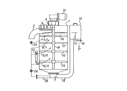
Figl is a schematic sectional view of the present reactor;

Eig~ is a schematic horizontal cross-section of Fig. l; and

Fi~ is an outer side view of the reactor of Fig. 1.


~ CA 0212670~ 1998-03-18


_ -- 3 --
Referring to the drawings, the present reactor includes a tank 1 within which, in an upper
portion thereof, there is located a main inlet duct 2 for a liquid to be purified, which is
introduced mixed with a gas or air sucked in through a duct 3 inserted into the inlet duct 2.
The foam formed by bubbles enclosing the impurities, e.g. ink contained in the liquid
introduced in the reactor, is removed by a rotating skimmer blade 4, which directs the foam
through an outlet duct 5. The skimmer blade 4 is cleaned by water jets 6 located above the
blade.

In the meanwhile, the purified liquid flows down through an outlet 7 located at the center of
a lower portion of the tank 1.

The tank 1 has inlet ducts 8, 9, 10 at different heights, as it can be seen in Fig. 3, through
simultaneously flows the purified liquid discharged through outlet 7. Gas or air is sucked
in through ducts 11, 12 and 13, respectively, co~ lu~licating with the liquid inlet ducts 8, 9,
and 10.

A portion of the purified liquid flowing out through outlet 7 is directed upwards, as indicated
by arrow 7A, towards a container 14, which is provided with an internal wall 15, along
which the purified liquid flows out through a drain 16, as indicated by arrow 17.
The tank 1 includes therein a rotating shaft 18 connected to a motor 19 for its rotation. The
shaft 18 is provided with blades 20, 21, 22, 23 positioned at different tank heights forming
washing beds, within which the liquid together with air or gas is introduced, as described
above.
The blades 20 - 23 increase in height from the top to the bottom of the tank 1, and have the
function of breaking up the gas-liquid-fiber phase, in the case of paper ~ lules, while their
different height is due to the fact that the speed of the downflowing liquid increases when
moving downwards, i.e. towards the bottom of tank 1. Also, the blades 20 - 23 are spirally
curved, with a concavity facing the direction of rotation ofthe shaft 18, as indicated by arrow

CA 0212670S 1998-03-18


_ - 4 -
24. Moreover, the blade rotation speed can be changed by means of a speed regulator, in
order to achieve a control of the chemical-physical reactions inside the reactor.

As is schematically shown in Fig. 1, the main inlet 2 of the liquid mixed with the gas or air
S is controlled by a valve 25, while the inlets 8 - 11, 9 - 12, 10 - 13 for the purified liquid and
gas or air are controlled by a valve 26.

The operation of the above-described reactor, and consequently the method for removing
impurities from the liquid, include the steps of introducing the liquid mixed with air or gas
into the upper portion of tank 1, further introducing the purified liquid with air or gas
simultaneously and continuously at different heights of tank 1 in the various washing beds,
the purified liquid flowing as indicated arrow by 7A and 7B from the outlet 7 of the tank 1,
and releasing a portion of the purified liquid as accepted liquid through the drain 16.
Furthermore, the stirring of the liquid by means of the blades 20, 21, 22, 23 increases when
moving down from the upper portion to the lower portion of tank 1, according to the
different blade height, as described above, and the liquid is simultaneously pushed towards
the central area of tank 1 by the particular spiral shape of blades 20, 21, 22, 23 in order to
effect the washing of the liquid with air at each horizontal section of the tank.


Representative Drawing
A single figure which represents the drawing illustrating the invention.
Administrative Status

For a clearer understanding of the status of the application/patent presented on this page, the site Disclaimer , as well as the definitions for Patent , Administrative Status , Maintenance Fee  and Payment History  should be consulted.

Administrative Status

Title Date
Forecasted Issue Date 1998-11-03
(22) Filed 1994-06-24
Examination Requested 1994-10-24
(41) Open to Public Inspection 1995-01-06
(45) Issued 1998-11-03
Deemed Expired 2000-06-27

Abandonment History

There is no abandonment history.

Payment History

Fee Type Anniversary Year Due Date Amount Paid Paid Date
Application Fee $0.00 1994-06-24
Registration of a document - section 124 $0.00 1995-09-21
Maintenance Fee - Application - New Act 2 1996-06-24 $50.00 1996-06-12
Maintenance Fee - Application - New Act 3 1997-06-24 $50.00 1997-06-13
Maintenance Fee - Application - New Act 4 1998-06-24 $50.00 1998-06-01
Final Fee $150.00 1998-06-05
Owners on Record

Note: Records showing the ownership history in alphabetical order.

Current Owners on Record
COMER S.P.A.
Past Owners on Record
FLAVIO, MAGARAGGIA
Past Owners that do not appear in the "Owners on Record" listing will appear in other documentation within the application.
Documents

To view selected files, please enter reCAPTCHA code :


To view images, click a link in the Document Description column. To download the documents, select one or more checkboxes in the first column and then click the "Download Selected in PDF format (Zip Archive)" or the "Download Selected as Single PDF" button.

List of published and non-published patent-specific documents on the CPD .

If you have any difficulty accessing content, you can call the Client Service Centre at 1-866-997-1936 or send them an e-mail at CIPO Client Service Centre.


Document
Description 
Date
(yyyy-mm-dd) 
Number of pages   Size of Image (KB) 
Representative Drawing 1998-10-19 1 8
Cover Page 1998-10-19 1 46
Abstract 1995-06-08 1 50
Cover Page 1995-06-08 1 38
Claims 1995-06-08 2 136
Drawings 1995-06-08 1 43
Description 1995-06-08 4 254
Abstract 1998-03-18 1 16
Description 1998-03-18 4 166
Claims 1998-03-18 4 119
Correspondence 1998-06-05 1 38
Fees 1997-06-13 1 39
Fees 1998-06-01 1 38
Prosecution Correspondence 1997-02-24 3 62
Examiner Requisition 1997-06-17 1 75
Prosecution Correspondence 1997-10-22 3 78
Office Letter 1994-11-30 1 59
Prosecution Correspondence 1994-10-24 1 31
Fees 1996-06-12 1 40