Note: Descriptions are shown in the official language in which they were submitted.
` -`` 21270~
CR088 REF~REN~ ~0 RB~AT~D APP~ICATION8
The present application claims the right of foreign
priority with respect to European Application No. EP 93 111
487.0 filed in the European Patent Office on July 16, 1993,
the disclosure of which is incorporated herein by reference.
BACRGRO~ND OF ~HE INVENTION
The invention relates to an espresso machine having a
brewing head located on its underside, into which a strainer
holder having a handle can be inserted from below with a
strainer. The strainer holder can be locked to or released
from the brewing head by means of a pivoting movement of the
strainer holder around the axis of the brewing head. Locking
and release are conventionally ef~ected by way of a bayonet
catch. For this purpose at least two lugs are provided at
the upper edge of the strainer holder and are inserted into
corresponding counterslots on the inside lower edge of the
brewing head by means of a vertically upward movement when
the strainer holder is coupled to the brewing head. The
strainer holder is thereafter locked with the brewing head by
means of a rotation of the str~iner holder. A sealed
connection between the brewing head, the strainer, the
strainer holder is thereby produced on a screw-shaped,
slanted plane.
- 2 -
' '
! ~ ~ 2 1 2 7 0 0 4
., .
The procedure of inserting the lugs into the slots
cannot be seen; therefore, practice is required to be able to
bring the strainer holder into the correct position without
tipping and an extensive loss of time.
8~MMARY OF ~B IN~BNTION
It is an object of the invention to provide an espresso
machine having the features mentioned at the outset and in
I which there is provided a structurally simple mechanism for
I ensuring that the correct position in which the strainer
holder is to be inserted into the brewing head from below can
be found easily and quickly.
The above and other objects are accomplished in the
context of an espresso machine having an underside provided
with a brewing head into which a strainer holder having a
lS handle can be inserted from below with a strainer inserted in -~
the holder, wherein the brewing head has slots and the
stralner holder includes corresponding lugs that fit through
: the~slots so that the strainer holder can be released from or :~
locked to the brewing h~ad by a pivoting movement of the
strainer holder around an axis of the brewing head which
places the lugs in or out of alignment with the slots,
resp~ctively, wherein according to the invention there is -~-
additionally provided a positioning ring h~ving a top end ;;
rotatably secured to the brewing head, a bottom end and a
_ 3 _
27aa~
cutout that is open toward the bottom end for recei~ing the
handle of the strainer holder; and means cooperating between
the positioning ring and the brewing head for locating the
positioning ring in an lnitial position so that when the
cutout in the positioning ring receives the handle of the
strainer holder, the strainer holder can be raised and
inserted into the brewing head with the lugs on the strainer
holder in alignment with the slots in the brewing head.
As a result of the invention, if it is desired to insert
the strainer holder into the brewing head of the espresso
machine, it need only be ensured that the positioning ring be
located in the initial position in which the strainer holder
can be inserted into the brewing head. The strainer holder
is then inserted from below into the brewing head in the
angular position in which the handle of the strainer holder
fits into the cutout of the positioning ring which is already
in the correct insertion position for the strainer holder.
The strainer holder is then moved upwardly, during which the
positioning ring is also moved upwardly, or remains in the
same place, and the correct position for locking the bayonet
catch is then found without further attempts.
There are numerous embodiments for the locating
mechanism which locates the initial position of the
positioning ring. One of these embodiments is characterized
in that the mechanism is configured as a latch, for example -~`
- 4 -
2:~27~
as a spring-loaded ball or the like provided on ona of the
two parts and which locks in a corresponding recess on the
other part in the initial position. Because of this, when
the positioning ring is rotated back into the initial
position there is an indication of when and in which angular
position the initial position is reached.
Another and likewise preferred embodiment of the
locating mechanism is characterized in that the mechanism has
a restoring spring that seeks to rotate the strainer holder
against a stop marking the initial position. In the process,
the restoration of the positioning ring into the initial
position is supported by the spring force, and the stop marks
the mentioned initial position.
Another, particularly structurally simple embodiment of
this locating mechanism is characterized by the provision of
: a visual display such as a marking on the brewing head which
aligns with another marking on the positioning ring when the
positioning ring is in the initial position. In this case ~i-
one need only ensure that two marks are opposite one another
to ensure that the initial position is reached. : ;
The cutout already provided on the positioning ring, :~
opposite which a corresponding mar~ing i5 located on the
brewing head or on the espresso machine itself in the initial
position of the positioning ring, can be used for the marking
2S on the positioning ring.
- 5 -
2~oo~
It is additionally pointed out that, due to space
constraints, the positioning ring is rotatably secured to the
outside of the brewing head. The positioning ring is
captively held, for example by a pin on one of the parts,
which pin extends into a corresponding groove on the other
part, or also by means of an annular shoulder on the
positioning ring that overlaps a corresponding shoulder on
the brewing head.
~he invention is described in detail below in
conjunction with the accompanying drawings by reference to a
preferred embodiment.
BRIEF DESCRIPTION OF T~I13 DR~lirIl~GS ~ :;
Figure 1 is a schematic side view, in partial section,
of components of an espresso machine according to the
~ 15 invention, the strainer holder being shown in an initial
- position for insertion into the brewing head from below the
brewing head.
Figure 2 is a view in the direction of arrow A of Figure
Figure 3 i5 a sectional view along line 3-3 of Figure 1.
~ ., ~ . .. ;.. ~.. I.. .. ,, . r -.... . . .. ; . . : .
` 2127V~
DE:q!AILED DE8CRIPq!ION OF T~113 P}~BFERRED EMBODI~
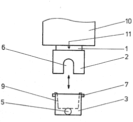
Referring to Figures 1 and 2, there is shown a lower
part of an espresso machine 10, on whose underside a brewing
head 1 is provided. on the inside, the brewing h~ad has
counterslots 8, which cooperate with lugs 7 on the top
outside o~ a strainer holder 3 in the manner of a bayonet
catch.
A coffee strainer 9 is ins~rted into strainer holder 3
in the usual manner. In addition, an outwardly-pointing
handle 5 is secured to the strainer holder.
In accordance with the invention there is provided an
insertion aid for the strainer holder which includes a
positioning ring 2 captively and rotatably positioned on the
outside of the brewing head 1. Positioning ring 2 has a
cutout 6 that is open toward its bottom end.
Figures 1 and 2 show that, to insert strainer holder 3
into the brewing head from below, the strainer holder is
disposed such that it extends from below with its handle 5
into cutout 6 of positioning ring 2. Suitable measures, as
discussed b~low, are previously taken to ensure that the
positioning ring is in the initial position prior to the
strainer holder being inserted from below into the brewing
head. The strainer holder (with or without the positioning
ring) can now be moved upwardly, so that the lugs 7 extend
into counterslots 8. Thereafter the strainer holder is
- 7 -
"~, .,,. . ~. , . . ., .,, . . , :,.... ., ,.,, . ,, ., . :,. ....
~ 2~270~
rotated, thus locking the strainer holder on the brewing
head.
Releasing the strainer holder from the brewing head is
effected accordingly with a reverse order of the movements;
in this instance, it is also ensured that the positioning
ring reassumes its initial angular position shown in the
drawings.
To ensure that the positioning ring assumes this initial
position, a latch can be provided as shown in Figure 3. In
the embodiment of Figure 3, the latch comprises a spring-
loaded ball 4 disposed on the positioning ring and extending
into a corresponding recess on the brewing head when the
positioning ring is in the initial position. O~ course, the
spring-loaded ball may be disposed on the brewing head and
the recess on the positioning to obtain the same effect.
Alternatively, a restoring spring (not shown), can bP
provided which ensures that the positioning ring reassumes
its initial position. Such a restoring spring seeks to
rotate the strainer holder against a stop that marks the
initial position of the positioning ring.
In an even simpler embodiment, in the initial position a
marking 11 on the brewing head or on the machine is located
opposite cutout 6, by means of which a visual display for the
initial position is created.
A pluxality of these locating mechanisms can also be
- 8 -
:` 2127~
provided, for example marking 11 combined with latch 4 or the
restoring spring.
Whien the bayonet catch is closed, positioning ring 2 is
thus co-rotated, and during opening it is rotated ~ack into
the initial position. The restoring spring or latch 4 causes
the positioning ring to always remain in the initial position
(zero position) when the strainer holder has been removed
until the strainer holder can be reinserted into the brewing
head.
:
_ ~ _
~ 2127~0~
It will be understood that the above description of the
present invention is susceptible to various modifications,
changes and adaptations, and the same are intended to be
comprehended within the meaning and range of equivalents of
the appended claims.
~:
-- 10 --
:i,.: ,.. , , . , : . . - , . . .:., " . : . ~ .