Note: Descriptions are shown in the official language in which they were submitted.
21 2 7 ~ 4 ~
1AIR BAG A5SEMaLY MOUNT
2B~CRGROUND OF THE INVENTION
3FIELD OF THE INVENTION
4The present invention generally pertains to an air bag
assembly and, more particularly, to connectors for removably
6 mounting an air bag assembly.
7 DE9CRIPTION OF THE RELATED ART
8 Air bag assemblies have been developed to be modular in
9 design to speed installation of the assembly within a vehicle.
Air bag assemblies or modules typically include an inflator,
11 an inflatable air bag or cushion, and a cover member. The
12 cover member is separable to allow the cushion to escape
13 therethrough during inflation. The entire assembly or module
14 is typically immovably bolked in place. Although bolting
satisfactorily attaches the air bag assembly to the underlying
16 support structure, it takes a considerable amount of time
17 during assembly, and renders the mounted assembly difficult
18 to un-attach and remove. Therefore, there exists a need in
19 the art for an improved connector to rigidly but removably
mount an air bag assembly within a vehicle.
21 Rigidly or immovably mounting the modular air bag
22 assembly is acceptable in most applications. However, in
23 driver's-side air bag assemblies, the cover member of the
24 module occupies the center portion of the steering wheel, and
thereby displaces the horn actuator mechanism from its
26 traditional center position on the steering wheel. Separate,
27 relatively small buttons or pads spaced from the center of the
28 steering wheel are added to provide the horn actuation
29 feature.
~'
~.
, . ... . . .
. : . .. .
, ".,
-22-l 2 ~
1 Naturally, it is desirable for the driver to sound the
2 horn as quickly as possible. However, since the horn actuator
3 pads are relatively small and displaced from the center of the
4 steering wheel, it takes time for the driver to locate the
pads, and renders the horn actuators used on these steering
6 wheels somewhat less desirable and effective than those
7 provided by prior steering wheels. Therefore, some consumers
8 may perceive that cars having steering wheels which
9 incorporate rigidly or immovably mounted air bags are less
desirable, at least in this respect, than cars which do not
11 incorporate such air bags into the steering wheel.
12 In response to the limitations of the fixedly-mounted air
13 bag modules and small horn actuation pads discussed above, it
14 has been proposed to mount the air bag module such that it is
movable relative to the steering wheel. Movably mounting the
16 air bag module allows it to incorporate a horn-actuation
17 feature and thereby return the horn actuator to its customary
18 and appropriate location in the center of the steering wheel.
19 Although this method of mounting the air bag module
eliminates the problems associated with horn actuator
21 placement, the mounting connectors currently used to movably
22 mount the module to the steering wheel are of the ball-detente
23 type, and are expensive and difficult to manufacture. As
24 such, the problems associated with the known connectors for
movably mounting the modules actually encourage manufacturers
26 to continue to fixedly or immovably mount the air bag modules
27 to the steering wheel.
28 Hence, there exists a need in the art for a simple and
29 inexpensive mounting connector which removably attaches the
air bag module to the steering wheel and allows the module to
31 move relative to the steering wheel.
.... . , ,f ,
:~ ~ . , :; :, ,
~ .: :
2 1 2 ~ ~ 4 ~
1 ~UMMARY OF THE INVENTION
2 The present inventibn provides an improved air bag
3 assembly mounting connector. A first embodiment of the
4 present invention is directed toward a mounting connector for
an air bag module which allows the module to move relatively
6 toward and away from a steering wheel of an automobile. The
7 connector removably attaches the air bag module to the
8 steering wheel and cooperates with a mounting plate provided
9 by the steering wheel to define a horn switch. A second
embodiment of the present invention is directed toward a
11 mounting connector which rigidly but removably attaches the
12 air bag module to a mounting plate.
13 In accordance with the first embodiment of the present
14 invention, a steering wheel including an air bag module
a~5embly is provided. The module assembly includes a cover
16 member, an inflator operable to inflate a cushion, a base
17 plate, means ~or attaching the cushion to the base plate, and
18 a series of mounting connectors for removably attaching the
19 module to a mounting plate provided by the steering wheel.
The cover member, which is separable upon inflation of the
21 inflatable cushion to permit the cushion to escape or project
22 therefrom, overlies the inflatable cushion and the base plate
23 and defines an exterior center portion of the steering wheel.
24 The inflator attaches to the base plate and extends through
the base plate and into the inflatable cushion.
26 In further accordance with the first embodiment of the
27 present invention, the mounting connectors have first and
28 second members and means for biasing the first and second
29 members relatively away from each other. The first member
telescopingly receives the second member and includes means
31 for retaining at least some oE the second member therewithin.
32 The first member has a distal end which attaches the mounting
33 connector to the base plate. The second member includes a
34 series of resiliently deformable arms which extend away from
the first member and removably attach to the mounting plate.
... '. : ' .. : ' .','' . ' ' . ' ' . ' ,.,' .. : ' " . ::: . . ,.. i, ,i,.,' , ' .. , .. , . ~ ' '
~4~ 2 12~ a ~
1 In further accordance with the first embodiment of the
2 present invention, the mounting plate defines a first horn
3 switch contact and the first member defines a second horn
4 switch contact. The biasing means normally maintains the
first and second contacts relatively away from each other.
6 The biasing means can be overcome by inward force upon the
7 cover member above a predetermined threshold, causing the
8 first member to engage the mounting plate and thereby actuate
9 the horn.
The mounting connectors according to the first embodiment
11 snap-fit the air bag module to the mounting plate, which eases
12 and speeds assembly of the steering wheel, while allowing the
13 center portion of the steering wheel to provide a horn-
14 actuating function as was customary prior to the development
of air bags. The connectors are removably mounted or attached
16 to the mounting plate, and thereby allow the air bag module
17 to be removed or withdrawn from the steering wheel for
18 maintenance and service.
19 In accordance with a second embodiment of the present
invention a mounting connector for rigidly but removably
, 21 attaching an air bag module assembly to a mounting plate is
22 provided. The mounting connector is designed to attach the
23 module to a steering wheel, dashboard, seat back, head rest,
24 or any other location in a passenger compartment for an
, 25 automobile, air plane, truck, boat, bus or the like where an
26 air bag-type passive occupant restraint is desired.
27 In further accordance with the second embodiment of the
28 present invention, the mounting connector includes an enlarged
29 head and a series of resiliently deformable arms. Each of the
arm~ have an enlarged retaining distal portion and a proximal
31 mounting portlon. The retaining portion removably attaches
32 the module to a mounting plate while the mounting portion
~e 33 attaches the connector to a base plate provided by the module.
34 In further accordance with the second embodiment of the
present invention, the mounting portion provides upper and
36 lower co-axial cylindrical surfaces adjacent a shoulder
~,¢'
~5~ 2~%7~
1 surface provided by the enlarged head. The upper cylindrical
2 surface is adjacent the retaining portion of the arm. An
3 interference fit between the lower cylindrical surface and the
4 base plate retains the connector on the module.
BRIEF DE8CRIPTION OF T~E DRAWING FIGURE~
6 These and further features of the present invention
7 will be apparent with reference to the following description
8 and drawings, wherein:
9 FIG. 1 is an exploded perspective view of an air bag
module incorporating a series of mounting connectors in
11 accordance with a first embodiment of the present invention;
12 FIG. 2 is an exploded perspective view of a base plate
13 and the mounting connectors in accordance with the first
14 embodiment of the present invention;
FIG. 3 is an elevational view, in cross section, of the
16 mounting connector, base plate, and a mounting plate in a
17 normal or at-rest condition in accordance with the first
18 embodiment of the present invention;
19 FIG. 4 is an elevational view, in cross section, of the
mounting connector, base plate, and mounting plate in an
21 inward or horn actuating position, in accordance with the
22 first embodiment of the present invention;
23 FIG. 5 is an exploded perspective view of the mounting
24 connector according to the first embodiment of the present
invention;
26 FIG. 6 is an exploded perspective view of the air bag
27 module and steering whee] in accordance with the first
28 embodiment of the present invention;
29 FIG. 7 i5 front elevational view of the mounting
connector in accordance with a second embodiment of the
31 present invention, with a mounting plate and base plate shown
32 in phantom;
;
'
2~2704~
1 FIG. 8 is an enlarged elevational view, partly in cross
2 section, of a portion of the mounting connector in accordance
3 with the second embodiment of the present invention; and,
4 FIG. 9 is a top plan view of the mounting connector
illustrated in FIG. 7.
6 DETAILED DE8CRIPTION OF THE PREFERRED EMBODIMENTS
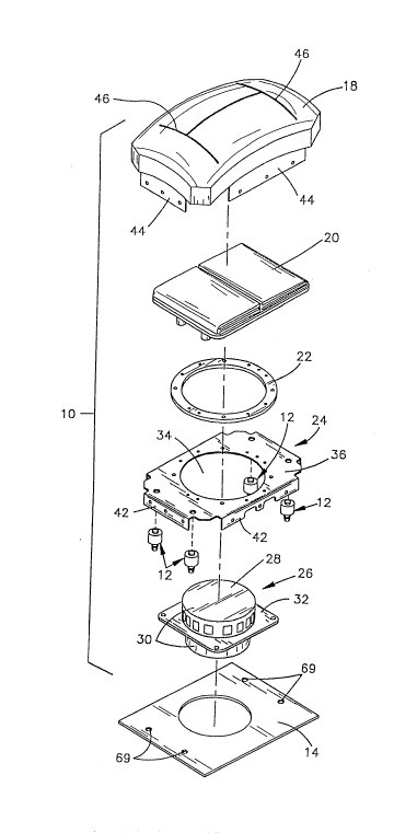
7 With reference to FIGS. 1-6, an air bag module 10
8 incorporating mounting connectors 12 in accordance with a
9 first embodiment of the present invention is shown. The air
bag module 10 is designed to removably mount to a mounting
11 plate 14 provided by a steering wheel 16 (FIG. 6) and
12 includes, in addition to the mounting connectors 12, a cover
13 member 18, an inflatable cushion 20, a cushion retainer 22,
14 a base plate 24, and an inflator 26 (FIG. 1).
~he inflator 26 includes a housing 28 and an inflator
16 module (not shown). The inflator module is preferably of the
17 sodium azide-type, and produces a large volume of gas to
18 quickly inflate the cushion. As shown best in FIG. 1, the
19 inflator housing 28 includes a pair of oppositely-directed
cylindrical portions 30 and a thin outwardly extending skirt
21 32. The cylindrical portions 30 define a cavity for receipt
22 of the inflator module. Conventional fasteners attach the
23 skirt 32 to the base plate 24 while one of the cylindrical
24 portions 30 extends through a central hole 34 in the base
plate 24 and into the cushion 20, as is generally well known
26 in the art.
27 The base plate 2~ provides a generally planar rectangular
28 surface 36 in which i6 formed the central hole 34. The
29 cushion 20 includes a circular opening or mouth (not shown)
which overlies the central hole 34 and is secured to the base
31 plate 24 by the cushion retainer 22. More specifically, the
32 cushion fabric adjacent the circular mouth is trapped or
33 sandwiched between the retainer 22 and the baseplate 24j the
~,. . , , . : ...... ; .: ~ ,,, : ,: .... . . .
~7~ 2127~
1 retainer 22 and cushion 20 thereafter being riveted or
2 otherwise permanently attached to the base plate 24.
3 Encircling the central hole 34 in the base plate is an
4 array of relatively smaller sized mounting holes 38, as
illustrated in FIGS. 1 and 2. Some of the mounting holes are
6 provided to attach the cushion 20 and cushion retainer 22 to
7 the base plate 24 while others of the mounting holes are
8 provided to attach the inflator housing 28 to the base plate
9 24. At each corner of the rectangular surface 36 is provided
an opening 40 which receives one of the mounting connectors
11 12.
12 Downwardly-directed flanges 42 extend from the four edges
13 of the base plate 24 and attach to associated panels 44
14 provided by the cover member 18. The cover member 18, which
defines a top surface of the module 10, is separable along a
16 series of seams 46 to allow the inflatable cushion 20 to
17 escape and project there-through upon inflation. A bottom
18 surface of the air bag module 10 is defined by the inflator
19 housing 28 and the base plate 24.
The mounting connectors 12 project downwardly from the
21 baseplate 24 and include three component parts: an outer or
22 first member 48, an inner or second member 50, and a coil
23 spring 52 which biases or urges the inner member 50 relatively
24 away from or telescopingly out of the outer member 48.
The outer member 48 is electrically conductive and has
26 a generally cylindrical main body portion 54 and an upstanding
27 cylindrical neck 56. The neck 56 extends through the opening
28 40 in the base plate 24, a terminal portion 58 of the neck 56
29 projecting above the base plate being radially outwardly
deformed or bent over to attach the mounting connector 12 to
31 the base plate 24, as shown best in FIGS. 3 and 4. The.outer
32 member 48 can be made of any suitable conductive material,
33 such as cold rolled steel.
34 The main body portion 54 of the outer member 48 receives
the coil spring 52 and a proximal end 60 of the inner member
36 50. The inner member 50 telescopingly extends from the outer
- -8- 2~27~
1 member 48 under the influence of the coil spring 52, the
2 proximal end 60 being maintained within the main body portion
3 54 of the outer member 48 by a radially in-turned annular lip
4 62 provided by the main body portion.
The inner member 50 is electrically insulati~e and
6 includes, in addition to the proximal end 60, a distal end 64
7 which telescopingly extends from a circular opening defined
8 by the annular lip 62 of the outer member 48. The proximal
9 end 60 of the inner member 50 is bowl-shaped, and opens toward
the neck 56 of the outer member 48 and cooperates with the
11 main body portion 54 to receive the coil spring 52.
12 Preferably, the inner member 50 is formed of a dimensionally
13 stable, heat and corrosion resistive material, such as 6/6
14 Nylon.
The distal end 64 of the inner member includes a
16 transition portion 66 and a series of spaced-apart, outwardly-
17 extending resilient arms 6~. The transition portion 66 merges
18 with a bottom of the bowl-shaped proximal end 60 and is
19 ~dapted and sized to extend through the circular opening in
the outer member 48 defined by the annular lip 62. The
21 resilient arms 68 project from the transition portion 66 and
22 are inwardly deformable to allow them to be removably inserted
23 into a hole 69 in the mounting plate 14 and thereby releasably
24 attach the connector 12 and, hence the module 10, to the
mounting plate 14.
26 A circumferential or annular groove 70 is provided by the
27 distal end 64 of the inner member 50 adjacent the union of the
28 transition portion 66 and the resilient arms 68. The groove
29 70 is discontinuous, being interrupted by the spaces between
the arms 68, and limited or bounded by upper and lower
31 shoulder surfaces 72, 7~. The groove 70 receives the mounting
32 plate 1~ and the upper and lower shoulder surface6 72, 7~
33 engage opposite sides of the mounting plate to attach the
34 connectors 12 and, thus, the module 10, to the steering wheel
16. More particularly, the upper shoulder surface 72 limits
36 insertion of the connector 12 into the hole 69, while the
2~27~
1 lower shoulder surface 74 releasably prevents removal of the
2 connector 16 from the hole 69 in the mounting plate 14.
3 Assembly of the mounting connectors 12 of the first
4 embodiment of the present invention is a relatively simple
process. The coil spring 52 is inserted into the cylindrical
6 main body portion 54 of the outer member 48, then the bowl-
7 shaped proximal end 60 of the inner member 50 is inserted into
8 the main body portion 54 such that the coil spring 52 is
9 received by and extends into the bowl-shaped proximal end 60.
Thereafter, a machine (not shown) forces the inner member 50
11 into the main body portion 54 while inwardly deforming a
12 terminal edge of the outer member 48 to form the annular lip
13 62.
14 As so deformed, the annular lip 62 retains the inner
member 50 within the outer member 48 while allowing the inner
16 member 50 to move in a telescoping fashion relative to the
17 outer member 48. The spring 52 biases the inner member to its
18 outwardmost or at-rest position shown in FIG. 3 wherein the
19 bowl-shaped portion of the inner member 50 abuts the annular
lip 62 and the transition portion 66 and resilient arms 68
21 project from the outer member 48.- Once the mounting connector
22 12 is assembled, it is attached to the base plate 24 by
23 lnserting the neck 56 of the outer member through one of the
24 openings 40 in the base plate, and radially outwardly
deforming the terminal portion 58 of the neck 56.
26 With the mounting connectors 12 attached to the base
27 plate 24, the cushion 20 and cushion retainer 22 are attached,
28 by rivets or the like, to the base plate 24, as discussed
29 hereinbefore. Thereafter, the panels 44 of the cover member
18 are attached to the flanges 42 of the base plate 24 to
31 complete assembly of the module.
32 With the module 10 80 assembled, and the mounting
33 connectors 12 projecting downwardly from the base plate 2~,
34 the air bag module 10 can be snap-fittingly mounted to the
steering wheel 16. The resilient arms 68 of the inner member
36 50 are aligned with the holes 69 provided by the mounting
-lo- 2~27a~
1 plate 14, and pushed toward the mounting plate 14. The arms
2 68 are cammed or deformed radially inwardly as they pass
3 through the holes 69. Once through the holes 69, the arms 68 "
4 snap outwardly, receiving the mounting plate 14 within the
5 annular groove 70 (i.e., between the shoulder surfaces 72, 74)
6 and generally preventing further movement of the inner member
7 50 relative to the mounting plate 14. i .
8 With reference to FIGS. 3 and 4, the operation of the
9 mounting connectors 12 of the first embodiment as a portion
10 of the horn actuator mechanism is shown. The mounting
11 connectors 12 space the base plate 24 from the mounting plate
12 14, and provide a contact for a horn actuation switch. More
13 spe,cifically, the bias of the coil spring 52 maintains the
14 outer member 48 of the mounting connector 12 a distance from
15 the mounting plate 24, while the mounting plate 14 serves as
16 the first contact of the horn actuation switch and the outer
17 member's annular lip 62 serves as the second horn switch
18 contact.
19 The annular lip 62 is usually maintained a short distance
20 from the mounting plate 14 due to the bias of the coil spring
21 52 (FIG. 3), as discussed previously. When sufficient force
22 is exerted upon the cover member 18 to overcome the spring
23 bias, the entire module 10, with the exception of the inner
24 member 50 of the mounting connector 12, moves toward the
25 mounting plate 24. The movement of the module 10 is limited
26 by engagement of the annular lip 62 with the mounting plate
27 24, which closes the horn actuation switch (FIG. 4) and sounds
28 the horn. Placement of the mounting connectors 12 at the four
29 corners of the module, 10 securely attaches the module 10 to
30 the mounting plate 1~, while assuring that inwardly directed
31 pressure at any location on the cover member 18 will actuate
32 the horn.
33 The module 10 is disengaged or unattached from the
34 mounting plate by radially inwardly deforming the resilient
35 arms 68 to free the lower shoulder surfaces 74 from engagement
36 with the mounting plate 14. A tool (not shown) can be
.,
.
'"' ' . "~' `
-11- 2~ 27~J~
1 provided to simultaneously disengage all of the mounting
2 connectors 12 from the mounting plate 14. Thereafter, the
3 module 10 is simply pulled away from the mounting plate 14 to
4 complete removal of the module from the steering wheel 16.
With reference to FIGS. 7-9, a mounting connector 110 in
6 accordance with a second embodiment of the present invention
7 is illustrated. The mounting connector 110, which is
8 preferably formed of reinforced nylon, is adapted to rigidly
9 ~ount a base plate 24 of an air bag module assembly 10 to a
mounting plate 14. The air bag module assembly 10 and
11 mounting plate 14 are generally identical to those illustrated
12 in FIGS. 1-6, with the exception of the present embodiment of
13 the mounting connector 110 and any modifications to the plates
14 14, 24 necessary to allow the base plate 24 and mounting plate
14 to engage in a face-to-face manner, and will therefore not
16 be ~urther dlscussed hereinafter.
17 The mounting connector 110 includes an enlarged head 112
18 and a series of resiliently deformable arms 114. The head
19 112, which includes a hollow or bowl-shaped lower end,
provides a generally planar shoulder surface 116 from which
21 the arms 114 project. The shoulder surface 116 acts as a stop
22 to limit insertion of the mounting connector 110 into the base
23 plate 24 and engages an inner surface 24a of the base plate.
24 The arms 114, which are spaced-apart by notches or slots 118,
include a distal retaining portion 120 and a proximal mounting
26 portion 122.
27 As illustrated best in FIG. 8, the retaining portion 120
28 of each arm 114 includes an outer camming surface 124 and an
29 engaging surface 126. The camming surface 124 is adapted to
slidably engage the base plate 24 and the mounting plate 14,
31 causing the arms 114 to deform radially inward, and allowing
32 insertlon o~ the mounting connector 110 into the plates 14,
33 24. The camming surface 124 forms an angle A with respect to
34 vertical and, preferably, the angle A is equal to about 8.
The engaging surface 126 is adapted to engage an outer surface
36 14a of the mounting plate 14 and releasably prevent removal
-12- ~ ~ 2 7 ~ 3
1 of the mounting connector llo therefrom. The engaging surface
2 126 is curved and ramps upwardly as it moves radially inward,
3 and forms an angle B with respect to the shoulder surface 116.
4 The angle B is preferably equal to about 5.
The mounting portion 122 of each arm 114 includes upper
6 and lower co-axial cylindrical surfaces 130, 132. The upper
7 cylindrical surface 130 merges with the engaging surface 126
8 and is slightly smaller in diameter than the lower cylindrical
9 surface 132. The lower cylindrical surface 132 merges with
the shoulder surface 116 of the enlarged head 112. The upper
11 and lower cylindrical surfaces 130, 132 are interconnected by
12 an arcuate ramping or camming surface 134 which provides a
13 gradual transition from the smaller diameter upper cylindrical
14 surface 130 to the larger diameter lower cylindrical surface
132. ~he ramping surface 134 preferably forms an angle C of
16 about ~5 with respect to the plane~ defined by the shoulder
17 surface 116.
18 The notches 118 separating the arms 114 result in
19 discontinuity in the cylindrical surfaces 130, 132, the
ramping surface 134, and the shoulder surface 116. The
21 notches 118 extend into the enlarged head 112 a short distance
22 to help promote elastic bending of the arms 114. Preferably,
23 the notches 118 make an angle D with respect to a vertical
24 axis and, most preferably, the angle D is equal to about 5.
Installation and use of the mounting connector 110
26 according to the second embodiment of the present invention
27 will hereafter be described with reference to the foregoing
28 description and drawings.
29 Prior to assembly of the air bag module 10, the retaining
portion 120 of the mounting connector 110 is aligned with a
31 mounting hole 40 provided by the base plate 2~. Pushing force
32 on the enlarged head 112 moves the,retaining portion 120 of
33 the arms 11~ through the hole 40, causing the camming surface
34 124 to engage the base plate 24 and force the arms 114 to
resiliently deform radially inward. once the retaining
36 portions 120 of the arms 114 pass through the hole 40, the
:: . ~
` -13- 2~7 ~ ~
1 arms 114 snap radially outwardly to their original or at-rest
2 position.
3 Further pushing force on the enlarged head 112 causes the
4 upper cylindrical surface 130 and the camming surface 134 to
pass through the hole 40. Thereafter, the edges of the base
Ç plate 24 surrounding the hole 40 engage the lower cylindrical
7 surface 132. The diameter of the lower cylindrical surface
8 132 is preferably sized to closely match the diameter of the
,9 hole 40 in the base plate 24 to provide an interference fit
between the lower cylindrical surface 132 and the base plate
11 24. The edges of the base plate 24 surrounding the holes 40
12 may be serrated, grooved, threaded, or otherwise shaped to
13 enhance frictional contact between the connector 110 and the
14 base plate 24. The interference or press-fit between the
mounting connectors 110 and the base plate 24 is the only
16 means required to attach the connector 110 to the base plate
17 24. Preferably, once inserted in the hole 40, the mounting
18 connector 110 will be capable of resisting at least 45N of
19 outwardly-directed force (i.e., force, tending to move the
mounting connector 110 out of the base plate 24). This
21 resistance to outward force is necessary because when the
22 module 10 is attached to the mounting plate 14 there is a
23 force tending to push the connectors 110 out of the holes 40,
24 as will be described more fully hereafter.
Depending upon the tolerances maintained during
26 manufacture of the base plate 24 and the mounting connector
27 110, a portion of the camming surface 134 adjacent the lower
28 cylindrical surface 132 may be deformed due to contact with
29 the base plate 24, especially if the edges surrounding the
holes 40 are not smooth. The camming surface 134 also acts
31 to center the connector 110 within the hole 40, which eases
32 and speeds assembly. Once the connectors 110 are attached to
33 the base plate 24, the remainder of the module 10 is assembled
34 as described in the foregoing first embodiment.
35The module 10 is attached to the mounting plate 14 by
36aligning the connectors 110 with the holes 69 in the mounting
;~ ,
.,
, , ,: . . , .: ,
-14- 2~ 2~
1 plate and pushing the module toward the mounting plate 14.
2 The camming surfaces 12~ of the retaining portions 120
3 slidably engage the mounting plate 14 adjacent the holes 69,
4 resiliently deforming the arms 114 and allowing the retaining
portion 120 to pass through the holes 69. Once the retaining
6 portions 120 pass through the holes 69, the arms 114
7 resiliently snap radially outward to their at-rest or normal
8 position. When the arms 114 are being pushed through the
9 holes 69, a force is created which tends to push the
connectors 110 away from the base plate, 24. This force is
11 counteracted by the interference fit between the connectors
12 110 and the base plate 24.
13 The engaging surface 126 contacts a top surface 14a of
14 the mounting plate 14. Forming the engaging surface 126 at
an angle relative to the plane defined by the shoulder surface
16 116 allows the retaining portion to compensate for
17 manufacturing tolerances in the mounting plate 14 and base
18 plate 24 thicknesses. For example, if the mounting plate 14
19 is slightly thicker than illustrated, the retaining portion
120 will rotate slightly inwardly, the angle B will be
21 slightly less, and the engaging surface 126 will remain in
22 contact with the top surface 14a of the mounting plate 14.
23 The angle B of the engaging surface 126 therefore
! 24 compensates for manufacturing tolerances while rigidly
~ 25 attaching the connector 110 to the mounting plate 14.
v, 26 Tolerance compensation provided hereby ensures that the module
, 27 10 will not vibrate due to a loose fit between the connector
! 28 110 and the mounting plate 14.
~ 29 The mounting connectors 110 firmly yet removably attach
;" 30 the module 10 to the mounting plate 14. The retaining portion
,,,j 31 120 ensures that the module 10 will not be inadvertently or
32 accidentally unattached from the mounting plate 14.
33 Preferably, the retaining portions 120 of the arms have a high
34 tension strength,- each connector 110 being capable of
35 withstanding at least about 7500N pulling force. ~'
~,, '1, ' ' . ' ' ""
~.. ; ., : ,, :,
j.t~
i,` . . . . .
-15- 2~27{~
1 The module 10 is disengaged or unattached from the
2 mounting plate 14 by radially inwardly deforming the resilient
3 arms 114 to free the engaging surfaces 126 from engagement
4 with the outer surface 14a of the mounting plate 14. A tool
(not shown) can be provided to simultaneously disengage all
6 of the mounting connectors 110 from the mounting plate 14.
7 Thereafter, the module lo is simply pulled away from the
8 mounting plate 14 to complete removal of the module from the
9 mounting plate 114.
While the preferred embodiments of the present invention
11 are shown and described herein, it is to be understood that
12 the same is not so limited but shall cover and include any and
13 all modifications thereof which fall within the purview of the
14 present invention as defined by the claims appended hereto.
For example, the term mounting plate as used herein is
16 intended to refer to any support structure to which the air
17 bag module is attached. Also, although the mounting
18 connectors according to the first embodiment are described as
19 being associated with a steering wheel, it should be clear
that these connectors can be employed to attach the air bag
21 module to any structure, such as a dashboard, head rest, or
22 seat back.
.,
t
~j :
''
;~'; .