Note: Descriptions are shown in the official language in which they were submitted.
21 27071
BLOWING APPARATUS, SUCTION PANEL THEREFOR
AND STRAIGHTENING GUIDE THEREFOR
BACKGROUND OF THE INVENTION
l. Field of the Invention
This invention relates to a blowing apparat~s whose
suction passage is not linear, to a suction panel thereof, and
to a straightening guide thereof.
2. Discussion of the Related Art
In some blowing apparatuses such as ventilating fans
and ventilating systems, the suction passage extending from the
suction port to the fan suction port of the blower is not
linear. That is, the suction- port is disposed at a position
out of the front of the suction port so that the inner
structure of, e.g., the blower cannot be seen from the suction
port. The suction port is generally formed at a suction panel
that constitutes the front of the blowing apparatus. The
suction panel itself tends to be flat in structure to improve
the design of the blowing apparatus.
Blowing apparatuses of this type are disclosed by,
e.g., Japanese Utility Model Unexamined Publications Nos. Hei
4-113843, Hei 2-538, and Sho 59-49827. Each of these
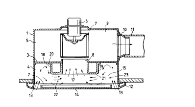
zo apparatuses has such a basic structure as shown in Figure 17.
In Figure 17, a main body frame 1 that is of a rectangular box
type with one open surface is divided into two sections, a
suction chamber 4 and a blower chamber 5, by an opening 2 and
2127071
a suction partition 3 that extends in parallel with the opening
2. A motor 6 is mounted substantially in the middle of a
surface of the main body frame 1 which is opposed to the
opening 2. A multiblade fan 7 is attached to the rotary shaft
of the motor 6. The multiblade fan 7 rotates inside the blower
chamber ~. Substantially in the middIe of the suction
partition 3 is a fan suction port 8, which is not only circular
so as to be coaxial with the multiblade fan 7 but also bell-
mouthed. The fan suction port 8 is open to the suction chamber
o 4. Further, a blowout port 10 communicating with a blowout
passage 9 is formed in one side of the blower chamber 5. A
piping member 11 installed in the ceiling is connected to the
blowout port 10. -
The main body frame 1 is fixed so that the opening 2 is15 generally flush with the ceiling surface of the ceiling plate.
A suction panel 12 is attached to the opening 2, which faces
the ceiling surface, by a fastening means such as a spring so
as to close the opening 2. The suction panel 12 has slit-like
suction ports 13 formed in the vicinity of the outer edge
portions thereof that do not confront the fan suction port 8.
The slit-like suction ports 13 communicate with the suction
chamber 4 and extend along the four sides or two opposing sides
of the suction panel 12. Therefore, the front of the fan
suction port 8 is concealed by a front panel portion 14 of the
suction panel 12 so as not to be seen from outside. The
suction chamber 4 is formed of a space enclosed by the rigid
2I27071
body surfaces including the inner peripheral surfaces of the
main body frame l, the suction partition 3, and the suction
panel 12, and constitutes a suction passage 15 that extends
from the suction ports 13 to the fan suction port 8 via the
suction chamber 4 in nonlinear form.
Since the main body frame 1 and the suction cnamber 4
usually must have an appropriate area as a suction passage or
blowout passage, the sectional area thereof is set to a value
about 3 to 6 times the opening area of the fan suction port 8.
0 If the height of the suction chamber 4 (H in Figure 17) is too
small, the suction chamber 4 is subjected to pressure losses
and cannot absorb the inertia of a rapid stream from the
suction ports 13, thus havin~ difficulty turning the stream
toward the fan suction port 8. Hence, the height is set to a
value at least about 30 to 60% the diameter of the fan suction
port 8. On the other hand, the area of opening of the suction
ports 13 is set to a value as small as possible so that design
requirements can be met. The area is set to a value
approximately equal to or up to twice the area of opening of
the fan suction port 8. Therefore, the suction passage 15
extending from the suction ports 13 to the fan suction port 8
via the suction chamber 4 expands suddenly at the suction
chamber 4 from the narrow suction ports 13, and then narrows
again at the fan suction port 8, making itself nonlinear.
Also, another type of blowing apparatus is disclosed in
Japanese Patent Unexamined Publication No. Hei 5-126378. As
2~ 27071
_
indicated by the chain line in Figure 17, an umbrella-like
guide member 16 made of a noise insulating material is provided
on the back of the suction panel 12, so that not only the
stream to the fan suction port 8 can be guided, but also fan
noise propagated from the fan suction port 8 to the front panel
portion 14 can be reduced.
A blowing apparatus having the similarly nonlinear
suction passage 15 from the suction ports 13 to the fan suction
port 8 via the suction chamber 4 is disclosed in Japanese
lo Utility Model Unexamined Publication No. Hei 1-125897. This
blowing apparatus is constructed, as shown in Figure 18, so
that the main body frame 1 is of a box type having no opening.
The suction port 13 that is connected to the piping member 11
is formed on a side opposite to the blowout port 10.
Therefore, there is no suction panel, and the suction chamber
4 is formed into an L-shaped space enclosed by the inner
peripheral and bottom surfaces of the main body frame 1 and the
outer surface of the blower chamber 5. The suction passage 15
suddenly expands at the wide suction chamber 4 from the narrow
zo suction port 13 and narrows again at the fan suction port 8,
similarly making itself nonlinear.
Any of the above-mentioned blowing apparatuses sucks
air from the suction port or ports 13 to the fan suction port
8 via the suction chamber 4 by the rotation of the motor 6. At
this time, the rapid stream introduced from the narrow suction
port or ports 13 is decelerated upon entrance into the suction
-- 4
A
2127071
chamber 4, having the inertial effect thereof lessened.
Therefore, the flow of the stream becomes dependent on the
sucking force produced at the fan suction port 8, leaving
itself sucked into the fan suction port 8.
In the conventional blowing apparati thus
constructed, the suction chamber 4 shown in Figure 17 expands
suddenly and, therefore, the stream introduced into the
suction chamber 4 is not decelerated uniformly, but flows
while picking up air within the suction chamber 4. As a
lo result, the direction of the stream is not steady, which
eventually makes the stream extremely disturbed as shown by
the arrows in Figure 17. Such disturbed stream is converged
at the fan suction port 8 within a short range in the floating
direction, leaving the stream running into the multiblade fan
7 in an unstraightened condition, thus, aggravating the
turbulence of the stream in the multiblade fan 7. This
results in large fan noise. Further, the umbrella-like guide
member 16 straightens the stream on the suction side to some
degree, but the straightened stream is such that only some
parts of the multiblade fan 7 can function, thus impairing
blowing efficiency. In addition, the level of noise
insulation is not more than what is implemented by the guide
member 16.
Because the suction chamber 4, including the blowout
passage 9, is enclosed by rigid body surfaces, repetitive
reflection of sound waves of noises echo between opposing
rigid body surfaces, causing a standing wave, which is a sound
2l27071
whose frequency is determined by the form and size of the
chamber, (i.e., resonance). Since the fan noise that becomes
a source for causing resonance is so large, as described
above, the resonance is also large. Figure 19 shows the
frequency spectra of the noise produced by the blowing
apparatus shown in Figure 17. A high-level acoustic resonance
is generated at 500 Hz and 1 kHz, and a low-level acoustic
resonance is generated between 2 and 3 kHz.
The above-mentioned problem is addressed likewise
in the blowing apparatus shown in Figure 18 in which the flow
passage of the suction chamber 4 is relatively long. However,
the blowing apparatus shown in Figure 18 is characterized in
that the suction chamber 4 has a right-angled corner and there
is only one suction port 13 which is unevenly distributed in
one direction with respect to the fan suction port 8. These
factors contribute to increasing the turbulence of the stream
- in the suction chamber 4 and aggravate the stream flowing into
the multiblade fan 7.
SUMMARY OF THE INVENTION
The present invention has been made to overcome the
above-mentioned conventional problems. Accordingly, an object
of the invention is to achieve noise reduction by
substantially decreasing the turbulence of a stream flowing
into a blower.
Another object of the invention is to decrease the
level of resonance without impairing blowing efficiency.
-- 6 --
212707t
Still another object of the invention is to reduce
noise of the blowing apparatus with a simple arrangement.
A first aspect of the invention is applied to a blowing
apparatus in which suction ports and a fan suction port open
toward a suction chamber enclosed by rigid body surfaces and in
which a suction passage formed of these three parts is arranged
in nonlinear form. In such a blowing apparatus, a
straightening guide is provided at an opening edge of the fan
suction port on the suction chamber side. The straightening
lo guide is of such a doughnut-like shape as to have a guide
passage at the center thereof with a projection toward the
suction chamber and an appropriate thickness in the radial
direction, the guide passage matching the fan suction port.
A second aspect of the invention is applied to a
blowing apparatus, wherein a constricting section formed of a
curved inner surface is provided in the middle of the guide
passage of the straightening guide according to the first
aspect of the invention, and the inner diameter of the guide
passage is gradually increased from the constricting section
toward the fan suction port.
A third aspect of the invention is applied to a blowing
apparatus, wherein the straightening guide according to the
first or second aspect of the invention is formed of a hollow
body; a noise absorbing member is filled in the hollow body;
and a back side of the noise absorbing member is caused to
2 1 2707 1
communicate with a blowout side of the blower by an air
introducing section.
A fourth aspect of the invention is applied to a
blowing apparatus, wherein the straightening guide according to
the first or second aspect of the invention is formed of a
hollow body; a noise absorbing member is filled in the hollow
body by forming a back air space on the suction chamber side of
the hollow body; and a side opposite to the back air space side
of the noise absorbing member is caused to communicate with a
lo blowout side of the blower by an air introducing section.
A fifth aspect of the invention is applied to a suction
panel that is applied to a blowing apparatus, the blowing
apparatus comprising: a suction chamber being enclosed by rigid
body surfaces with one open surface; and a fan suction port
serving as a suction port for a blower, the fan suction port
opening toward a surface opposite to the open surface of the
suction chamber, the suction panel being attached to the
blowing apparatus so as to close the open surface. The suction
panel comprises a panel base body for allowing the open surface
to be closed, the panel base body including: first suction
ports, each being slit-like, opening so as to enclose the
outer periphery of the fan suction port, and communicating with
the suction chamber; and second suction ports, each being
slit-like, opening outside the first suction ports
distant from the first suction ports by an opening
width or more of the first suction ports so as to
.
_ 21~70~1
enclose the first suction ports, and communicating with the
suction chamber.
A sixth aspect of the invention is applied to a suction
panel that is applied to a blowing apparatus, the blowing
apparatus comprising: a suction chamber being enclosed by rigid
body surfaces with one open surface; and a fan suction port
serving as a suction port for a blower, the fan suction port
opening toward a surface opposite to the open surface of the
suction chamber, the suction panel being attached to the
blowing apparatus so as to close the open surface. The suction
panel comprises a panel base body for allowing the open surface
to be closed, the panel base body including: first suction
ports, each being slit-like, opening so as to enclose the fan
suction port, and communicating with the suction chamber; and
second suction ports, each being slit-like, opening outside the
first suction ports distant from the first suction ports by an
opening width or more of the first suction ports so as to
enclose the first suction ports, and communicating with the
suction chamber. In such suction panel, opening ends of the
ZO first suction ports on the suction chamber side open toward the
fan suction port.
A seventh aspect of the invention is applied to a
blowing apparatus, wherein the suction charr~er according to the first
aspect of the in~ention has one surface with an oFening and other surfaces
therecf which are encl~sed by rigid b~dy surfaces, and the ~ne surface -f
th~ suction cha",l~c is formed of a suction panel having first and second
suction ports, the first suction pDrts being slit-like, oFening so as to
enclose a fan
_ g _
212707~
suction port opening toward a surface of the suction chamber
opposite to the one surface, and communicating with the suction
chamber, the second suction ports being slit-like, opening
outside the first suction ports distant from the first suction
s ports by an opening width or more of the first suction ports so
as to enclose the first suction ports, and communicating with
the suction chamber.
An eighth aspect of the invention is applied to a
straightening guide for a blowing apparatus, the blowing
o apparatus comprising a suction passage including: a suction
chamber enclosed by rigid body surfaces; suction ports
respectively opening toward the suction chamber for sucking air
from outside; and a fan suction port serving as a suction port
for a blower, the suction ports, the suction chamber, and the
fan suction port being arranged in nonlinear form, the
straightening guide being attached to an opening edge of the
fan suction port on the suction chamber side of the blowing
apparatus. The straightening guide is formed of a doughnut-
like hollow body or a doughnut-like solid body having a guide
passage at the center thereof with a projection toward the
suction chamber and an appropriate thickness in the radial
direction, the guide passage matching the fan suction port, the
whole or a part of the doughnut-like hollow body being formed
of a porous material, or the whole of the doughnut-like solid
body being formed of a noise absorbing member.
-- 10 --
21 27~7 1
According to the first aspect of the invention, the air
is sucked into the fan suction port from the suction ports via
the suction chamber, and flows into the suction chamber on the
outer circumferential side of the straightening guide, where
the stream is decelerated due to the sudden expansion of the
suction passage, so that the stream becomes dependent on the
sucking force produced at the fan suction port. The stream
then passes through the c2ntracted section formed by both the
projection of the straightening guide and the thickness thereof
lo in the radial direction to become a less ~lsturbed stream, and
is sucked into the guide passage of the straightening guide in
the less ~i~turbed conditions up to the fan suction port.
Since the stream is given an approach by the guide passage, the
stream is straightened into a substantially uniform stream,
thus a less turbulent and uniform stream is passed to the
blower. No opposing surfaces are formed in the suction
chamber by the rigid body surfaces of the main body frame owing
to the projection of the outer circumferential surface of the
straightening guide.
In addition to the mode of operation mentioned with
respect to the first aspect of the invention, according to the
second aspect of the invention, the stream that enters into the
guide passage is moderately constricted as the stream flows
toward the constricting section in the middle and then is
expanded in the radial direction toward the fan suction port.
-- 11 --
.' ~
21 27~71
In addition to the mode of operation mentioned with
respect to the first aspect of the invention, in the
means according to the third aspect of the invention, the
blowout noise of the blower is damped by the noise absorbing
member filled in the straightening guide through the air
introducing section.
In addition to the mode of operation of the first or
second aspect of the invention, according to the fourth aspect
of the invention, noise frequencies to be reduced can be
lo adjusted by changing the distribution of space between the
noise absorbing member filled in the straightening guide
through the air introducing section and the back air space.
According to the fif~h aspect of the invention, the
rapid stream introduced from the second suction ports is
drastically decelerated due to the sudden expansion of the
rapid stream upon entrance into the suction chamber with the
inertia of the rapid stream being mitigated and, therefore,
tends to become unstable and dependent on the sucking
force produced at the fan suction port. However, since the
stream is induced toward the fan suction port by the stream
from the first suction ports, the direction of the stream in
the entire part of the suction chamber becomes stable.
According to the sixth aspect of the invention, the
rapid stream introduced from the second suction ports is
drastically decelerated due to the sudden expansion of the
rapid stream upon entrance into the suction chamber with the
21 27071
. ...
inertia of the rapid stream being mitigated and, therefore,
tends to become unstable and dependent on the sucking force
produced at the fan suction port. However, since such stream
is induced by the stream from the first suction ports which
is flowing toward the center, the stream from the second
suction ports is induced and turned toward the fan suction
port, which makes the direction of the stream in the entire
part of the suction chamber more stable.
According to the seventh aspect of the invention,
the mode of operation mentioned with respect to the fifth
aspect of the invention is superposed upon the mode of
operation mentioned with respect to the first aspect of the
invention.
According to the eighth aspect of the invention, the
stream from the suction ports to the fan suction port can be
straightened into a substantially uniform stream by only
applying the invention to the blowing apparatus in which the
suction ports and the fan suction port open toward the suction
chamber which is enclosed by the rigid surfaces and the
nonlinear suction passage is formed of these three parts.
Further, noise can be reduced by the noise absorbing member.
In yet another aspect, the present invention
provides a blowing apparatus, comprising:
a blower;
a suction chamber enclosed by rigid body surfaces;
a first suction port opening toward said suction
chamber for sucking air from outside said suction chamber;
- 13 -
A
21 27071
a second suction port serving as a port for said
blower, said first suction port, said suction chamber and said
second suction port constituting a suction passage; and
a straightening guide provided at an opening of said
second suction port on a suction chamber side, said
straightening guide having a toroidal shape which projects
into said suction chamber, a thickness in a radial direction
and a bell-mouthed shaped opening facing the suction chamber.
In yet another aspect, the present invention
provides a suction panel for stabilizing an air stream and
concealing a blower in a blowing apparatus in which the
blowing apparatus includes a suction chamber enclosed by rigid
body surfaces with one open surface; and a fan suction port
serving as a suction port for the blower, said suction panel
being attached to said blowing apparatus so as to close the
open surface, said suction panel comprising:
a front panel portion for allowing the open surface
to be closed so as to conceal the blower,
a first and a second suction port communicating with
said suction chamber wherein said second suction port is
spaced apart from said first suction port by at least one
opening width of said first suction port,
said first suction port having a projecting portion
projecting toward a center of the suction chamber and parallel
to said front panel portion,
wherein an air stream from said first suction port
is directed by said projecting portion toward the center of
- 13a -
~'
21 27071
-
the suction chamber so as to usher an air stream from said
first and second suction ports into the fan suction port and
thereby stabilize and guide the air stream into the fan
suction port.
In yet another aspect, the present invention
provides an apparatus comprising:
a suction chamber,
a blower chamber,
a partition separating said suction chamber from
said blower chamber,
a first port disposed on a wall of said suction
chamber,
a second port disposed on said partition permitting
flow communication between said suction chamber and said
blower chamber,
an annular guide provided at the mouth of said
second port, said annular guide projecting into said suction
chamber and having a portion of said annular guide which faces
said suction chamber tapered to form a bell-mouth shape.
The above and further objects, features and
advantages of the invention will appear more fully from the
accompanying drawings and the following detailed description.
BRIEF DESCRIPTION OF THE DRAWINGS
- 13b -
'A
21~707~
Figure 1 is a longitudinal sectional view of a blowing
apparatus according to Embodiment 1 of the invention;
Figure 2 is a perspecti-~-e view of the main portion of
the blowing apparatus of Figure l;
sFigure 3 is a longitudinal sectional view showing the
function of the blowing apparatus of Figure l;
Figure 4 is a diagram illustrative of a relationship
between the radial dimension cf the contracted section of
Figure 1 and the noise level;
loFigure 5 is a sectional ~iew of the main portion of a
blowing apparatus according to Embodiment 2 of the invention;
Figure 6 is a longitudinal sectional view of a blowing
apparatus according to Embodiment 3 of the invention;
Figure 7 is a longitu~inal sectional view of the
15blowing apparatus according to Embodiment 3 of the invention;
Figure 8 is a longitudinal sectional view of a blowing
apparatus according to Embodimen~ 4 of the invention;
Figure 9 is a longitudinal sectional view of the
bl~wing apparatus acc~rding to Emb~diment 4 ~f t~e invention;
20Figure 10 is a longitudinal sectional view of a blowing
apparatus according to Embodiment 5 of the invention;
Figure 11 is a longitudin~l sectional view of a blowing
apparatus according to Embodiment 6 of the invention;
Figure 12 is a perspective view of the suction panel
25according to Embodiment 6 of the invention;
- 14 -
-
2127071
Figure 13 is a longitudinal sectional view of a blowing
apparatus according to Embodiment 7 of the invention;
Figure 14 is a frequency spectra graph
illustrative of the noise produced by the blowing apparatus
according to Embodiment 7 of the invention;
Figure 15 is a longitudinal sectional view of a'blowing
apparatus according to Embodiment 8 of the invention;
Figure 16 is a longitudinal sectional view of a blowing
apparatus according to Embodiment 9 of the invention;
Figure 17 is a longitudinal sectional view of one
conventional blowing apparatus;
Figure 18 is a longitudinal sectional view of another
conventional blowing apparatus; and
Figure 19 is a frequency spectra graph
illustrative of the noise produced by the conventional blowing
apparatus.
DETAILED DESCRIPTION OF THE PREFERRED EMBODIMENTS
(Embodiment 1)
Figure 1 is a longitudinal sectional view of a blowing
apparatus, which is Embodiment l of the invention; Figure 2 is
a perspective view of the main portion thereof; and Figure 3 is
a longitudinal sectional view showing the function of the
blowing apparatus. As is understood from these figures, the
basic structure of the blowing apparatus itself is the same as
that of the conventional example shown in Figure 17.
_ 15 -
21 27071
-
Therefore, the same parts and components as those of the
conventional example are designated by the same reference
numerals, and the detailed description thereof will be omitted.
In Figure 1, a rectangular box-shaped main body frame
s 1 having an opening at the bottom thereof has a blower
assembled thereto, and is mounted on the ceiling surface of a
ceiling plate in such a manner that the opening 2 is generally
flush with the ceiling surface. A suction panel 12 is
releasably attached to the opening 2, which faces the ceiling
lo surface, by a fastening means (not shown) such as a spring so
as to close the opening 2. A suction chamber 4 inside the main
body frame 1 is formed into a space enclosed by rigid body
surfaces including the inner-peripheral surface of the main
body frame 1, a suction partition 3, and the suction panel 12.
A suction passage 15 extending from suction ports 13 to a fan
suction port 8 via the suction chamber 4 is nonlinear.
The fan suction port 8 is open downward and is
substantially in the middle of the suction partition 3 that
halves the main body frame 1 into the opening 2 side and the
blower chamber 5 side. At the edge on the suction chamber
4 side of the fan suction port 8 is a hollow and
doughnut-like straightening guide 18. The straightening
guide 18 has a projection toward the suction chamber
4 (H - h as viewed in Figure 1) and an appropriate
thickness in the radial direction (1 as viewed in Figure
1), and has at the center thereof a guide passage 17
A-
2i 27071
whose diameter (d as viewed in Figure 1) matches the fan
suction port 8.
This straightening guide 18 is a rigid monolithic
molding made of plastic in circular jacket tube form whose wall
thickness is uniform. As shown in Figure 2, the straightening
guide 18 is firmly screwed to the suction partition 3 through
a plurality of mounting flanges 20 formed along an outer
circumferential section 19 on the back thereof. The hollow
portion of the straightening guide 18 is closed on the back by
lo the suction partition 3 while fixed on the suction partition 3.
A free end of the inner wall forming the guide passage 17 of
the straightening guide 18 is bent so as to match the
bell-mouthed bent surface of ~he fan suction port 8. Further,
a portion contiguous from the inner wall to a flat section 21
in the thickness 1 direction is molded in R form, so that the
entrance of the guide passage 17 is bell-mouthed.
With the straightening guide 18, the suction chamber
4 enclosed by the rigid body surfaces is formed into a space
having a recess in the middle in terms of a section, and
Z~ a wide outer side section and provided with the guide
passage 17 that is open in the middle. The section narrowed
by the projection (H - h) of the straightening guide 18
constitutes a constructed section 22 that is within a flat
plate area of the front panel portion 14 on the front
of the suction panel 12. Each suction port 13 of the
suction panel 12 opens toward the suction partition 3
while facing the outer side section of the suction
A
-
21 27071
chamber 4, and communicates with a wide portion 23 in the outer
side section of the suction chamber 4. That is, the suction
passage 15 of the blowing apparatus extends from the suction
ports 13 of the suction panel 12 to the fan suction port 8 via
the wide portion 23 of the suction chamber 4, the contracted
section 22, and the guide passage 17.
The height h of the contracted section 22 (the distance
between the flat section 21 of the straightening guide 18 and
the back of the suction panel 12) is set to a value
approximately 30 to 70% the height H of the suction chamber 4
(the distance between the suction partition 3 and the back of
the suction panel 12). Satisfactory results have been obtained
when h is set to a value 55 to~65% the height H. The thickness
l in the radial direction of the straightening guide 18 which
defines the size of the contracted section 22 is set to at
least 10% or more the diameter of the fan suction port 8,
extending substantially from the outer circumferential end
position of the fan suction port 8, but not exceeding the front
panel portion 14 of the suction panel 12 at the maximum.
Satisfactory results have been obtained when thickness 1-is set
to a value 30 to 90% the diameter of the fan suction port 8 as
shown in Figure ~. That is, the contracted section 22 is
formed between each suction port 13 and the fan suction port
8 (with an appropriate thickness).
zs Even in the thus constructed blowing apparatus, air is
sucked from the suction ports 13 to the fan suction port 8 via
- 18 -
21 27071
-
the suction chamber 4 by the rotation of a motor 6. At this
time, as shown by the arrows in Figure 3, a rapid stream
entering from the relatively narrow suction ports 13 is
introduced into the wide portion 23 of the suction chamber 4
which is on the outer circumferential section 19 side of the
straightening guide 18, and is therein decelerated b~ sudden
expansion of the suction passage 15. While the deceleration
slightly aggravates the turbulence of the stream in the suction
passage 15, the inertia with which the rapid stream flowed at
lo the outset is mitigated, so that the stream becomes dependent
on the sucking force produced at the fan suction port 8 by a
multiblade fan 7.
The stream leaving the wide portion 23 of the suction
chamber 4 continuously flows into the contracted section 22.
Upon entrance into the contracted section 22, the level of the
turbulence caused previously, i.e., the magnitude of the vortex
causing the turbulence, is scaled down as the stream passes
through the narrow contracted section 22, so that the stream
becomes less turbulent. Such less turbulent stream is
then sucked into the guide passage 17 of the straightening
guide 18 after leaving the contracted section 22 while whirling
in the direction substantially at right angles to the exit of
the contracted section 22.
The stream sucked into the guide passage 17 is further
sucked into the fan suction port 8. Since an approach to the
fan suction port 8 is provided by the guide passage 17, the
- 19 -
A
21 27071
stream is straightened to become uniform along such approach.
Therefore, the stream sucked from the fan suction port 8 to the
multiblade fan 7 is substantially uniform and less turbulent.
As a result, the fan noise can be reduced remarkably, compared
with the conventional examples in which the multiblade fan 7
sucks a turbulent stream.
Further, the fan noise is a source which causes
acoustic resonance (a standing wave of noise produced within
the suction chamber 4) in the fan noise propagation process if
there is no obstacle within the suction chamber 4 enclosed by
the rigid body surfaces. Thus, resonance is easily generated.
The blowing apparatus of this embodiment, however, has the
straightening guide 18 in jacket tube form projecting toward
the suction chamber 4, and such projection allows no
confronting surfaces parallel with the rigid body surfaces of
the main body frame 1 and the outer circumferential surface of
the straightening guide 18 to be formed. Therefore, acoustic
resonance is prevented. In addition, the fan noise itself,
which is the resonance causing source, is reduced as described
above, so that occurrence of resonance can be further
controlled.
(Embodiment 2)
While the straightening guide 18 of Embodiment
1 is such a hollow body as to form a closed space
therein while fixed to the suction partition 3, a similar
effect can be obtained by forming the straightening guide
18 of a solid body.
- 20 -
A
.
- 21 27071
Further, as shown in Figure 5, the straightening guide 18 may
be a truncated cone whose outer diameter is gradually increased
toward the suction partition 3. In this case, while the outer
circumferential section 19 of the straightening guide 18 is
tapered, the opening angle ~ is not set to too large a value,
preferably 45~ or less,so as to obtain satisfactory ~esults.
That is, the height and width of the constructed section may
not necessarily be uniform in the radial and circumferential
directions.
(Embodiment 3)
This embodiment is characterized in that the
straightening guide 18 in Embodiment 1 or 2 is formed of a
noise absorbing member such as noise absorbing plastic, which
is a porous material. Figure 6 shows the straightening guide
18 formed of a noise absorbing member into a solid body.
Figure 7 shows the straightening guide 18 formed of a noise
absorbing member into a hollow body, with the hollow portion
constituting a back air layer 24. Other structural aspects are
the same as those of Embodiment 1. Therefore, those parts and
components are designated by the same reference materials, and
the description thereof will be omitted.
The flow process of the blowing apparatus of Embodiment
3 is similar to Embodiment 1; that is, the stream is introduced
from the suction ports 13 to the wide portion 23 of the suction
chamber 4, passes through the contracted section 22 to the
guide passage 17 of the straightening guide 18, and finally
- 21 -
2127071
reaches the fan suction port 8. Therefore, this embodiment
provides the same effect as Embodiment 1. This embodiment is
characterized as forming the straightening guide 18 of a porous
noise absorbing member to give the straightening guide 18 a
noise damping function. Therefore, fan noise to be propagated
from the fan suction port 8 to the suction ports 13 can be
absorbed in the propagation process, thus allowing noise to be
further reduced. While the blowing apparatus having the back
air layer 24 shown in Figure 7 performs the above-mentioned
noise absorbing function, this type is distinguished from the
others in that not only the depth of the back air layer can be
adjusted in accordance with the fan noise frequencies to be
reduced, but also whether or not the back air layer is provided
can be selected.
(Embodiment 4)
This embodiment is characterized as filling a noise
absorbing member 25 such as porous noise absorbing plastic in
all or a suction partition 3 side part of the closed space of
the straightening guide 18 of Embodiment 1 as shown in Figures
8 and 9. The suction partition 3 that closes the hollow
portion of the straightening guide 18 has, in that particular
portion, an air introducing section 26 formed of tiny holes or
slits so that the opening rate of the air introducing section
26 is 30% or more. The air introducing section 26 opens toward
the blowout side of the multiblade fan 7 that is on the blower
chamber 5 side. Other structural aspects are the same as those
- 22 -
2127071
of Embodiment 1. Therefore, the same parts and components as
those of Embodiment 1 are designated by the same reference
numerals, and the description thereof will be omitted.
The flow process of the blowing apparatus of Embodiment
4 is also similar to Embodiment 1; that is, the stream is
introduced from the suction ports 13 to the wide portion 23 of
the suction chamber 4, passes through the contracted section 22
to the guide passage 17 of the straightening guide 18, and
finally reaches the fan suction port 8. Therefore, this
embodiment provides the same effect as Embodiment 1. This
embodiment is particularly effective in reducing fan blowout
noise produced at the multiblade fan 7. This is, the fan
blowout noise produced on the~blowout side of the multiblade
fan 7 is damped and reduced by the noise absorbing member 25
filled in the straightening guide 18 from the air introducing
section 26. Since the fan blowout noise is propagated also to
the fan suction port 8, the reduction of the fan blowout noise
brings about a reduction of noise at the suction ports 13 which
reflects the fan blowout noise reduction. The blowing
apparatus in which the noise absorbing member 25 is filled in
a part of the suction partition 3 side of the straightening
guide 18 can adjust the distribution of space between the noise
absorbing member 25 and the back air layer 24 in accordance
with the specific noise frequencies to be reduced.
(Embodiment 5)
- 23 -
2t 27071
As shown in Figure 10, this embodiment is characterized
by the guide passage 17 of the straightening guide 18. Other
structural aspects are the same as those of Embodiment 1.
Therefore, the same parts and components as those of Embodiment
1 are designated by the same reference numerals, and the
description thereof will be omitted.
While the straightening guide 18 of this blowing
apparatus may be hollow or solid, the guide passage 17 has a
constricting section 28 formed of a bent inner surface 27 in
the middle of the guide passage 17. As a result of the above
construction, the inner diameter of the guide passage 17 is
gradually decreased from the entrance to the middle and
gradually increased from the middle to the fan suction port 8
so as to form a concave inner surface. The entire part of the
inner circumferential surface of the guide passage 17 is
smoothly curved. The inner diameter di of the constricting
section 28 is set to a value approximately 80 to 90~ the
diameter of the fan suction port 8.
The flow process of the blowing apparatus of Embodiment
5 is also similar to Embodiment 1; that is, the stream
is introduced from the suction ports 13 to the wide
portion 23 of the suction chamber 4, and passes through the
contracted section 22 to the guide passage 17 of the
straightening guide 18. This embodiment is characterized
as moderately constricting the stream introduced into
the guide passage 17 toward the constricting section 28
in the middle as shown by the arrows in Figure 10 and then
slightly expanding the stream
- 24 -
A
21~7071
in the radial direction to the fan suction port 8 so that the
stream can be ushered into a wide range of blades of the
multiblade fan 7. Therefore, the steam sucked into the
multiblade fan 7 can be distributed more evenly in the width
direction of the multiblade fan 7, thereby improving fan
efficiency and fan noise reduction. Other functions and effect
are the same as those of Embodiment 1, and the description
thereof will be omitted.
(Embodiment 6)
This embodiment is characterized by the suction panel
12 as shown in Figures 11 and 12. Other basic structure of the
blowing apparatus is the same as that of Embodiment 1.
Therefore, the same parts and components as those of Embodiment
1 are designated by the same reference numerals, and the
description thereof will be omitted.
The suction panel 12 has first and second suction ports
30 and 31. The first suction ports 30 that are slit-like and
communicate with the suction chamber 4 are provided in a panel
base body 29 that can close the opening 2 of the main body
frame 1 so as to enclose the fan suction port 8. The second
suction ports 31 that are slit-like and communicate with the
suction chamber 4 are provided outside the first suction ports
30 so as to be distanced from the first suction ports 30 by the
opening width of the first suction port 30. The suction panel
12 itself is releasably attached to the opening 2 of,'the main
- 25 -
- 21 2707 1
body frame 1 like a cover by a fastening means (not shown) such
as a spring.
The first suction ports 30 are formed on the four sides
or on two opposing sides of the panel base body 29 in parallel
with each other so as to enclose the outer side of the fan
suction port 8 within almost all the range of projecti~h of the
fan suction port 12 onto the panel base body 29. Opening ends
32 on the suction chamber 4 side of the first suction ports 30
open toward the center of the fan suction port 8. The second
suction ports 31 are formed on the four sides or on two
opposing sides of the panel base body 29 in parallel with each
other outside the first suction ports 30 so as to enclose the
first suction ports 30. Th-e opening ends on the suction
chamber 4 side of the second suction ports 31 open toward the
suction partition 3. The second suction ports 31 are often
disposed at a position corresponding to the outer peripheral
surfaces of the main body frame 1 as shown in Figures 11 and 12
for design considerations. A portion enclosed by the first
suction ports 30 constitutes the front panel portion 14 that
conceals the front of the fan suction port 8. In this
embodiment, the straightening guide 18 on the main body frame
1 side may be eliminated. If the straightening guide 18 such
as shown in Embodiment 1 is provided, the opening ends 32 on
the suction chamber 4 side of the first suction ports 30 are
disposed at a position that is within the thickness l in the
- 26 -
A-
212707l
-
radial direction of the straightening guide 18 as shown in
Figure 13.
In this embodiment, if no straightening guide 18 is
provided, the sucked air flows as shown by the arrows in Figure
11. That is, the rapid stream introduced from the second
suction ports 31 is drastically decelerated by the sudden
expansion thereof upon entrance into the suction chamber 4 with
the inertia thereof being lessened, thereby making itself
dependent on the sucking force produced at the fan suction port
lo 8 by the multiblade fan 7. The stream introduced into the
suction chamber 4 is not decelerated uniformly, and flows
therethrough while picking up air within the suction chamber 4.
As a result, the direction~of the stream is not fixed,
eventually making the stream unstable. In the meantime, the
stream from the first suction ports 30 is introduced toward the
center of the fan suction port 8, and this stream from the
first suction ports 30 ushers and whirls the stream from the
second suction ports 31, which tends to become unstable, into
the fan suction port 8. As a result, the direction of the
stream in the entire part of the suction chamber 4 becomes
stable, so that the stream can enter into the fan suction port
8 in the fixed direction. Hence, the blowing apparatus of this
embodiment can reduce fan noise further than the conventional
apparatuses in which the multiblade fan 7 sucks a very
turbulent stream.
-'A
2 1 2707 1
Further, if the straightening guide 18 such as shown in
Embodiment 1 is provided, the sucked stream becomes as shown by
the arrows in Figure 13; that is, the stream in Embodiment 1 is
superposed upon the stream in Figure 11. More specifically,
the rapid stream entering from the second suction ports 31
flows into the wide suction chamber 4 outside the straightening
guide 18 and is decelerated therein by the sudden expansion of
the suction passage 15. The deceleration slightly increases
the turbulence of the stream, but the inertia with which the
lo rapid stream flowed at the outset is mitigated, which makes the
stream dependent on the sucking force produced at the fan
suction port 8 by the multiblade fan 7.
The stream that has been through the wide portion
23 of the suction chamber 4 continues to flow into the
contracted section 22. Upon entrance into the contracted
section 22, the level of the turbulence caused previously,
i.e., the magnitude of the vortex that causes the turbulence is
scaled down to make the stream less turbulent as the stream
passes through the contracted section 22. In the meantime, the
stream from the first suction ports 30 enters toward the center
of the guide passage 17 of the straightening guide 18, ushering
and whirling the stream passing through the contracted section
22 into the guide passage 17. Therefore, the stream flowing
into the guide passage 17 becomes stable.
The stream sucked into the guide passage 17 is further
sucked into the fan suction port 8. Since an approach to the
iA
~127071
fan suction port 8 is provided by the guide passage 17, the
stream is straightened to become uniform along such approach.
Therefore, the stream sucked from the fan suction port 8 to the
multiblade fan 7 becomes substantially uniform and less
turbulent. As a result, the fan noise can be reduced
remarkably, compared with the conventional examples tn which
the multiblade fan 7 sucks a turbulent stream. Other functions
performed by the straightening guide 18 are the same as those
of Embodiment 1, and the description thereof will be omitted.
Figure 14 is a frequency characteristic graph with respect to
the noise produced by the blowing apparatus of this embodiment.
Not only the resonance heretofore generated at 500 Hz and 1 kHz
is eliminated, but also there is no peak in frequencies over 2
kHz. The noise level dropped by about 5 to 10 dB (A). The
lS graph in Figure 14 is based on front noise data measured 1 m
below the suction panel 12 in front of the suction panel 12
according to the standards stipulated by the Japanese Electric
Industry Association.
While the opening ends 32 on the suction port 4 side of
the first suction ports 30 open toward the center of the fan
suction port 8 in Embodiment 6, the first suction ports 30 may
open toward the fan suction port 8 or the guide passage 17 of
the straightening guide 18 by setting the distance between the
first suction ports 30 and the second suction ports 31 as
described above, whereby substantially the same effe~ct as in
Embodiment 6 can be obtained.
- 29 -
212707t
(Embodiment 7)
By replacing the suction panel 12 of Embodiment 6 with
the suction panel 12 of Embodiment 1, 2, 3, 4, or 5, the
function of each embodiment can be superposed upon the function
- 5 of this suction panel 12. Therefore, a more effective noise
reduction can be achieved.
(Embodiment 8)
As shown in Figure 15, this embodiment is characterized
as forming the main body frame 1 as a box with no opening and
lo opening the suction port 13 to be connected to the piping
member 11 toward a side opposite to the blowout port 10.
Therefore, this blowing apparatus has no suction panel. The
suction chamber 4 is formed i~to an L-shaped space enclosed by
the inner peripheral and bottom surfaces of the main body frame
1 and the outer surface of the blower chamber 5. By arranging
such a straightening guide 18 as shown in each embodiment at
the fan suction port 8 as shown in Figure 15, the straightening
guide 18 can perform the functions described with reference to
the straightening guide 18 of each embodiment to reduce noise
also in this blowing apparatus.
(Embodiment 9)
As shown in Figure 16, this embodiment is characterized
as implementing the blower by a propeller fan 33 so as to be
applied to a blowing apparatus such as a ventilating fan. By
arranging such a straightening guide 18 as shown in each
embodiment at the opening edge of the fan suction port 8 as
- 30 -
2127~71
shown in Figure 16, the straightening guide 18 can perform the
functions described with reference to the straightening guide
18 of each embodiment to reduce noise also in this blowing
apparatus.
As is apparent from the foregoing description of the
embodiments, according to the first aspect of the in~ention,
the stream sucked from the suction port while passing through
the contracted section and the guide passage is straightened
into a uniform one, and further sucked into the blower in less
lo turbulent conditions. Therefore, not only fan noise can be
reduced, but also resonance is hard to occur acoustically due
to the projection of the outer circumferential surface of the
straightening guide allowing n-o opposed rigid body surfaces of
the main body frame to be formed in the suction chamber.
Moreover, since the fan noise itself, which becomes the source
for causing resonance, is reduced, occurrence of the resonance
can be further controlled.
In addition to the effect provided by the first aspect
of the invention, according to the second aspect of the
invention, the stream introduced into the guide passage is
moderately constricted toward the constricting section in the
middle, and then expanded in the radial direction toward the
fan suction port. Therefore, the stream can be ushered into a
wide range of blades of the blower of the multiblade fan, thus
contributing to the improvement of fan efficiency and the
reduction of fan noise.
2127071
In addition to the effects provided by the first and
second aspects of the invention, according to the third aspect
of the invention, the blowout noise of the blower can be
reduced by the noise absorbing member filled in the
straightening guide through the air introducing section, which
contributes to total noise reduction.
In addition to the effects obtained by the first and
second aspects of the invention, according to the fourth aspect
of the invention, adjustment of noise reduction in specific
frequencies can be made by changing the distribution of space
between the noise absorbing member filled in the straightening
guide through the air introducing section and the back air
layer. Therefore, a more e~fective noise reduction can be
achieved.
lS According to the fifth aspect of the invention, the
turbulence within the suction chamber of the stream from the
second suction ports can be induced to the fan suction port by
the stream from the first suction ports. Therefore, the stream
in the entire part of the suction chamber becomes stable, so
zO that fan noise of the blowing apparatus can be reduced.
According to the sixth aspect of the invention, the
turbulence within the suction chamber of the stream from the
second suction ports can be induced toward the center of the
fan suction port by the stream from the first suction ports.
Therefore, the direction of the stream within the entire part
- 32 -
-
-
2l27n7t
of the suction chamber becomes stable, so that the fan noise of
the blowing apparatus can be further reduced.
According to the seventh aspect of the invention, the
effect obtained by the first aspect of the invention is
superposed upon the effect obtained by the fifth aspect of the
invention. Therefore, a better noise reduction -can be
achieved.
According to the eighth aspect of the invention, the
stream from the suction ports to the fan suction port can be
straightened into a uniform one by only applying the
straightening guide to the blowing apparatus in which the
suction ports and the fan suction port open toward the suction
chamber enclosed by the rigid body surfaces and the suction
passage is formed of these three parts nonlinearly. Therefore,
the noise produced by the blowing apparatus can be reduced
easily with a simple design.
The foregoing description of a preferred embodiment of
the invention has been presented for purposes of illustration
and description. It is not intended to be exhaustive or to
limit the invention to the precise form disclosed, and
modifications and variations are possible in light of the above
teachings or may be acquired from practice of the invention.
The embodiment was chosen and described in order to explain the
principles of the invention and its practical application to
enable one skilled in the art to utilize the invention in
various embodiments and with various modifications as are
- 33 -
2127071
suited to the particular use contemplated. It is intended that
the scope of the invention be defined by the claims appended
hereto, and their equivalents.
- 34 -