Note: Descriptions are shown in the official language in which they were submitted.
p~~~B9 3! 00006
~~.~~aJ~
-w _. 2 9 DECEMBER 1993
1
AUTOMATIC INJECTORS
This invention relates to automatic injectors of
the kind comprising a body which contains a charge of
medicament, a needle held in a sheathed position within
the body, releasable drive means which when released
drives the needle from its sheathed position to an
unsheathed, projecting, position projecting from the
body, and expulsion means for discharging the
medicament through the needle. Automatic injectors of
this kind will hereinafter be referred to as of the
kind set forth.
Automatic injectors of the kind set forth have
been developed primarily for use by persons who have to
administer an injection into their own body at an
instance which is not known beforehand. However, they
may also be used by people who know that they will have
to inject themselves, but are not skilled in the use of
manually operated hypodermic syringes.
There are very many proposals for automatic
injectors.
The aim of the present invention is to provide a
new automatic injector which may be safer for use.
According to a first aspect of the invention we
provide an automatic injector comprising:
a body;
a charge of medicament contained in said body;
a needle held in a normally sheathed position
within said body and being driveable into an unsheathed
projecting position from said body, said needle having
a substantially constant diameter along a length
un~tac~ r~:;;~ -;~.-;-;; ~=.-,~~~;t e~ii~~ SI~jB$TITI~'fE SI-~E~T
PCT l~ri:~ ~ ~;'";»:ji fi~:~~iicafiort
~,_~.~~ ~~~~~~ ~~6
W _. 2~~,~3~~
2
thereof and terminating at a point at a forward end
thereof;
a rigid cover member capable of movement relative
to said )~ody from an inoperative position to a
protective position in which said cover member is
capable of covering said needle when said needle is in
said projecting position from said body, said cover
member being generally concentrically disposed about a
longitudinal axis of said body and having an opening in
a portion thereof adapted to engage a general area of
flesh to be injected by said needle, said opening
having substantially the same diameter as said needle;
releasable drive means for driving said needle
from said sheathed position to said unsheathed,
projecting position from said body and through said
opening in said cover member, said releasable drive
means further forcing said medicament through said
needle;
and biasing means for moving said cover member
relative to said body into said protective position in
which it covers said needle when said needle is in said
unsheathed projecting position.
According to a second aspect of the invention we
provide an automatic injector comprising:
a body having a longitudinal axis;
a charge of medicament contained in said body;
a needle held in a normally sheathed position
within said body, said needle having a substantially
constant diameter along a length thereof and
terminating at a point at a forward end thereof;
a releasable spring for driving said needle from
said sheathed position to an unsheathed, projecting
position in which which said needle projects from said
body, said releasable spring being operable to force
said medicament through said needle;
tJc~~~; ;y;,,ww.,.;:~ ;=~f::;;~;~t C~~f~;;2 ~~fi'rf~ ~ ~ ~'~~i i ~~i"'~.",rg
i~~~.... , y,.~~;~ i,,~.:~~~~c.~ii'url I~~r
~~~"~'~~ 3/ 00006
..~
w. _, ~ ~ ~ ,~ ~ ~ ~ 2.9 DECEMBER 1993
2a
a proi~ective assembly comprising a cover member
having a sleeve-like first portion generally
concentrically disposed about said longitudinal axis of
said body and a second portion adapted to engage a
general area of flesh to be injected by said needle,
said second portion having an opening therein with
substantially the same diameter as said needle, said
cover member being capable of axial movement relative
to said body and having a protective position in which
it covers said needle when said needle is in said
projecting position; and
biasing means for urging said cover member into
said protective position as said needle is withdrawn
from the area of flesh to be injected.
According to a third aspect of the invention we
provide an automatic injector comprising:
a body;
a charge of medicament contained in said body;
a needle moveable from a sheathed position within
said body to an unsheathed, projecting position from
said body;
a graspable rear end cap capable of being grasped
by the palm and fingers of a user during an injection
operation, said end cap being capable of movement
relative to said body;
a slidably moveable cover member for covering said
needle when said needle is in said projecting position
in which said needle projects from said body; and
a releasable drive assembly which, when released,
(i) drives said needle from said sheathed position
to said unsheathed, projecting position in which said
needle projects from said body, and
(ii) discharges said medicament through said
needle, said releasable drive assembly being released
in response to said relative movement between said body
~..ii~i:~..'.~ : ,~rl~ ~c~;~i~l ~iiis.~ ~~''''si )Si~.F"'~'g a ~"P~ E"1. ~."-~
'
i ', . , .. . . . . ._.. '.;._,.~~,IS~ ~} ~~s..~~ k Y ~T~ ~ 4 i.m,~ef i...~.~
_~,uJl1
2~~73~~ p~TlOe9 3 ~ o 0o 06
2 9 DECEMBER 1993
2 b
and said end cap, said relative movement being
accomplished during an actuating procedure in which the
user grasps the end cap and forces the cover member
against a surface to be injected so that said cover
member is urged against said body to move said body
relative to said end cap and release said releasable
drive assembly.
Preferably the needle reduces the chance of the
user accidentally pricking themselves or others.
However, th.e cover member may simply prevent the user
from seeing the needle.
Despite the existence of many different kinds of
automatic injectors hitherto they may have been a
menace after use. Furthermore, after use the user can
see the needle projecting from the body of the injector.
Preferably the cover member reaches the needle,
and most preferably the cover member defines a cover
space. The cover member is preferably movable relative
to the body. Alternatively or additionally the needle
may move :relative to the body to effect relative
movement between the needle and the cover member.
The cover member is preferably resiliently biased
from a retracted, inoperative, position in which the
needle can extend beyond it towards an extended,
operative, position in which the needle does not extend
beyond it.
The cover member is preferably rigid and may have
a hole through which the needle extends during the
injection process.
un~;F~~ ~;; :,-:~,;.;~ ~:.:_~_.~ ot;~~ $~~$ a (~rU"~~ S~~~T
PCT Int~::~: ~ _._:~~~v:~; HN;~iication
,~.:"~~ ~~ 9 3 / 0 0 0
Z 9 ~ECEM~~
~~2~~~9
2 c
In the preferred embodiments of the invention the
sharps assembly operates automatically after injection.
Thus the user does not have to take positive
action to ensure that he is protected from the needle.
f~~;T ir~;~ .. . ~;r_., ~-,:v,;,mation ~~-~ i ' ~ ~ ~ ~_ ~i ~:..'..:~
_. . ~ ...__.
WO 93/13819 PCT/GB93/00006
~,~~'~35~
3
The cover member may have a pre-injection position
relative to i:he body and be movable rearwards relative
to the body to an injection position and may have a
post-injection position in which it extends to or
beyond the projecting position of the needle. The
pre-injection and post-injection positions of the cover
member may be substantially the same, at least
longitudinally. Alternatively the pre-injection
position of the cover member relative to the body may
be further rearwards longitudinally of the injector
than the position of the cover member in its
post-injection position. This enables the unactuated
injector to be more compact longitudinally than it
would be if the pre- and post-injection positions were
the same longitudinally. The pre-injection position of
the cover member may be its injection position, or
substantially its injection position. Alternatively the
pre-injection position of the cover member may be
between, longitudinally relative to the injector, the
post-injection and injection positions. The
pre-injection position may be about half, two-third, or
four fifths of the way from the injection position of
the cover member towards the post-injection position of
the lower member.
The covE~r member may be moved to its injection
position by the action of pressing the injector against
the person of the user prior to activating the injector.
Preferably the cover member comprises a sheath,
cap or tube, preferably retained to the body and
axially movable relative thereto. The sheath is
preferably movable between two axially spaced stops.
The cover member may have or be engaged by a
manually releasable detent the release of which enables
WO 93/13819 PCT/GB93/00006
~~~~~J~
the sharps assembly to operate. The detent may
comprise a tear-off tab, band or the like.
Preferably the cover member is lockable in its
post-injection position. Alternatively the cover
member may have a locked position which is different
from the, unlocked, post-injection position, the needle
still being protected in the locked position.
The cover member may be automatically locked after
injection, or it may be manually lockable. The cover
member may be locked by moving it axially or angularly,
or a combination of both, relative to the injector
body. For example, it could be locked following
injection by moving it from its initial post-injection
position further away from the body of the injector, or
by turning it relative to the body. The locking
mechanism could conveniently be one-way snap-engagement
features, or a non-returnable ramp or cam system.
In the case of automatic operation of the sharps
assembly and automatic locking of the cover in its
post-injection position the user has substantially no
opportunity of accidentally pricking anyone since the
needle is effectively only out of the injector whilst
it is in the user's body. This has a further advantage
in that the needle can never be seen.
The injector may have locking means for the cover
member comprising a snap-fit lock. The locking means
may comprise a bayonet formation on the cover member or
body.
Locking of the cover member may be effected by
relative angular and/or axial movement between the
cover member and the body.
WO 93/13819 ~ "~ ~ ~ ~ PCT/GB93/00006
Mis-alignment means may be provided between the
cover member and the body to mis-align a needle
aperture or weak area provided in the cover member with
the (project.ed) needle after the injector has been
fired, thereby preventing accidental relative movement
of the cover member towards the body which could
otherwise enable the projected needle to protrude
beyond the cover member.
The mis-alignment means may comprise cocking,
twisting, or tilting means adapted to tilt the cover
member relative to the body to a non-coaxial
configuration.
The mis-alignment means may mis-align the needle
aperture, or weak area, in the cover member relative to
the needle :in the body when the injector is in its
pre-firing, unoperated, state.
Embodiments of the invention will now be described
by way of example only with reference to the
accompanying drawings of which:-
Figures 1 to 3 show schematically a first
automat~:c injector in configurations,
respectively, before use, during use, and after
use;
Figure ~~ shows detail of the automatic injector
of Figures 1 to 3;
Figures 5 to 7 show schematically a second
automatic injector in configurations,
respectively, before use, during use, and after
use;
WO 93/13819 PCT/GB93/00006
6
Figures 8 to ZO show schematically details of a
safety assembly of a third automatic injector in
configurations, respectively, before use, during
use, and after use;
Fiq_ures 11 to 13 show schematically details of a
safety assembly of a forth automatic injector in
configurations, respectively, before use, during
use, and after use;
Figures 14 to 16 show schematically a fifth
automatic injector in configurations, respectively
before use, during use, and after use;
Figure 17 shows a modification of the injector
of Figures 14 to 16;
Figure 18 shows a section on the curved line
from point A to point B of the modification of
Figure 17;
Figure 19 shows a section on the curved line
from point C to point D of the modification of
Figure 18; and
Figures 20 to 22 show schematically a further
modification of an injector in configurations,
respectively before use, during use, and after
use;
Figure 23 shows yet another modification of an
injector;
Figure 24 shows a modification of the injector
of Figures 8 to 10;
CA 02127359 2005-04-04
7
Figure 25 shows detail of another injector;
Figure 26 shows a modification of the injector
of Figures 17 to 19;
Figures 27A and 27B show cross-sections on
curved lines~A-A and 8-B of Figure 26; and
FiQUres 28A to 28C show schematically the
forward end of the injector of Figure 26 in its
pre-injection, during-injection, and
post-injection positions respectively.
An automatic injector I is shown in Figures 1 to 4
Which comprises an injector assembly 2, a plastics
protective, sharps, cover member 3, and a sharps
spring 4.
The injector assembly 2 is of a known general
kind, and the particular details of its structure are
not of prime importance to the broadest aspects of the
invention. In the example of Figures 1 to 4 the
structure of the injector assembly is generally the
same as that which has been described in WO 92/12745
published on Aug. 6, 1992, but it will be appreciated
that many other injector assembly arrangements can be
used instead.
Figure 4 shows details of the injector assembly 2
which comprises a body 1' of injection-moulded
polystyrene containing a barrel liner.2' of F.E.P. 160
and a spring casing 3' of polystyrene. Sliding within
the barrel liner 2' is a first piston 4' of rubber
acted on by a stainless-steel coil compression spring
5. In the initial condition of the injector the
spring is held in the compressed position, as shown in
WO 93/13819 PCT/GB93/00006
8
the drawing, by a collet 6 made in two halves having at
their tail ends detent teeth 7 engaging a latch ring 8
seated in the end of the spring casing 3'. A safety
pin 9 of moulded nylon normally keeps the teeth 7 apart
but when it is withdrawn they can be urged together to
release the collet 6 by a short movement of an end cap
10.
This spring-restraining and release mechanism is
known and is substantially the same as that disclosed
in our above-mentioned Patent specification.
Also within the barrel liner 2' and spaced about
half way along in the initial condition is a second
piston 11, also of rubber. Sealed into this piston is
a moulded polyethylene needle-mounting 12 carrying the
injection needle 13 sealed into it by adhesive 14.
In the condition shown, the tip of the needle 13
stops just short of a diaphragm seal 15 formed in a
bush 16 which is held in the end of the barrel liner 2'
by an end cap 17.
The tip of the needle 13 is received in a guide 18
of HD polyethylene shaped as shown, with its outside
fitting into the bush 16 and its inside a good sliding
fit on the needle. At its inner end the guide has a
convergent conical portion 19 which helps to lead the
needle into the bore of the guide during assembly of
the injector.
The space between the pistons contains the
medicament and is in communication with the open rear
end of the needle. The space between the second
piston and the end of the body, i.e. the space around
the needle, contains air or an inert gas.
WO 93/13819 PCT/GB93/00006
~~2'~~~~
9
When the injector is put to use by removing the
safety pin 9 and actuating the end cap 10 to release
the collet 6, the spring 5 initially advances both
pistons together, as the liquid between them is
virtually incompressible. The needle 13 advances
through the guide 18 and penetrates the seal 15,
emerging through the centre of the hole in the end cap
17. The air or gas in the space around the needle is
able to force its way between the outside of the needle
and the bore of the guide 18, and so does not hold up
the advance of the second piston. This is an important
feature of the injector assembly 2 (but not necessarily
of the present invention) and it means that the needle
is able to advance fully into the patient's body until
brought to halt when the mounting 12 comes up against
the guide 18, and thereafter medicament is injected by
the continuec! advance of the first piston. Only a
negligible quantity, if indeed any at all, is injected
during the advance of the needle.
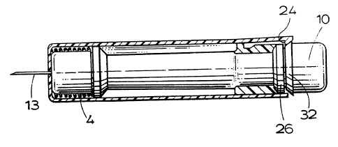
The cover member 3 substantially surrounds the
body 1' and has side walls 20 of larger internal
diameter than the outer diameter of the body 1, a front
end face 21 having a central hole 22, and carries one
or more resilient deflectable fingers 23 at its rear
end. The finger 23 has a latching face 24 and a
chamfered face 25.
The body 1' of the injector assembly 1 has at its
rearward end a radially projecting latching rib 26 and
one or more guide fins 27,28 extending radially
outwards adjacent the rib 26. At least one of the
fins, fin 28, has a recess 29 axially spaced from the
rib 26 and defines forward and rear abutment faces 30
and 31. The rearward end cap 10 has a chamfered end
face 32. ThE~ forward end of the body is provided with
WO 93/13819 PCT/GB93/00006
to
an abutment rib 33 adjacent the end cap 17. The
spring 4 surrounds the end cap 17 and abuts against the
rib 33, continually urging the end face 21 of the cover
member 3 away from the body 1.
In the pre-injection condition shown in Figure 1
the finger 23 is latched onto the rib 26 and the cover
member 3 is held in place against the end cap 17, with
the spring 4 compressed.
When the user wishes to use the injector he
places the end face 21 against his leg (or other body
part, or against the body of someone else to be
injected), then removes the safety pin 9 and presses
the end cap 10. The face 32 engages the face 25. and
biases the finger 23 radially outwards, releasing the
finger from its engagement with the rib 26.
Simultaneously the spring 5 is released and the
needle 13 is driven through the hole 22 and into the
user. The hole 22 may be covered by a membrane for
hygiene purposes.
Since the end face 32 of the cap 10 is now
adjacent the rib 26, as shown in Figure 2, when the
user moves the injector away from his leg the head of
the finger 23 cannot return to its radially inward
position of Figure 1 (there is not a big enough gap
between the rib 26 and the end cap 10) and the spring 4
moves the cover member forward to its advanced position
shown in Figure 3 in which the needle 13 is held in a
chamber 34 defined by the cover member. The head of
the finger 23 is received in recess 29 and the face 24
of the finger 23 is engaged against face 30 and this
restrains further forward movement of the cover member.
WO 93/13819 ~ ~ ~ ~ PCT/GB93/00006
11
In the embodiment of Figures 1 to 4 the cover
member 3 is advanced automatically, but it may possibly
be moved manually back against the action of spring 4
because of t:he possibility of co-operation between the
sloping faces 24 and 31.
In a modification the face 31 is not sloped,
instead it forms an abutment preventing the return of
the finger in an axial direction. For example the flat
end face of the finger, referenced as 25' in Figure 4,
may abut a complementary radial face. Thus the sharps
system is locked in its needle-covering position.
Figures 5 to 7 show another automatic injector 51
incorporating an automatic sharps system. The
injector 51 ~~omprises an injector assembly 52 which is
similar to the assembly 2 of Figure 4, (and similar
components have been given the same reference numerals)
and a genera:Lly cylindrical cover member 53. The cover
member 53 has a forward portion 54, an internal annular
abutment ridge 55, and a rearward portion 56.
The forward portion 54 has a front end wall 57
provided with a central hole 58 and in the
pre-injection: condition shown in Figure 5 defines a
space 59 between the forward end cap 17 of the
assembly 52 and the front end wall 57. A spring 60
engages the wall 57 and the abutment rib 33 of the
injector assembly 52 and continually urges the wall 57
away from the rib 33.
The rearward portion 56 of the cover member 53 has
a pair of radial arms 61 extending away from it at its
rearmost end, which is open. The injector assembly 52
is received i.n the cover member 5:3 and is substantially
WO 93/13819 PCT/GB93/00006
12
surrounded by it, the end cap 17 of the injector
assembly 52 being held in the space 59 by the ridge 55.
To use the injector 5i the user places the front
wall 57 of the member 53 against his, or someone
else's, body part, removes the safety pin 9, places his
index finger 62 and middle finger 63 in front of the
arms 61, and his thumb 64 on the rear end cap 10, and
then presses the end cap 10 with his thumb, in the
manner of operating a manual hypodermic syringe.
The initial phase of pressing of the cap 10
compresses the spring 60 until the front end cap 17
engages the wall 57. The second phase of pressing the
end cap 10 releases the detent teeth 7 and spring 5 of
the injector assembly 52, thereby firing the needle 13
into the user's body and injecting the contents of the
injector. The strength of the spring 60 and the force
necessary to release the detents 7 are arranged
appropriately for the spring 60 to be compressed before
the spring 5 is released.
When the user removes the injector for disposal
the spring 60 moves the cover member 53 over the needle
and surrounds the needle with the rigid forward
portion 54.
Figures 8 to 10 show a modified injector 81 having
an injector assembly 82 and a cover member 83 attached
to the end of a body 1' of the assembly 82. The
assembly 82 is very similar to that of Figures I to 4
and the same reference numerals have been given to
similar components.
The body 1' of the assembly 82 has an external
flange 84 which co-operates with a tear-off strip 85 of
CA 02127359 2005-04-04
13
the cover member 83. The cover member 83 can be
considered to be similar to end cap 17 of the
arrangement of Figure 4, except that it is biased by a
spring 86 away from the bush lfi. The spring 8fi engages
the end of the body 1° and the inside of the end wall
of the cover member 83.
The injector 81 ~.s used in the same way as
described in WO 92/12745, except that after injection
the user tears off strip 85 which releases the
spring 86 and causes the cover member 83 to move
forward and enclose the projected needle. The cover
member 83 and body 1° have complementary lugs 87 and 88
which prevent relative longitudinal movement beyond the
position shown in Figure 10.
Alternatively the strip 85 could be torn off
before use, which would give an injector similar to the
injector lIl illustrated in Figures 11 to 13. The
injector 111 has a spring 112 and a cover member 113.
Injector 111 can be arranged to operate in a
similar manner to injector 5I in that ita spring 112 is
compressed by the action of pressing on its rear end
cap, actuation of the injector occurring after the
injector assembly has moved towards the cover member.
Alternatively, the user may push the cover member 113
of the injector 111 against his person by holding the
sides of the body 1' and then actuate the injector.
This could, of course, also apply to the injector 5l.
Figures 14 to 16 show an injector 141 having an
injector assembly 142. and a cover cap or member 143.
The injector assembly is largely as shown in our_.~
published European Patent Application No.O 361 fi68..
WO 93/13819 PCT/GB93/00006
14
The assembly 142 comprises many components similar
to those of assembly 2 and similar components have been
given the same reference numerals.
The body 1' of the injector assembly 142 has
towards its forward end an abutment flange 144. The
rear end cap, referenced as 10', is longitudinally
elongated and extends from the rear end of the body 1'
to just before the flange 144 (in the pre-injection
position shown in Figure 14). A spring 145 bears
against an end wall 146 of the cover member 143, and
against the bush 16, and continually biases the cover
member 143 away from the body 1' so as to define an
enclosure 147. The cover member 143 has an annular
projection 148 at its rear end which co-operates with a
complementary projection 149 on the end of the body 1'
to retain the member 143 to the body.
The user places the wall 146 against the area to
be injected, removes the safety pin 9 and presses on
the rearmost end of the end cap 10'. The spring 145 is
compressed until the end of the cylindrical side csalls
of the cover member 143 engage the flange 144
whereafter force is transferred back to the detents 7.
Further pushing on the end cap 10' causes the detents 7
to be released, the needle to be injected into the
recipient, and the contents of the injector 141 to be
injected. After removal of the injector from the
user's body the spring 145 moves the cover member 143
over the needle to hide it.
Any or all of the injectors described could have a
locking arrangement for their cover members such that
once the cover member moves so as to hide the needle
after injection it can be manually, or automatically,
WO 93/13819 ~ ~ ~ ~ PCT/GB93/00006
locked against retraction such as would expose the
needle again.
A locking condition of the cover member may be
achieved in substantially the post-injection positions
shown in the drawings, or there may be further relative
movement between the cover member and the body to a
locked position.
One possible automatic locking mechanism is shown
in Figures li to 19. For the sake of convenience the
arrangement will be described with reference to the
embodiment of Figures 14 to 16, but the structure is. of
course applicable to any of the injectors.
The cover member 143 has means, bayonet means 150,
which co-operates with means, track or groove
means 151, provided at the end region of the body 1'
such as to provide a one-way path to a locking position
as the cover member 143 is moved towards the body 1'
and then released away from it again.
The bayonet means 150 comprises a stud 152
projecting radially inwards from the ring of the
annular projection 148. The cover member 143 has a
longitudinal slot provided in it adjacent the stud 152
so as to enable the side wall of the member 143 which
carries the stud 152 to flex radially outwards, as will
be described.
The track means 151 comprises a portion 153
extending rearwards, and a portion 154 extending back
forwards. A locking hole 1.55 is provided at the
forward end of the portion 154. The locking hole 155
has a step 156. The rearwardly extending portion 154
of the track 151 has a sloping base which is deeper at
WO 93/13819 PCT/GB93/00006
16
its forward end, and reaches its shallowest point
(referenced as 157) before its rearmost point, and then
becomes deeper again. This is the portion A to B shown
in Figures 17 and 18.
The forwardly extending portion 154 of the
track 151 has a base which slopes from a shallow end
(point B) spaced from the forward end of the body 1' to
a deeper end (point D) adjacent the forward end of the
body. The locking hole 155 is at the deeper end of the
forwardly extending portion 154. The rearwardly
extending portion 153 is curved and bends to meet the
forwardly extending portion 154. Of course, the
track 151 could have regions where its base is flat.
In use, as the cover member 143 is moved towards
the body 1' the stud 152 rides up the slope of the
rearwardly extending portion 153 of the track until it
reaches point 157, the side wall of the cover member
flexing radially outwards, and then rides down the
slope beyond point 157 and around the bend in the
rearwardly extending path 153. As the cover member
moves forwards relative to the body 1' the stud 152 has
a tendency to move "downhill", which guides it to move
along the portion 154 of the path, rather than
returning along portion 153. The stud 152 snaps into
hole 155 and the step 156 prevents the cover member
from being pushed back again relative to the body 1'.
It will be appreciated that in the embodiments of
Figures 1 to 4, and 8 to 10, where the cover member
does not move towards the body before being advanced,
there is no need for such a complicated one-way track.
The locking means could simply comprise the forward
portion of the track.
WO 93/13819 PCT/GB93/00006
a
17
Of course, the stud could be on the body and the
track in the cover member. There may be more than one
stud and as:~ociated track. The forwardly extending
portion of the track may be curved, either in addition
to or instead of the rearwardly extending portion (when
provided)
Figures 20 to 22 show another modification which
is applicable to any of the injectors described.
Figure 20 shows an automatic injector 160 before use.
The injector 160 has a body 161, a needle 162, a needle
guide 163 having a needle hole (or thin-walled
region) 164, a cover member 165, and a spring 166. The
front end of the body 161 has a flange or shoulder 167
which is inclined relative to a plane normal to the
needle 162. 'rhe cover member 165 has a front wall 168
having a through-hole (or a thin walled region) 169
through which the needle 162 extends in use, and a
rearward flange 170 which co-operates with a flange 167
of the body.. There may be a membrane (which may be
similar to seal 15 of the arrangement of Figure 4)
provided at t:he forward end of the injector, the needle
piercing the membrane during injection.
The spring 166 urges the front wall 168 away from
the body 161,, with the flange 170 engaging against the
rearmost portion of the flange 167. Since the
flange 167 i;s angled relative to the body (it is not
perpendicular to it) the cover member 165 is urged by
the spring 166 to a cocked position, shown in
Figure 20, until the flanges 170 and 167 engage at both
sides of they body (at the top and bottom as seen in
Figures 20 to 22). The hole 169 is mis-aligned with the
hole 164 .
WO 93/13819 PCT/GB93/00006
18
~dhen the user presses the wall 168 against his leg
the cover member 165 is moved towards the body 161 and
the cover member and body take up a concentric
configuration, with the holes 164 and 169 aligned as
shown in Figure 21.
t~;hen the automatic injector operates the needle
passes through the holes 164 and 169 into the user's
body (and through any sealing membrane which may be
provided).
PJhen the user removes the used injector from his
body part that has just been injected the spring 166
pushes the cover member 165 to its advanced position.
As the cover member slides forwards the needle 162,
which is projecting from the body, keeps it concentric
with the body until the wall 168 moves beyond the
forwardmost tip of the needle whereafter the spring 166
again causes the cover member to take up its cocked
configuration because of the inclined flange 167.
Accidentally pushing on the front wall 168 of the cover
member now causes the wall 168 to engage the needle and
this stops the cover member from being moved further
towards the body and ensures that the needle is safely
covered. Accidental re-location of the needle 162 in
the hole 169 is very unlikely and the mis-alignment of
the needle and hole 169 effectively serves as a lock
for the cover member.
Of course, the flange 170 could be inclined so as
to serve as mis-alignment means, either in addition to,
or instead of, the inclining of flange 167.
The forward end portion of a modified injector 180
is shown in Figure 23. The injector 180 has two
modifications of note, the first of which is that
WO 93/13819 ~ '~ ~'~~ ~ ~ PCT/GB93/00006
19
instead of having an end cap with a small needle
aperture to define a sharps enclosure for the needle,
it has an opE~n-ended sheath, sleeve, or tube, 181. This
may be easier or cheaper to manufacture. The protective
sheath 181 rnay need to project further than an
equivalent end cap with a substantially closed end in
order to protect the needle properly. It may even be
acceptable to allow a user deliberately to insert his
finger into the open end of the sheath and reach the
needle, so long as it is unlikely to occur
accidentally. On the other hand the sheath 181 may be
too narrow or too long (in its advanced position) to
allow an adult, and/or a child, to push their finger
inside it and reach the needle after firing of the
injector.
The injector 180 also has a second difference from
those previously described and that is that the rear
end of the :>harps spring 182 (which urges the sheath
forwards) hears against a plastics or metal
load-spreader plate 183 which in turn bears on the
rubber bush 16. This spreads the load of the spring and
avoids the bush 16 deforming locally as it might if the
spring 182 were to contact it directly (and over a
smaller area). The load spreader plate 183 may engage a
radial shoulder on the forward end of the body 1',
thereby transferring force directly to the body,
without stressing the bush 16 significantly.
Alternatively, another way of avoiding applying
excessive load to the rubber bush 16 is to have the
plate 183 integral with the body 1' of the injector.
This is effectively mounting the spring 182 on an end
cap of the injector.
In the arrangement of Figure 23 the spring 182
bears against a circlip 184 received in a groove in the
WO 93/13819 PCT/GB93/00006
inner wall of the sheath 181. The circlip 184 and/or
spring 182 may serve as an obstacle to the user's
finger if the user tries to reach the needle.
It will of course be appreciated that the feature
of an open-ended sheath providing the cover member for
the needle, and the feature of the spring bearing on a
load-spreader plate, or an end cap of the injector, can
apply to any of the embodiments described.
Figure 24 shows an arrangement similar to the
arrangement of Figures 8 to 10, but modified along the
lines mention above. The injector, referenced 190, has
a rigid plastics material end cap 191 similar to that
disclosed in our co-pending patents already referred
to, and a spring 192 urging a sharps cover 193 away
from the end cap 191. The end cap has a centering, or
retaining, ring 194 moulded on its forward face which
serves to locate one end of the spring 192. The end
cap 191 is permanently fixed to the body of the
injector.
Figure 25 shows another injector 200. The
injector has a body 201 formed from an outer tubular
member 202 and an inner tubular member 203. The outer
member 202 is provided with a collar 204 which defines
in part an annular space 205. The inner member 203
also helps to define the space 205. A sharps cover 206
is provided extending over the forward end of the inner
member 203. The cover 206 has sidewalls 207 which are
capable of entering the space 205, and retaining
formations 208 which are trapped in the space 205 by a
shoulder 209 provided on the collar 204. The
collar 204 is in this example provided on the outer
tubular member 202 and the separate inner member 203
which contains a medicament chamber 210. The outer
~.~~'~3~9
WO 93/ 13819 PCT/G B93/00006
21
member 202 has an annular groove 211 which receives
projecting locating formations 212 of the inner
member 203 iii a snap-fit manner. The outer member 202
can move slightly axially relative to the inner
member 203 t« actuate the injector. The injector has
an end cap 2:13 which has a locating formation 214 to
locate a spring 215 which bears against the cover 206.
In use 'the rearward part of the side walls of the
cover slide into the internal space 205. Because the
cover 206 slides in an internal space the space cannot
easily become blocked with dirt or other obstructions.
The arrangement of Figure 25 is front actuated in
that the user must press the front of the injector
against his body for the injector to operate. The
cover 206 must therefore be in its retracted position
for the injector to operate. It is not possible for the
user to actuate the injector without retracting the
cover 206. This avoids any possibility of the user
injecting into the space defined by the cover member
when it is :in its advanced position. Similarly it is
very difficult for a user to actuate the injector of
Figure 24 without compressing the cover member. The
only way he can do it is to grip the body of the
injector just behind the cover member 193. This is
unlikely to occur accidentally. Furthermore, the
injector of Figure 24, and indeed any of the automatic
injectors, can be made front actuated fool-proof
injectors by using the principle of an outer sleeve
extending substantially the full length of the injector
as exemplified in Figure 25.
Figures 26 to 28C illustrate a way of reducing the
axial length of an injector having a sharps system. It
is desirable to have an injector in accordance with the
WO 93/13819 ~ PCT/GB93/00006
~:~~'~~5~
22
invention, but which is not too much longer than a
comparable injector which does not have the sharps
system. The injector, referenced as 220, has a guide
track 221 comparable with track means 151 of the
embodiment of Figures 14 to 16. However, instead of
the track 221 having rearwardly and forwardly extending
portions, 223 and 224 respectively, of equal
longitudinal, axial, length, the forward portion 223
takes the cover member (referenced as 225 in
Figures 28A to 26C) further forwards than it is in its
pre-injection position. The track has a double cam,
with crest 222 being. shown. The cover member can be
considered to be about 80~ retracted towards its
injection position (20% advanced towards its
post-injection position) in its pre-injection position.
There is a snap-fit lock 226 (see Figure 27A)
operable at the post-injection position to prevent the
cover member from being retracted again. The cover
member 225 has a pin, or the like, which is guided in
the track 221, and locking means (usually the guide
pin) which co-operates with the snap-fit lock 226.
There may also be a lock, or releasable latch
means, to hold the cover in its pre-injection condition
against accidental movement therefrom. The
pre-injection latch could comprise a component which is
manually destroyed before the injector is used (such as
a tear-off band), or it could comprise a snap-fit
latch, for example a stud engaged in a complementary
hole.
It will be appreciated that it is preferable to
have the spring which engages the sharps cover member
weaker than that the force necessary to be applied to
the rearward end cap of the injector to actuate it.
WO 93/13819 ~ ~ ~ ~ ~ ~ ~ PCT/GB93/00006
23
This means that when the injector is placed against a
user and its rearward end cap is pressed to actuate the
injector, the injector will fire only after the sharps
cover member has been fully retracted.
The sharps cover member may be manufactured by
moulding it as a cylinder. Alternatively we may find
it better to mould it as two half-cylinders, possibly
joined by a living hinge, and to join the two half
cylinders together around the forward end of the body
of the injector to assemble the sharps cover member,
and simultaneously attach it to the body of the
injector. 'rhe two half-cylindrical portions of the
sharps cover member may have complementary
interengagable snap-fit formations to enable the two
halves to be joined together with a snap-fit operation.
We may also care to mould the sharps spring into
the sharps ~~over member. There may be a plastics
moulding spring.
Another arrangement for a fully automatic sharps
system for an automatic injector comprises having a
resilient compressible member, such as a foam sponge or
the like, mounted at the front end of the injector (for
example bonded to the front end cap, such as cap 17 of
Figure 4). When the injector is unactuated its front
end (i.e. the resilient compressible member) can be
pressed against the user's body prior to release of the
drive means, compressing the axial length of the
resilient compressible member, and thereby bringing the
user's body part within range of the needle when the
injector is actuated. Upon actuation the needle passes
through the resilient compressible member, which may
have a hole to assist this, and into the user's body
part. As the user moves the injector away from his body
WO 93/13819 PCT/GB93/00006
24
after injection the resilient compressible member
expands again to cover the needle. Thus after use the
needle is encased in the resilient compressible member,
giving sharps protection - or at least a degree of
protection. The needle is hidden by the resilient
compressible member and can never be seen.
Instead of having a resilient compressible member
which is compressed in use and then expands, the
injector could be provided with an expandable member
which is in a compressed condition, or a partially
compressed condition, during storage of the injector
(and during an injection) and which is ,released to
expand and cover the needle after injection. The
expandable member preferably expands automatically
after injection to provide an automatic sharps system.
The expandable member may comprise a resilient
material, such as a foam sponge.
The resilient compressible member or expandable
member could be provided as the cover member, or inside
or behind a more rigid cover member (thereby acting as
a spring).
A further modification may be to have the
resiliently compressible member, or expandable member,
comprise a helical spring. The coils of the spring can
take the place of side walls of a rigid cover member,
the released spring surrounding the needle and thereby
comprising a cover member. The spring may have an open
end (akin to the arrangement of Figure 23) or it may
have an end plate with a needle aperture. Even though a
tubular spring surrounding a projecting needle is not
rigid it can still be an effective cover member, for
example the end plate could have its needle aperture
mis-aligned with the needle after injection. The spring
WO 93/13819 PCT/GB93/00006
~1~'~3~9
could have a bent, non-straight, relaxed condition. The
spring could be a conical spring so that the projected
needle cannot be seen between the coils of the expanded
spring, or at least is substantially obscured from view.
The sharps assembly, of whatever kind, may be
released for movement by the action of injecting. For
example it may be released (as in the arrangement of
Figure 26) by the rearward movement of the cover
member. Alternatively the sharps assembly may have
release means actuated by movement of the drive means
or expulsion means.
In yet another embodiment of the invention an
automatic injector may have a cover member
screw-threaded onto the forward end of the body of the
injector. Automatic unscrewing means (such as a
spiral/torque spring) is provided acting between the
cover member and the body. The cover member has a
release feature akin to that of Figures 17 and 26 in
that the cover member is initially in an intermediate
axial position, pressing the cover member against the
user's body moving the cover member back a distance
(say 200 of its eventual forward travel). This rearward
movement of the cover member releases the screw-action
locking mechanism - (it may allow the screw thread on
the cover member to engage the rear portion of the
screw thread on the body, or they may already be
interengaged). After the injector has been fired it is
removed from the skin. The automatic unscrewing means
operates to unscrew the cover member thereby extending
the cover member forwards. The screw threads have a
sufficiently low helix angle that when the cover member
is extended merely pressing it back axially has little
effect: an angular torque is required for ease of
movement. Thi:~ is less likely to happen accidentally.
WO 93/13819 PCT/GB93/00006
~1~'~3~9
The automatic unscrewing means may advance the
cover to such an extent that it is fully unscrewed from
the thread on the body - the screw threads may no
longer co-operate. The cover member is then, of course,
still retained to the body by retaining means to stop
it falling off. Since the screw threads of the cover
member and body do not now mate the cover member cannot
be accidentally pushed back to reveal the needle. Thus
the screw threads provide automatic locl~:ing of the
cover member in a needle-protecting position (even
though the cover member may not be rigidly held to the
body it is still prevented from exposing the needle
accidentally).
Any of the features of any one of the injectors
disclosed may be used in combination with another
injector.
Tear-off bands are considered advantageous because
they can be used to keep an injector in a retracted,
compressed, condition prior to use, and so keep the
part of the injector against which the cover member
slides covered up so that it cannot become clogged up
with dirt or other obstructions. A tear-off band could
be used even when the injector has its cover member in
an advanced, or partially advanced, position when the
injector is in its storage condition simply to ensure
that the area of the injector body that is to have the
cover sliding back over it in use is not liable to
become blocked. The tear-off band could be removed
immediately prior to using the injector. Preferably
removal of the band enable the injector to be
actuated. A tear-off band, or some other lock, is very
useful on automatic injectors which have sharps systems
which lock in place when fully advanced in order to
prevent accidental movement of the sharps cover to the
WO 93/13819 ~ ~ ~ ~ ~ PCT/GB93/00006
27
advanced pos:~tion before the injector is used (thereby
locking the cover in its advanced position and making
the unactuats~d injector unusable).
A particular advantage of an automatic injector
which has an automatic sharps system is that the needle
is never seen by the user. The only time that the
needle protrudes from the injector is when it is in the
user's body. As discussed, this improves the safety of
the system. A further advantage is the very fact that
the needle is not seen by the user. Some people are
afraid of needles and it can be comforting not to have
to see them.. This can allow some people to use
injectors who would otherwise be psychologically unable
to use them.
One of the areas where we see our automatic
injectors having an automatic sharps system being used
is to combat male impotence. A man can simply place an
automatic injector at the base of his penis and inject
himself without needing any particular skill and he
need never see l~he needle. This can readily be
appreciated as bep~ng an advantage for this particular
use, given t:he natural fear of placing exposed sharp
objects near the genitals.
The invention can also be used with automatic
injector systems which have a pre-filled syringe which
is loaded .into a re-usable or single use firing
mechanism.